SB221 Tank Circuit Voltage Distribution Vs. Frequency
One theory, offered by a California radio amateur, is the tube is a source of unwanted VHF energy caused by parasitic oscillations. Lacking documented tests with reliable equipment, we are shown pictures of damaged components and told to simply "take his word" that the arc damage was caused by sudden bursts of VHF energy. These sudden bursts of parasitic energy, that cannot be replicated, are blamed for arcs in, and damage to, bandswitch, tuning capacitors, and other tank components. No one ever can catch the amplifier in such a state of oscillation, so we are just left with conjecture and speculation that the arc was caused by a VHF parasitic that appears for an instant and then vanishes for weeks, months, or years.
It is very easy to prove if VHF oscillations or oscillations (or normal operation) on any frequency can create an arc. We can test for stability, or we can excite the anode of the PA tube with a known RF voltage level over a very wide frequency range and measure voltage distribution throughout the system with a very high impedance detector probe. The voltage distribution would tell us the frequencies and circuit locations where the highest voltages would appear if the tube "oscillated".
While every amplifier manufactured is claimed to suffer from parasitics, it is impossible to test every PA made. In lieu of that, I picked a PA that is commonly rumored or alleged to have parasitics. The purpose of the series of measurements below is to determine if it is possible for resonances in the tank to INCREASE anode voltage to the point where an arc will occur, or if it just an imagined problem, or a problem "invented" to sell a specific cure that only one source sells.
Regardless of opinions or motives, or our personal feelings about specific theories, looking at the data tells how what happens, voltage-wise, through the tank system path.
Test Method
By injecting the anode with a known voltage, and sweeping the tank slowly over a wide frequency range, we can determine voltage distribution at any point in the tank system. By looking at the relationship of the various test points to anode voltage, we can determine if it is possible to cause an arc at frequencies at any particular frequency.
While it would be nice to drive the input and look at results, it applying RF drive over frequencies between 1 and 300MHz to an HF PA's normal input is not practical or useful. Input circuits and other components normally prevent VHF RF from reaching the tube. In order to document voltage distribution in the tank, we must excite the tank another way. The best method is to inject a constant voltage RF source at the tube anode, and measure voltage throughout the tank without disturbing the distributed impedances. This can be accomplished with a high input impedance detector probe and a constant voltage source that sweeps frequency.
The goal is to replicate actual operating conditions and look for voltage "hot spots". To maintain accuracy, the tank must be adjusted normally. This was accomplished by loading the PA normally with a 100 watt exciter into a 50 ohm dummy load. After tuning and without disturbing tank settings, the amplifier is disconnected from power mains and from the exciter.
Of course an increase in voltage at a specific point wouldn't prove an arc will occur, it simply proves at what point and at what frequency an arc could occur. The higher the voltage at a given swept frequency, the more possible it is for an arc to occur at that frequency. If the voltage is much lower than the injection voltage, at any particular point, an arc at that frequency would be nearly impossible.
The Measurements
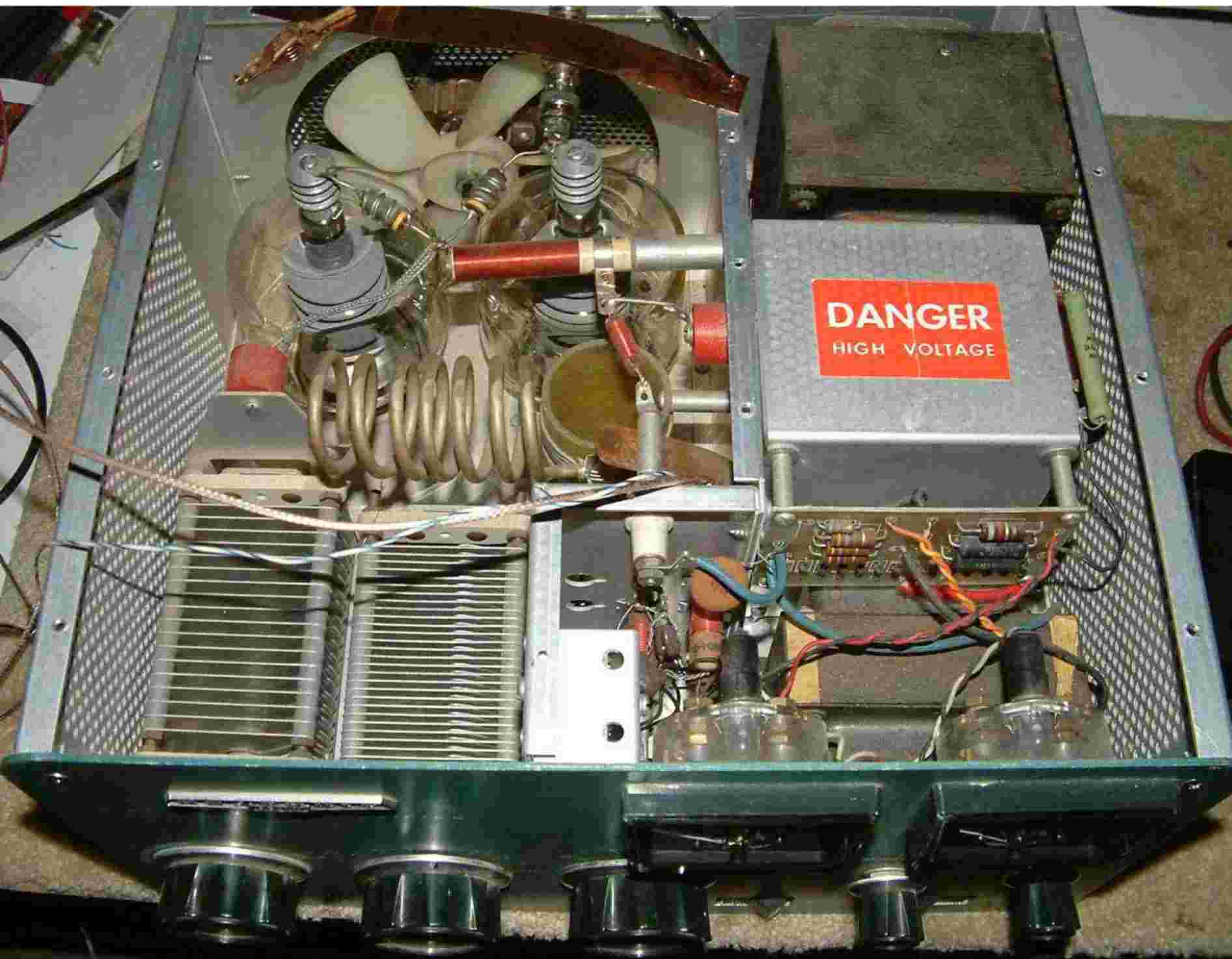
The anode is excited with a swept power-leveled source feeding a bridging pad and the anode. The sweep is from 1 MHz to 300 MHz. The small coaxial cable and multicolored wire are from the high impedance J-FET source follower probe used to feed the second RF port of an Agilent network analyzer. In this condition the network analyzer acts like a sweep generator with a voltage detector.
- HP Network Analyzer source connected to tune anode at tube. Constant power source leveled at 10dBm at injection point load.
- 100k-ohm 3pF active voltage detector probe
- Transmission loss calibrated at zero dBm for mid-scale into the 100k probe as detector, across 2700-ohm resistor.
- All displays 10dB/div voltage, sweep is 1MHz to 300MHz.
- 1600 data points, 5 second sweep time.
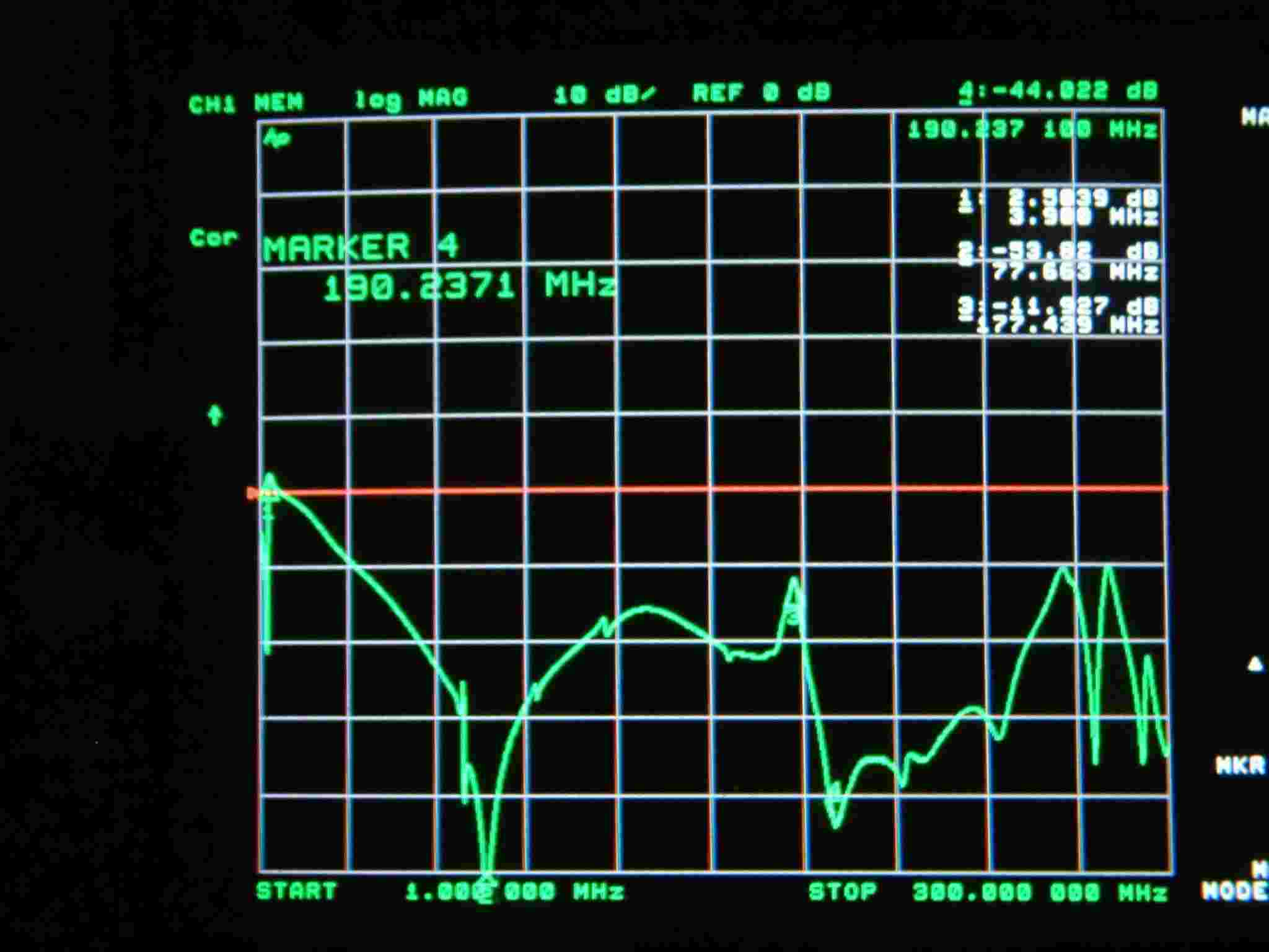
Figure 1. Tank adjusted for normal operation at 3.8MHz. The above sweep is voltage across the tuning capacitor, which is +2.5dB at plate tune capacitor. +2.5dB becomes the reference level for comparing HF voltages throughout the tank system. With the anode at 3000 volts peak swing at 1300 watts on 80 meters, the reference level would be 2.5dB. A 1300-watt parasitic or spurious would develop the same starting voltage swing. That voltage would be attenuated or increased, by the same change as the display indicates, as it "travels along" through through the tank.
In this case at the tuning capacitor, a 180MHz parasitic would be 14.4dB down in level (marker 3) compared to the HF voltage (marker 1). This is 19% of the HF voltage level, or 570 volts peak with 3000 volts of anode voltage swing. A VHF arc at 180MHz would be impossible, unless the anode was swinging 18,000 volts. As a matter of fact, there isn't any frequency very far from the operating frequency where an arc could occur!
A grid dip meter would show a strong dip at 180MHz, because it would be loaded by the tank. This is why a grid dip meter can not locate a "problem frequency", it might actually be locating a good frequency!
Figure 2. 80m position. The above graph indicates voltage at the 15 meter tap to closest arc point on switch. Highest voltage at frequency marker 3 is -12dB at 177 MHz. This is -14.5dB anode voltage, or 19% of anode voltage! 19% of 3000 would be only 570 volts, making it impossible to arc the 15M tap at VHF frequencies. After all, that tap survives constant exposure to over 3000v at the fundamental frequency when operating 80 meters!
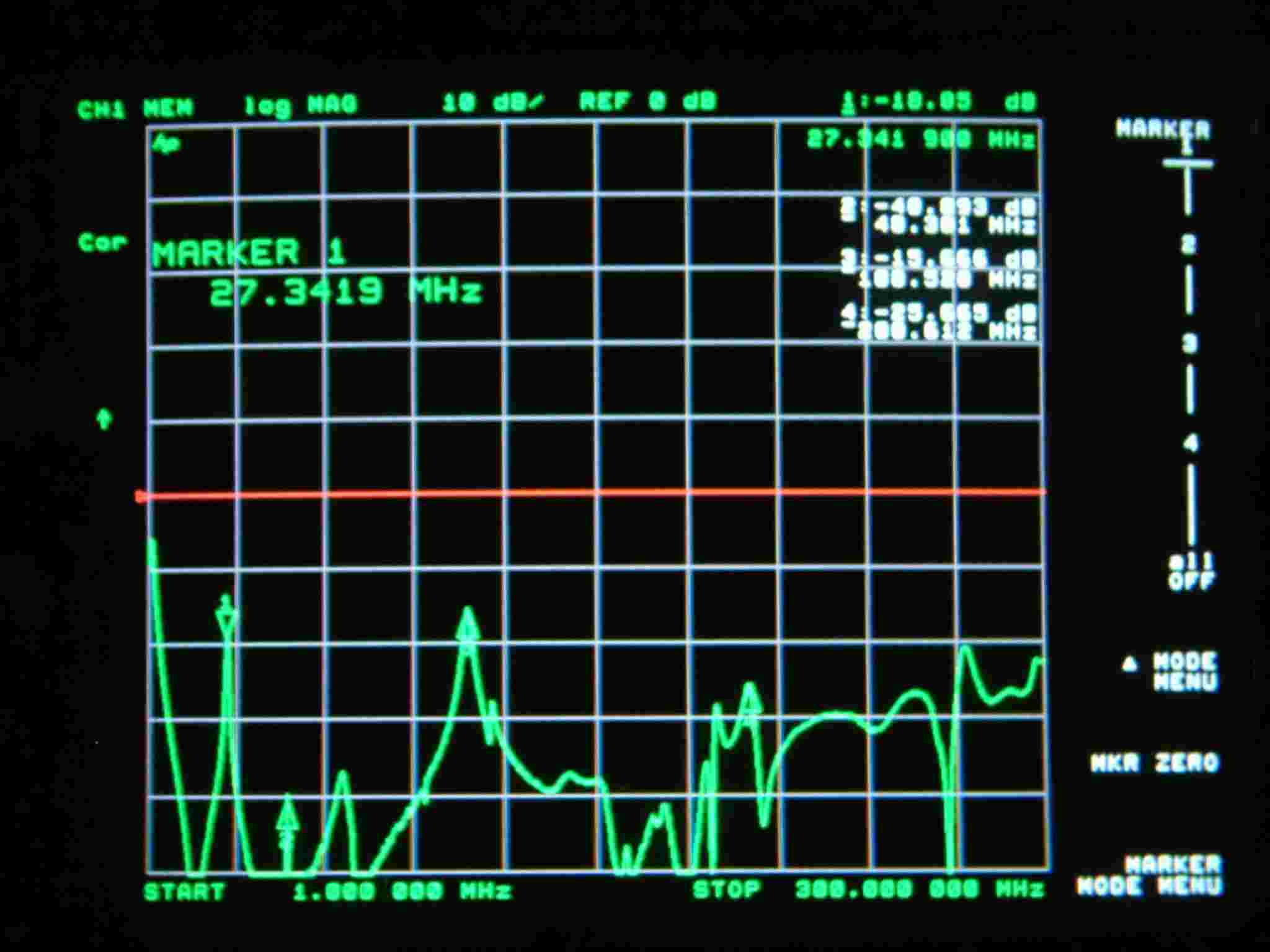
Figure 3. 80m position. Voltage across loading capacitor. All spurious response voltages are at least 20dB down from the anode voltage. No VHF arcs possible here either.
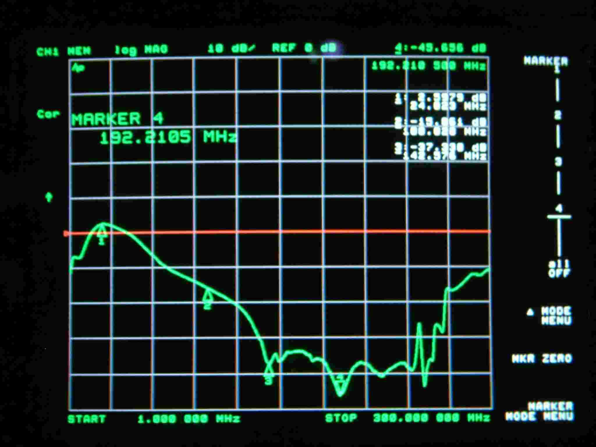
Figure 4. Tank normally loaded on 15-meters. Voltage across tuning capacitor. Anode injection voltage reference at +2.6 dB.
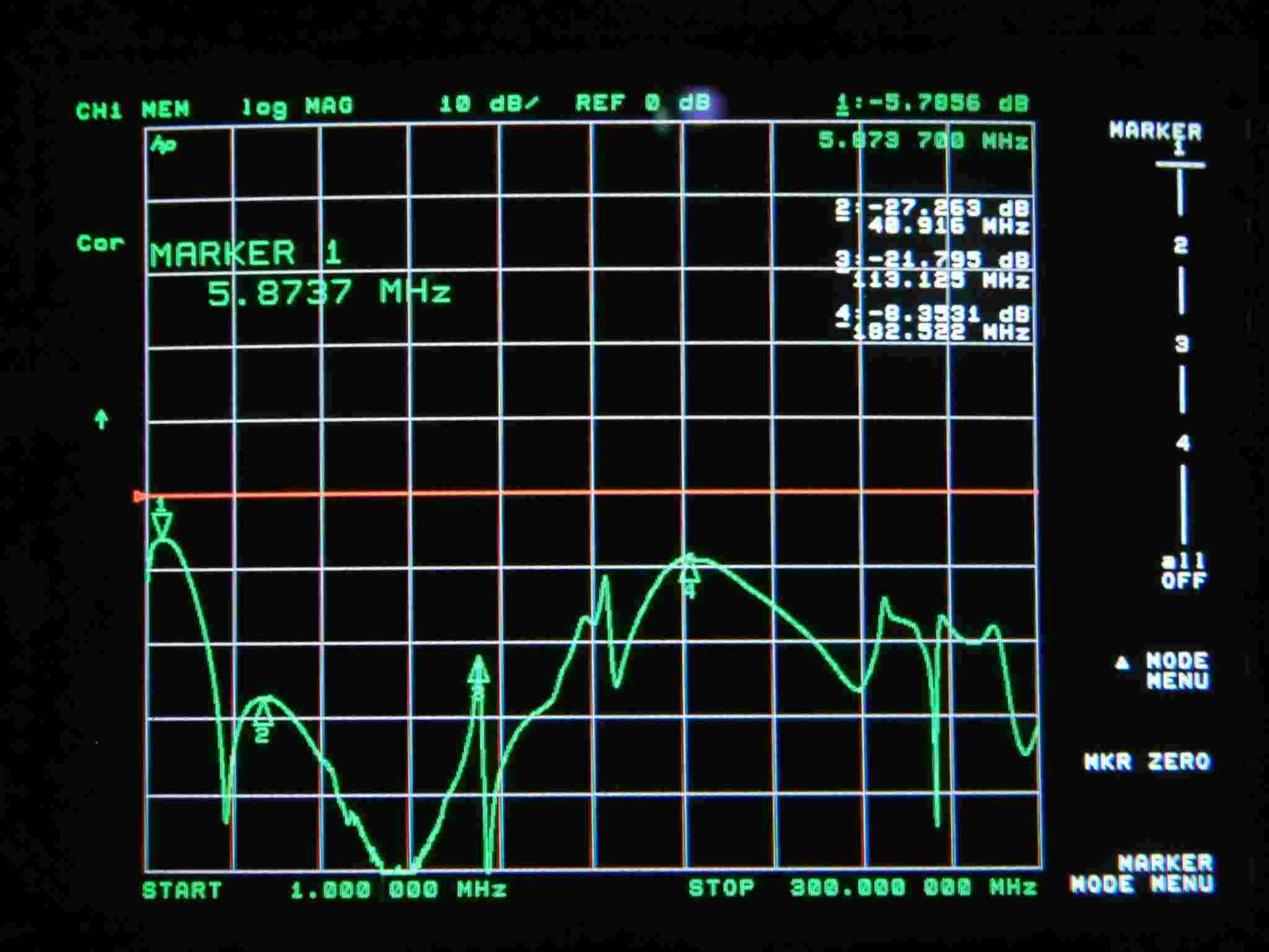
Figure 5. 15m operation. Voltage at highest VHF voltage point in system past the parasitic suppressors. This voltage was at plate blocking capacitor on plate choke side. Point 4 is 11 dB down, or 27% of anode voltage.
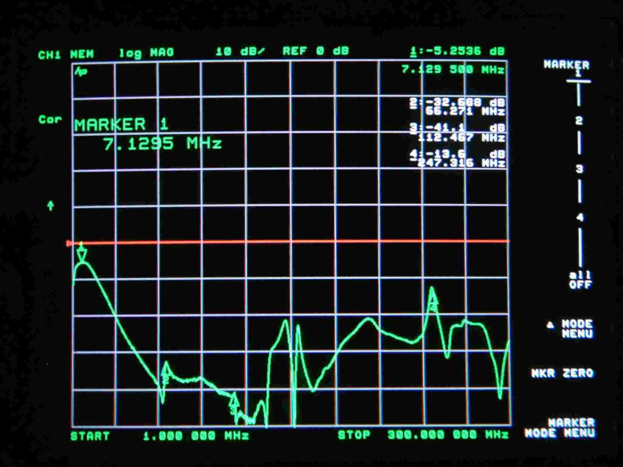
Figure 6. Voltage across loading capacitor at tank-end stud to chassis. Peak at 247MHz is -16dB, or 16% of anode voltage (480v at this point with 3000v at anode). This peak is caused by layout, and the loading cap coupling directly to tubes through stray capacitance from anode system. Impossible to have a VHF arc here, but it could aggravate TVI at USA channel 13.
Conclusion
From the above swept data, we can see VHF voltage would always be much less than HF voltage. The only likely candidate for arcing is improper operation at or near the operating frequency.
What causes arcs? Click here.
More SB221 will be added at a later date. Including performance improvement modifications.