Never loosen the rear set screw on the AL811 series amplifier.
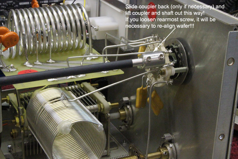
If the rear set screw on the rounded part of the shaft is misaligned, it can be reset with the following procedure:
The input switch in the AL811 is aligned by getting the shaft coupler in the proper position on the setting the set screw on the rear of the ceramic bandswitch section. The goal is to align and center the input switch contacts, as shown below:
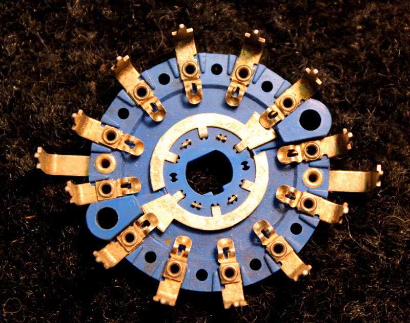
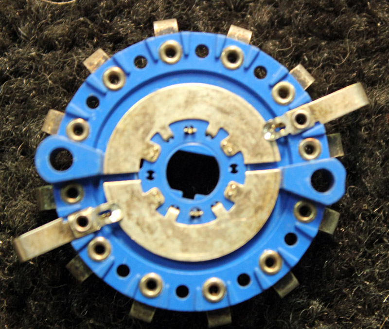
The rotating tabs should be close to center, or some bands will not work properly. This is the 160 meter position viewed from the circuit board side. From this view the switch rotates CCW (counter-clockwise).
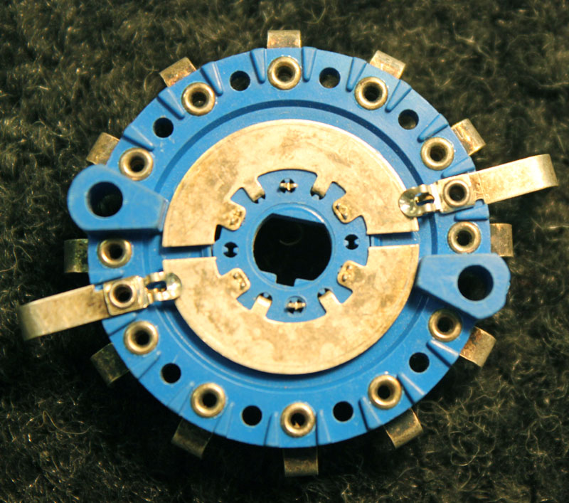
Normal view of wafer 160 position:
Starting at the right side common contact, and going around CCW, we have the following contact order:
right common, 160, 80, 40, 20, 15, 10, left common, 160, 80, 40, 20, 15, and 10.
Note the wafer common commutator is set at about 1/2 of a contact width from the wiper. The commutator gap is set almost in alignment with the two eyelets of the ten meter contacts.
The easiest and safest way to align the switch is to align the gaps with the ten meter contacts while setting the band switch on 160 meters. The pattern is a repeating pattern, so the square keyway on the shaft double "D" hole can be either up or down.
The following are 160 meter error limit examples. This is where operation might become marginal:
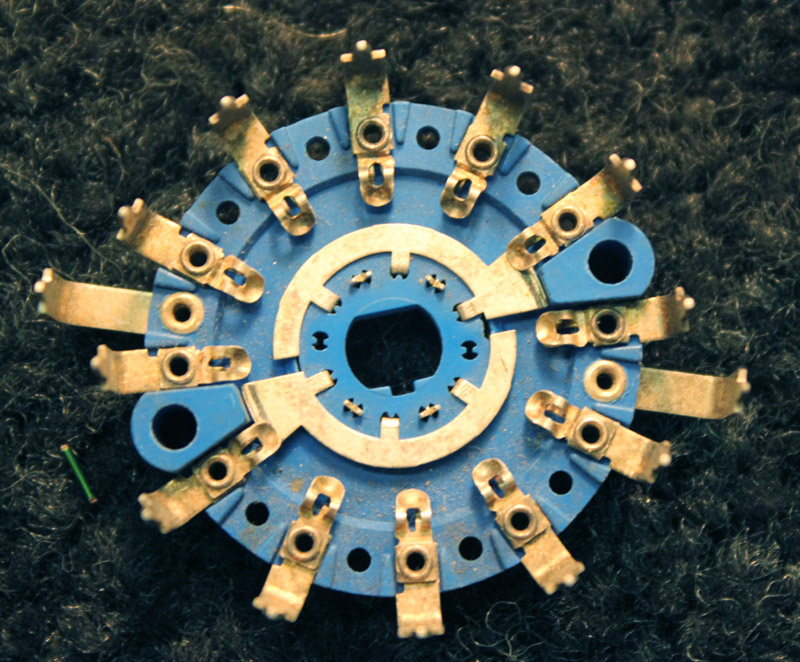
The error limit is where slot alignment hits the edges of the raised areas, or the edge of the common contacts.
Note there is significant tolerance!!
View of switch on board, 160-meter position, proper alignment:
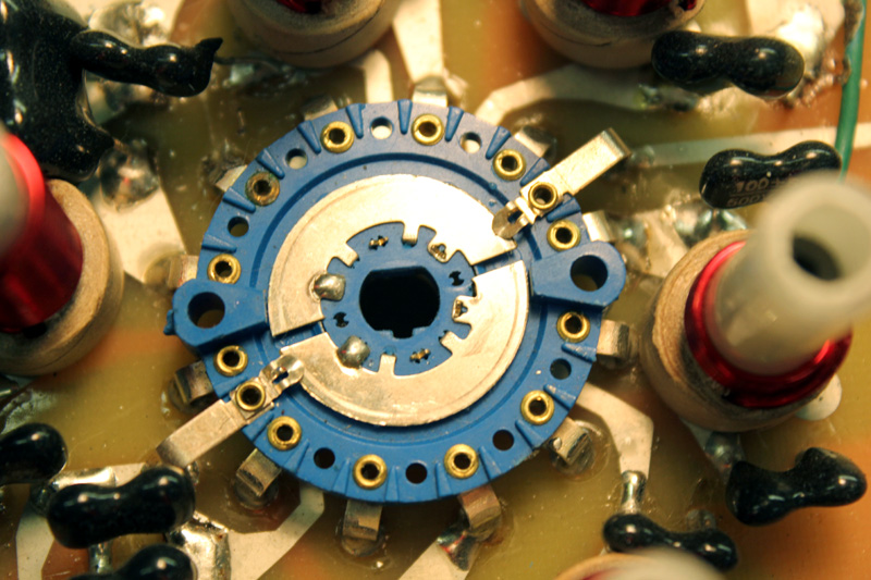
Note while in the 160 meter position, the commutator gaps align with the ten meter contact eyelets.
This means as the switch rotates to higher bands, the gap progresses CW (clockwise) and aligns with 15, 20, 40, and 80, and 160.
| Band position | Gap contact position |
| 160 | 10 |
| 80 | 15 |
| 40 | 20 |
| 20 | 40 |
| 15 | 80 |
| 10 | 160 |
© W8JI 2012