An alternator converts mechanical energy to electrical energy. Understanding how the alternator converts mechanical energy to electrical energy is critical to properly troubleshooting or modifying an alternator system.
The typical automotive alternator behaves like a constant voltage source. This means the alternator output post tries to maintain a certain voltage independently of shaft speed or electrical load. The constant voltage characteristic is necessary to force the battery to full charge as rapidly as possible without damaging or unduly stressing the battery. This also ensure electrical components, such as incandescent lights or semiconductors, operate at acceptable voltages.
The key to this ideal behavior is actually the voltage regulator and how the voltage regulator is connected into the system. Of course the alternator has to turn at a normal operating speed, which is set by pulley ratio and engine speed range, but the regulator remains key to stable running voltage as the load changes.
Many people are moving to single wire alternators. Single wire alternators simplify wiring, but are actually less desirable in high performance applications!
A typical alternator, for example, has a small low current control wire. In many cases this control wire does double duty, not only activating the alternator but also running an alternator warning lamp. The Fox Mustang, for example, runs this control wire through the instrument cluster. The "Battery" lamp is in series with this feed. If the alternator is exceeding 13 volts or so output, the control line comes up to almost 12 volts and the lamp extinguishes. If the alternator is low output, the control wire pulls low in voltage and starts to illuminate the warning lamp. This wire can be used to control the alternator with very little control current. It can shut the alternator off with key off, at wide open throttle, during engine stalls, or while cranking.
Horsepower demand from the engine, ignoring modest changes in electrical performance and frictional losses with shaft speed, is dependent on alternator electrical load.
Within limits of normal operating speeds, the electrical load determines the horsepower load, not the shaft speed. If the shaft is slowed too much, the regulator falls out and the voltage drops. While this reduces shaft or belt loading, it only reduces shaft loading at idle!! While running slow enough to reduce horsepower demand, the battery discharges. This means when you rev the engine up, the alternator loads the belts extra hard to charge the battery. Using an under drive pulley set (smaller crank or larger alternator pulley) actually costs horsepower when racing!
The proper way to set alternator speed is to find the maximum safe alternator speed, and set the pulley ratio so the alternator never goes above that speed at maximum RPM. Let's do an example case or two. These are just examples to show the math using completely fictitious numbers:
| Alternator maximum permissible RPM 27,000 Engine maximum RPM 7,000 27000/7000 = 3.86 or larger drive ratio. This desired pulley ratio is alternator maximum allowed speed divided by engine maximum speed. If the crank pulley is 5.5 inches, the alternator pulley has to be 5.5/3.86 = 1.425 inches or larger or it would spin too fast. This is crank pulley size divided by desired ratio to determine alternator pulley size.
|
| Alternator permissible RPM 25500 Engine RPM 5200 25,500 divided by 5200 is 4.9 if the crank is 7 inches then 7/4.9 = 1.43 inches alternator If you wanted to find the crank pulley based on alternator pulley size, just use ratio times alternator pulley = crank size. So 4.9 times 1.43 = 7 inches
|
Pulley ratio is just the ratio of pulley diameters.
If you want to eliminate alternator drag at high speeds, you need to disable the field winding or power to the regulator. Since there is no access to the field winding (armature or rotor in an alternator), a single wire alternator is not a good racing alternator.
How the Alternator Works
This is a basic description.
An alternator has a rotating electromagnet with many poles, and several other stationary outer windings. The center winding, called an armature, field winding, or rotor, is excited through a carbon brush contacting the slip rings.
The mechanical movement of the rotor changes strength and polarity of the magnetic field in the stationary winding used to generate electricity. This causes the stationary windings to produce an alternating current voltage. That voltage is converted to almost pure direct current by large diodes. A stronger magnetic field and faster movement produces more voltage, and also makes more current and power available.
Without regulation, the voltage produced would be proportional to speed and field levels, and inversely proportional to electrical load. As a matter of fact, if you were to disable the regulator or abruptly reduce the electrical load, voltage of a 12 volt alternator can reach hundreds of volts! I've successfully operated 100-150 volt devices directly from a modified 12 volt alternator.
To maintain safe operating voltage, the alternator uses a regulator system.
Regulator
The regulator has an internal precision voltage reference.
The regulator compares that internal voltage reference to the regulator sense terminal. When the sense terminal voltage is lower than the external reference voltage, the regulator supplies current to the alternator rotor. This increases the magnetic field, and that increases the mechanical load on the belts. It also increases alternator voltage and available load power.
When the regulator detects excessive voltage, the regulator removes field current. This reduces load on the belts, and reduces alternator voltage and available electrical load power.
This feedback system renders under drive alternator pulleys useless for reducing engine load. If you slow the armature, the regulator immediately turns up the field power. When field power increases the shaft becomes harder to turn, with the load on the crankshaft eventually returning to exactly the same level as before the under drive pulleys. The exception to this is if the shaft turns so slow the alternator cannot keep up, in which case you will either have to upgrade the alternator or suffer with low battery charge. This change will result in more load at higher RPM, meaning less engine power at high engine speeds as the battery recovers lost charge.
Alternator Upgrade
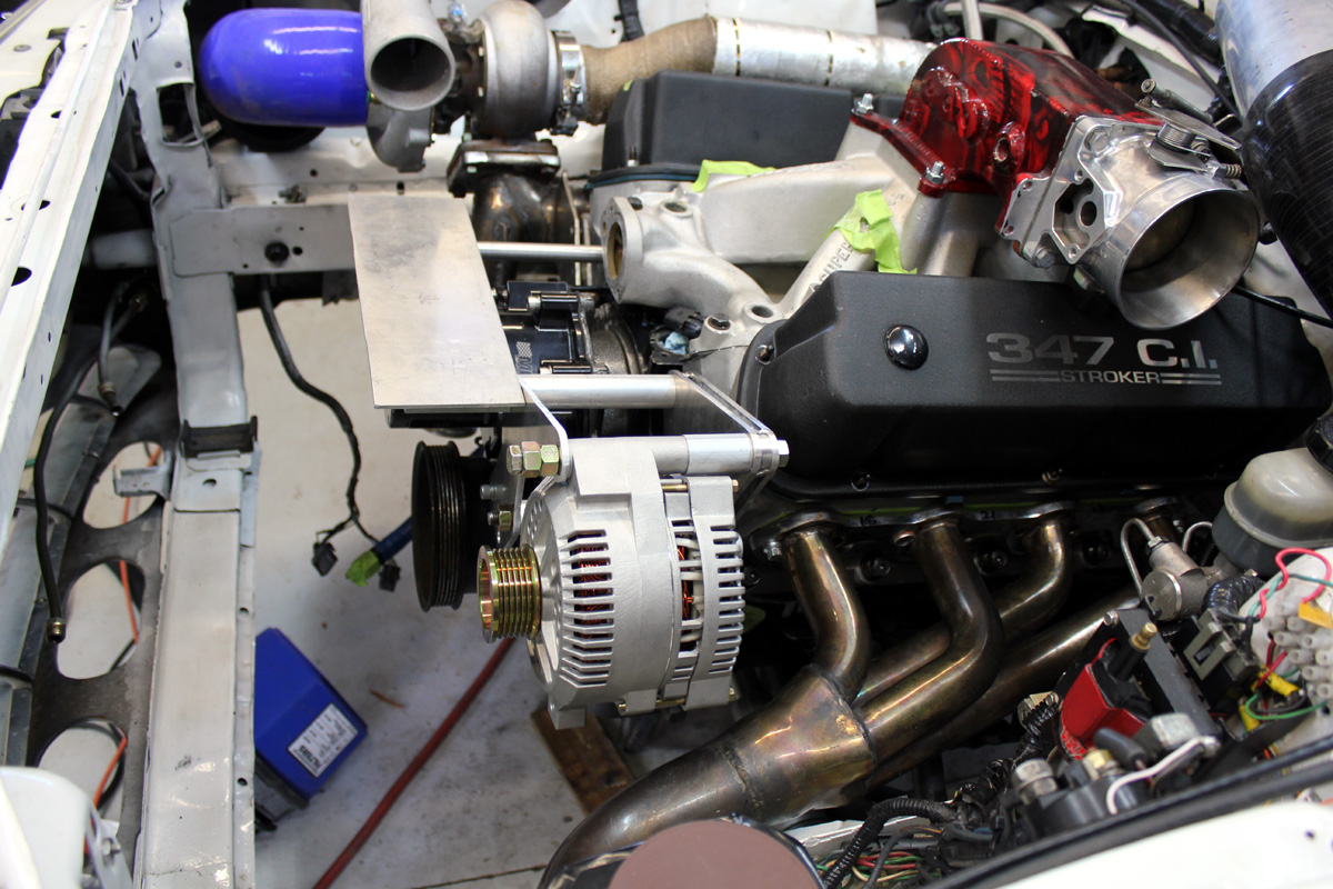
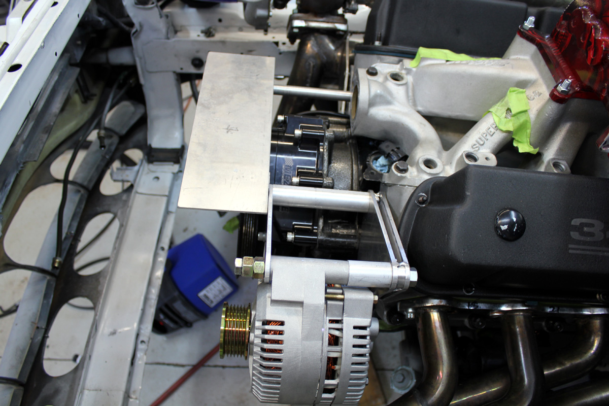
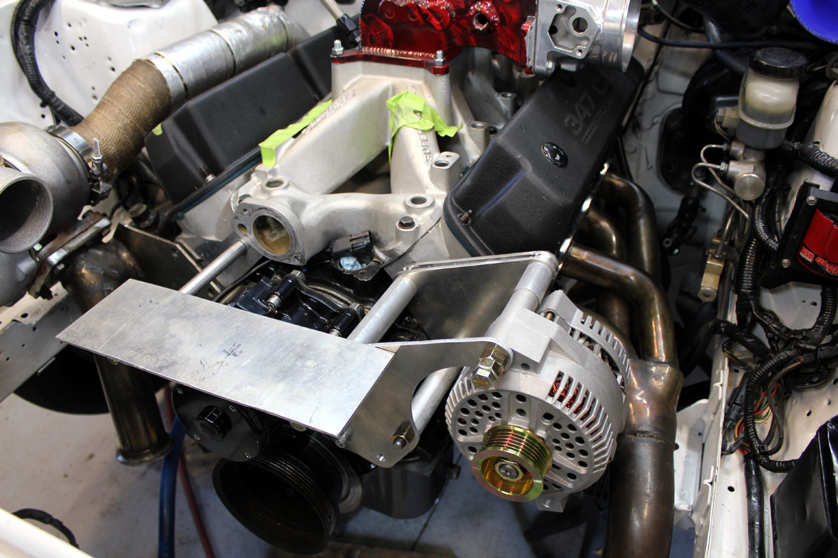
If a car is heavily modified in a way that drastically increases peak current demand, alternator demand can exceed factory alternator limits. Sometime an alternator has to be relocated to allow installation of power adders, like turbochargers or superchargers. I installed an electric fan, electric water pump, and an intercooler pump. Because the car needed to recharge the battery in short run periods, and because demand increased, I upgraded from a 65 ampere to a 130 ampere alternator. I also used the fastest alternator pulley safe for the alternator.
I hand fabricated brackets that offer very rigid support in my alternator relocation: