This page being constructed, while I have time and interest.. last change 2PM EDST Sunday Dec 29, 2013.
Noise and Noise Suppression EMI electromagnetic interference
Mostly, EMI and noise interferes with sensitive computer, audio, and radio equipment. Most of us are familiar with common noise problems, like the musical-sounding tone of alternator whine in speaker systems or the whirring sharp clicks of "spark plug" noise in radios. Those noises follow the speed of the engine.
Noise and EMI causes many problems. What we miss are more subtle things, such as electrical noise causing occasional spark scatter (where timing slightly changes on random ignition pulses) or logging systems or computers lock up.
EMI can also cause false triggering of ignition systems. A falsely induced pickup signal can trigger the sensitive trigger input of electronic ignitions. This is why pickup signal wires are paired, and why they are often shielded. This is why trigger wires should be kept away from injector and plug wires, and the triggering conductor ground wire should be grounded only at the ignition box.
EMI is one cause of cross-coupling between spark plug wires. Although unlikely in practice, this can conceivably cause cross-firing when plug wires are bundled or in parallel. This is why adjacent distributor wires should not be parallel for long distances.
This is not a problem unique to vehicles. Coupling between adjacent wires and ground loops have been problems since the very first telegraph lines, back in the days of wood fired locomotives and stage coaches. This article is mainly concerned with automotive applications.
Noise Sources
A vehicle has several noise sources. They are:
1.) Ignition pulses. In radio or audio systems, this shows as a sharp clicking or ticking that changes pitch directly with engine speed
2.) Injector back-pulse as an active injector is closed. In radio or audio systems, this shows as a clicking or ticking that changes directly with engine speed
3.) Erratic current or sparking in brush-type motors. In radio or audio systems, this shows as a distorted whirring or distorted whining noise that is consistent with electric motor speed. This is common from windshield wipers and fuel pumps
4.) Alternator dc output ripple. In radio or audio systems, this shows as a whine or siren musical tone that varies directly with engine speed. This is aggravated by defective alternator diodes and electrical system ground loops
There are only three ways to suppress noise:
1.) Limit the current and/or voltage that is causing noise
2.) Contain noise in an area where noise isn't a problem
3.) Repair or replace a defective component or device
All noise suppression works by at least one of two things above. Noise cannot be reduced without using at least one of the three correction methods above. We have filtering, isolation, and repair.
Conductors
Conductors offering the lowest impedance for noise and EMI are wide, flat, smooth conductors. This is because of skin effect. Skin effect forces higher frequency currents, or sharp pulses, away from a conductor's center. While wire stranding does not affect direct current, it can have significant effect on higher frequencies. This is because of the air gaps or roughness where most of the current flows, on the outer surface. As a general rule, finer stranding means higher high frequency resistance and impedance. This can be good for suppression if the wire carries noise, like a spark plug wire. This is why they are sometimes a coiled or spiraled thing conductor. It is not good for ground leads, although for most vehicle applications the difference is meaningless.
The important thing is to not let someone tell us finely stranded wire electrically improves ground or power connections. It does not improve the wire electrically. It makes the wire more flexible, which can be important, but it never makes it a better conductor.
If noise or grounding is a concern, the body shell of a unibody car is an excellent ground for every application. The car a car body is very wide and smooth, which makes it a low impedance ground path at all noise and radio frequencies. Even though it is usually steel, the wide surface area and large overall cross-section makes the body almost ideal as a high current dc grounding conductor. This is why computer and radio/audio systems almost always use the car body as the ground reference.
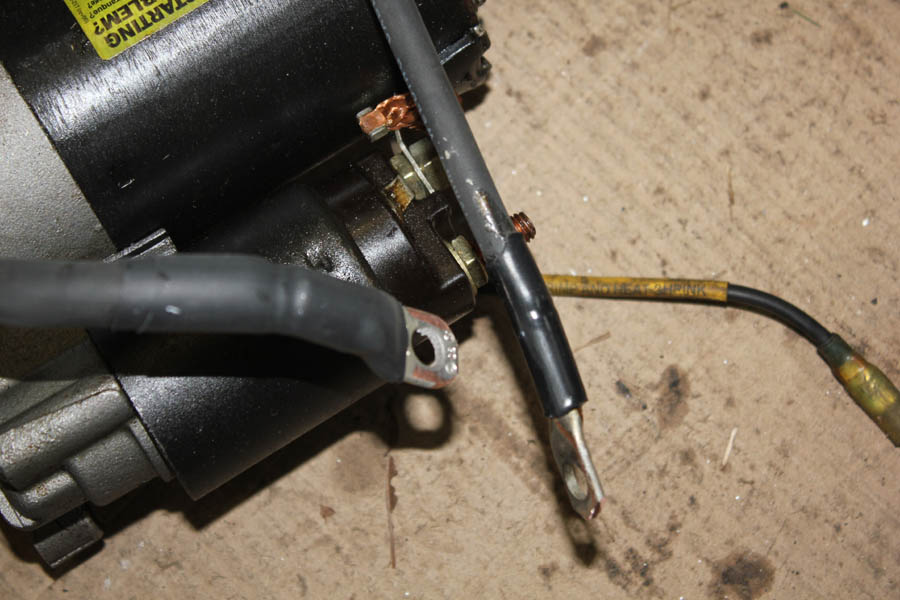
Solid wire is electrically superior for grounding, but is unsuitable in automotive applications. Solid wire, or coarse stranded wire, does not flex nearly as well as finely stranded wire. Solid wire, and even coarse strand wire, will break when constantly flexed or vibrated. This is particularly true if the wire is held rigid out to a concentrated flex point. A broken wire is never good! It most cases it is better to use a short flexible wire to ground, the body shell providing the main ground. By all means use a semi-flexible sleeve to spread flexing or bending load out near any lugs. The heat shrink on the lugs below not only insulates the lugs, it also reduces wire flexing at the lug entrance. Wire flexing tends to slowly weaken the conductors under the insulation until the connection fails.
Ignition Pulses
The ignition system produces a sharp, high-energy, pulse. The ignition pulse repeats at precisely timed intervals to make the proper spark plugs fire at a planned time in relation to each piston's position. In a standard 4-cycle engine, pulse rate is one pulse every other revolution per cylinder.
This is PRR (pulse repetition rate) = rev per time * cylinders / 2
A typical eight-cylinder engine at 1000 RPM has an ignition pulse rate of 1000rpm * 8cyl / 2 = 4,000 pulses per minute (or PPM). The rate is given in minutes because the rotational rate is in revolutions per minute (RPM).
Frequency is normally discussed in seconds (Hz), so we convert the PRR from pulses per minute (PPM) to pulses per second or Hz (formerly cycles per second). 4,000 PPM / 60 = 66.6667 pulses per second per 1000 RPM. This 66.6667 Hz signal, by itself, would be a very low-pitched or low-frequency bass tone if it were a sine wave.
The waveform is not a sine wave. The waveform is a series of very sharp pulses with very fast rise and fall times. The fast rise and fall times have high frequency energy, which makes the pulses sound like clicks or tics. The frequency distribution of the ignition waveform consists of the slow pulse rate modulated with high frequency energy created by the rapid rise and fall. There is a discussion on this website about a radio phenomena called "key clicks", which are very similar to ignition pulses.
Ignition suppression wires reduce radio frequency interference (RFI) through three effects. RFI suppression wires primarily suppress by:
1.) slowing rise and fall times by adding series impedance. This rolls off high frequencies. Rolling off high frequencies rounds the waveform
2.) reducing peak currents by adding impedance. This reduces the magnetic field along the current path, and also reduces spark energy
3.) reducing plug voltages. This reduces the electric field at increasing distances along the plug wire out toward the plug end of the wire
By softening the arc, noise is suppressed. This may seem like a bad idea, but almost all ignition systems have far more spark energy than necessary. This is why resistance spark plugs and resistance wires do not change a car's performance. If spark voltage and current were directly related to engine power, no one would be using resistance plugs or resistance plug wires. Racers have been brainwashed into thinking modest ignition voltage or plug gap changes directly affect engine power. The only cases where more voltage or current improves power are when one or more plugs are on the edge of being able to ignite the mixture, or when a plug is already misfiring from inadequate spark.
Another overlooked issue is current on the ignition coil's ground side. All current at the spark plug wire must be equaled by current on the ground return to the ignition coil. A good ground return from the heads and block to the ignition coil will help keep ignition pulse currents confined to a small area, or contained in a path away from computers and other noise sensitive systems. This the main reason why the factory cylinder-head-to-firewall ground braid is there, and why we should be sure the coil is mounted to a good ground.
Ignition Triggers
Ignition and crank triggers operate at low voltages. The trigger detector system always looks for a sudden voltage transition or reversal. This abrupt voltage change locates the crankshaft position as precisely as possible.
Calculating the time window in seconds for crankshaft degrees, we get an idea how critical the pulse shape and purity is. Let's assume we can tolerate 2 degrees of timing error, and the engine rotates at 5000 RPM. This is 5000/60 = 83.3333 revolutions per second, or 83.3333 * 360 = 30,000 degrees of crankshaft spin per second. This is .00003333 seconds per degree. If we allow two degrees error at 5000 RPM, that is a time window of 2/30,000 degree-seconds, or 0.00006667 seconds, or a period of 6.667 microseconds, or a temporal frequency of 150 kHz.
An electrical signal travels at about 150 million meters per second in a typical insulated wire, so 6.667 microseconds is not a big deal for any wire distance inside a car, but we do not want to add stray pulses. Distance to the trigger detector isn't important as long as impedance is low and we do not introduce false triggering from noise. Do not route unshielded ignition trigger wires alongside any other pulse-carrying wire!
Injector Backpulse
Injectors open at different times than the ignition pulses, but have the same pulse repetition rate (PRR) as spark plugs. An engine has about 1/2 of a turn to fill the cylinder, and the injector can spray fuel well before the intake valve opens. This occurs every other turn. The injectors can actually be open a fairly long time if duty cycle is high (high fuel demand).
Injectors have a coil of wire inside. Because the coil has to generate a strong magnetic field to open the injector against fuel pressure, the injector coil also has significant inductance. The high inductance, which cannot be measured on a ohmmeter, results inn a very high reverse voltage pulse when the injector is closed (voltage removed).
Since the closing pulse is at differing times in relation to spark trigger, we do not want injector pulses falsely triggering ignition. Do not dress ignition or crank trigger pickup wires against or alongside injector wires for any distance. Do not ground the injectors to the engine, return the injector grounds to whatever device controls the injectors.
An injector might open for a millisecond or less, or open for nearly the full PRR time window. This means the injector's magnetic field has to closely follow the injector voltage. The only way a magnetic field rapidly collapses is by generating a very fast high-energy voltage pulse. This is actually the same way a standard ignition coil generates high voltage. Each fuel injector is a tiny single-winding spark coil. While charged with only 12-15 volts dc, opening voltage on injector shutoff can be hundreds of volts of reverse polarity.
Any attempt to reduce the reverse polarity of any coil with diodes or suppression capacitors, this would include trans brakes and other relays or solenoids, always slows release time. Like a mirror of ignition coils, any reduction of noise through suppression will reduce speed. As with the spark, it is always a question of how much can be tolerated before the effects show.
Stopped