With any old amplifier, check the relay line voltages and currents before connecting to a modern rig. Relay line voltages never were standardized.
The FL2100 series is a good example. Early units, the FL2100 and 2100B, used a negative 15-18 volts relay voltage. This line spikes to nearly -100 volts on relay opening. Also if the tubes arc the relay line can dump 2000 volts out to whatever is connected. It is not a good relay and bias system at all, especially in light of the fact many new 572B tubes have contamination and arcing problems.
The later FL2100Z is positive low voltage, but has other relay line issues that are detailed below.
Improper Tuning
It is important the FL2100 be tuned as well as possible because it really does hammer the tubes pretty hard.
Here are two graphs of anode dissipation and efficiency of a FL21000 on 40 meters:
With the amplifier loaded for maximum power transfer at 500 mA plate current, I obtained the data on the right by plotting meter readings as drive was reduced to bring power output down.
Note how slowly heat drops compared to power.
Heat is for two tubes. The ICAS rating of two tubes is 320 watts dissipation. The FL2100 has little headroom for mistuning or long carriers.
Based on my envelope temperature measurements about 500 to 800 watts (total for two tubes) dissipation for one minute solid should melt the glass.
I
Heat drops so slowly because efficiency falls as drive power is reduced. At about 125 mA plate current efficiency falls in nearly direct proportion to power reduction, because the amplifier is nearly class A operation at low power.
Reducing power does not extend duty cycle much unless the amp is reloaded at lower power levels for high efficiency.
Oscillation or Instability
The reason Svetlana tubes oscillate in the FL2100 is two-fold:
If you look at my page on amplifier cathode bias, you'll notice the best practice is to let high mu tubes float up to cutoff bias by opening the cathode return path while the control grid is either grounded or biased negative The FL2100 only applies ~15 to 18 volts negative bias to the 572B grids for cutoff. 15 volts is not adequate for some 572B tubes, especially those with slightly lower mu, like Svetlana tubes.
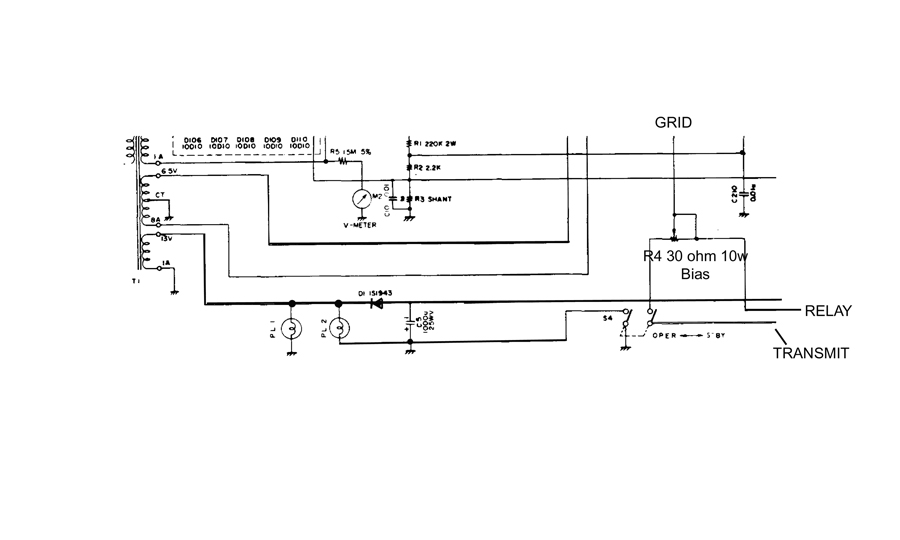
FL2100 bias system
Operating bias is developed by voltage drop of relay coil current through R4.
Standby bias voltage is open circuit voltage of T1, D1, C5 negative supply voltages, or about -18 volts.
D1 anode goes to relay coil
"Relay" is return from relay coil
"Transmit" goes to radio transmit closure line
Relay control voltage is approximately 18 volts negative at 120 mA, with a short ~100 volt "kick" upon opening.
Yaesu learned standby bias was not high enough in the FL2100B. Later versions of the FL2100, the FL2100Z, use a voltage tripler in the bias. While this is a great improvement the best method is still to let tubes seek their own bias by opening the cathode path.
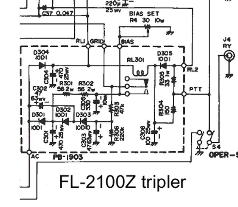
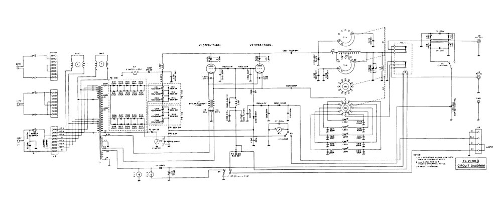
The FL2100Z has an overly-complicated three voltage power supply for control and bias.
Cut-off bias
Diodes D301, 302, and 303 along with capacitors C301 through C301 form a negative voltage tripler for tube bias. Approximately -50 volts bias is supplied through R303. This is adequate to cut off any tube, regardless of slightly lower production mu.
Operating Bias
On transmit, a divider consisting of R301,302, and R4 is connected. R301 and 302 connect to a "tap point" on the tripler where -18 volts is available. This divider supplies the operating bias. Bias is slightly unstable with grid current, and decreases the IM performance of the FL2100Z.
Control Voltage
+18 volts is supplied from D304. D304 is a half-wave rectifier filtered by C304, supplying positive "12 volts" for the antenna relay RL301.
Had cathode bias been used, only one supply would have been required!
The FL2100Z also hammers the radio control line pretty hard. It discharges a 220uF capacitor charged to +18V through a 33 ohm resistor, and a 100uF at +18V through a 150 ohm resistor into the radio every time the relays close. Depending on other resistances, the surge current into the control line can be as high as 650 mA on relay closure. This can damage small reed relays in some radios in a short amount of time.
An inexpensive 12V low current relay corrects the bias issue without complicated circuit or wiring changes. This circuit is normally not required in the FL2100Z, but it is absolutely necessary in the FL2100.
572b's are not well-designed tubes for RF systems. They are more like audio tubes in design. Click this 572B link and go to stability.
The FL2100 design uses a capacitor from the OUTPUT of the pi network back to the input of the tubes. A good design would NEVER do something like this. A pi-network transforms phase along with load impedance. As the tuning and loading controls are moved, and as the antenna load impedance changes, the phase of the feedback voltage changes. The output tuning and loading as well as the antenna impedance greatly affects feedback voltage.
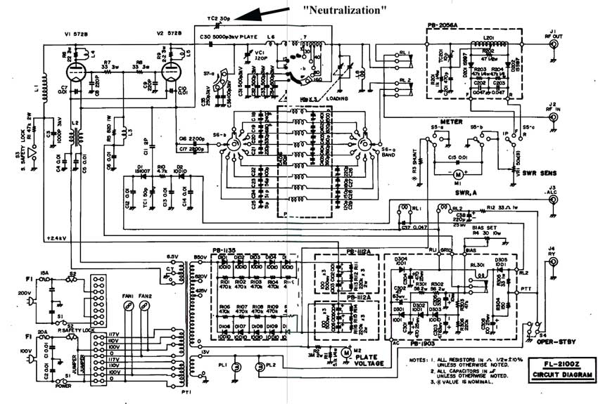
A good design would never neutralize or add feedback from the OUTPUT of a tank
circuit with a varying load back to the input.
This is because the load impedance as well as the setting of the plate and load capacitors will vary feedback phase!
Feedback phase should be a stable 180-degrees, but in this case it can range from -80 to -150 degrees depending on band and pi-network control adjustments.
When the antenna relay open, the LOAD is removed from the pi-network. This
INCREASES the amount of feedback by several times. The tubes, having less mu and
requiring more bias, are no longer in cutoff with the relay open and draw
current. This allows the tubes to amplify, and the greatly increased feedback
causes the FL2100 to oscillate on whatever frequency the tank is tuned to. With
no load, the voltage soars to many kV until the
bandswitch
arcs.
Changing tube brands in even a reasonably design amplifier is no problem at all. Changing tube brands (especially when a brand does not have the same characteristics) in an amplifier with multiple major design errors can be a big problem.
The Svetlana "fix" of increasing FL2100 bias is really not a " fix". It is a marginal patch.
Feedback
The most important "fix" would involve removing the capacitor from the output of the tank back to the tube input. This would disable the very poor feedback system. Neutralization page.
If the amp is unstable at upper HF, a neutralization system similar to that used in the AL-811H or AL-572B Ameritron could be used.
Bias
The FL2100 bias system should be rewired so the relay opens the filament center-tap return. Normal operating bias should be left on the grids. This would FULLY cut-off any brand of tube.
Another common failure, High Input SWR.
The tuned input circuit in the FL2100 series has capacitors that are very prone to failure. The problem is the wire bond between the internal foil and capacitor leads open, resulting in an "open-circuit" capacitor.
The "problem capacitors" are C211 through C219.
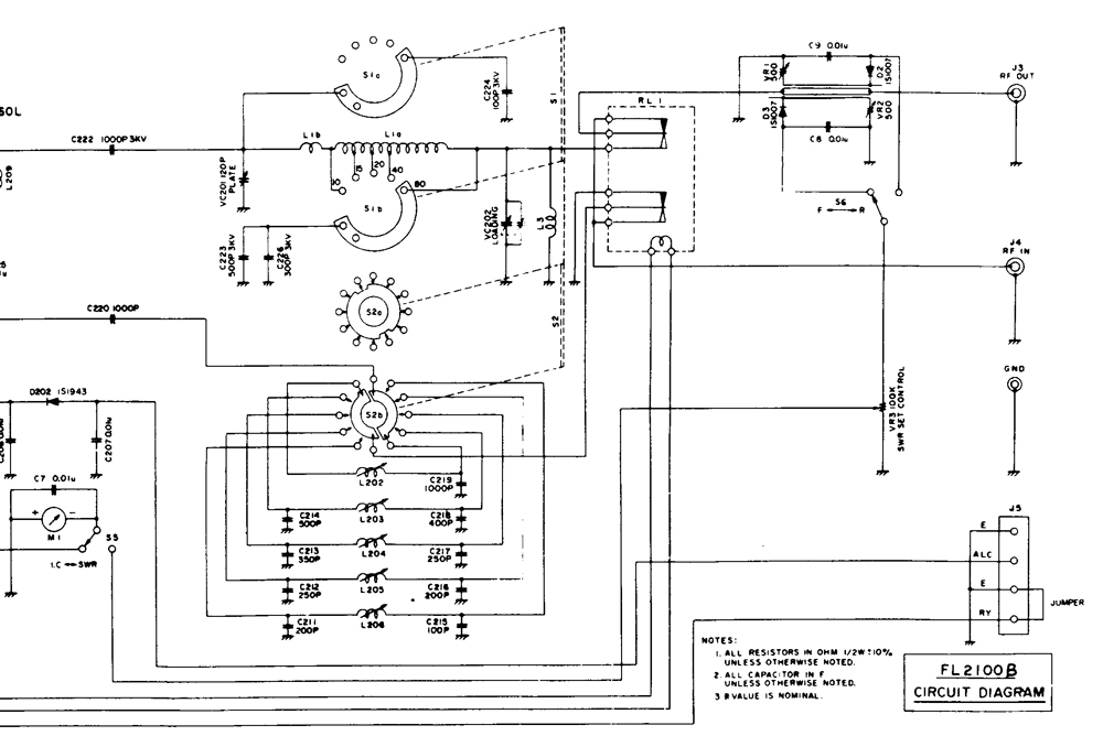
| C215 | C211,216 | C212,217 | C213 | C218 | C214 | C219 |
| 100 pF | 200 pF (180 or 220 pF OK) | 250 pF (220 or 270 pF OK) | 350 pF (330 or 360 pF OK) | 400 pF (390 pF OK) | 500 pF (470 or 510 pF OK) | 1000 pF |
Any silver mica over 500 volts dc rating is fine for these capacitors. I do not have any idea why Yaesu used such unreliable high-voltage capacitor. Voltage across each capacitor is only 150 volts peak.
Capacitors, if both are changed on any band, should be resized in the same direction for the same band. In other words if you substitute a 270 pF for C217, C213 (same band) should be subbed up to a 360 pF.