Holley HP Engine Control
This article is still under construction...in monthly editing (last rev 1/10/16)
The article was either hacked and deleted, or accidentally deleted, in mid-October. I am restoring it now
Jump to Holley ground loop design problem
I've used stock and clocked A9L and A3M ECU's, as well as the MegaSquirt PNP, in my Fox Mustang. I primarily used the Tweecer system with various software packages, and found it good for mild builds. The lack of failsafe, unreliable logging, and dependence on multiple external devices has made the Ford ECU system troublesome in high power builds. Just one small problem, like a loss of connection or even a hose failure, has destroyed pistons in a matter of seconds.
In an attempt to work around that, I used a J&S Safeguard. I really like the Safeguard. It is more than spark retard, it also has internal RPM limiters. While the J&S helped a great deal with failures like poor fuel, too much heat, or too much advance, the J&S could not prevent piston damage in severe lean conditions.
Problems with tunes and logging caused me to constantly add on devices. To solve the nagging log system failures, I added an AEM AQ-1 logging system. To solve air measurement system failures, connection failures, or tune failures, I designed and built an L-Warn system. That system monitored throttle position and sensor voltages, and shut the engine down if it was lean when throttle was more than 60% open, and ignored lean if the throttle was closing or a stage limiter was on.
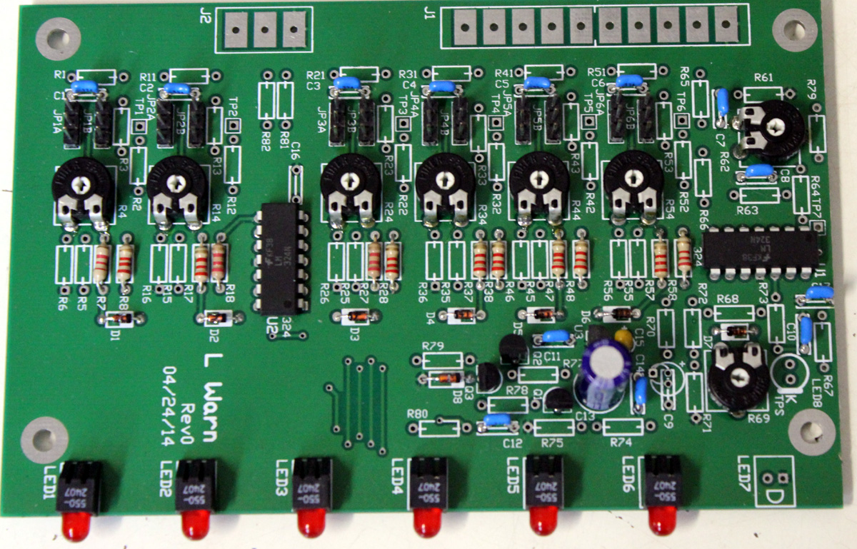
I did the circuit board layout, electrical design, and construction of my warning system here. This system bridges across the stock sensors, and watches the voltages for abnormal conditions. It activates warning lights when close to danger and a failsafe shutdown when danger points are exceeded. As a second function, this board also allows some standard gauges to bridge from EEC system sensors. It can sample voltage from the sensor for the gauge circuit without affecting the EEC use, allowing one sensor to drive multiple circuits without harmful interactions. My home made warning and buffer system looks like this:
Using the stock ECU with my 700-800 HP SBF engine rolled up almost $4000 in accumulated engine repairs, many months of down time, and hundreds of hours trying to learn how to tune or patch around problems. I have a mountain of books and papers on tuning, many of which put me to sleep trying to find something useful. The stock ECU required:
A MAF meter sized for power
J&S knock detector and external RPM limiter system
Aftermarket wideband O2 system that outputs logging signal or logs
Laptop in the car for logging or monitoring. Clicking on a "start logging" icon is a terrible nuisance in the staging lanes, and having a heavy laptop on the passenger seat is unsafe at high speeds
An external logging system, independent of the laptop, that always logged when making a pass (because service port logging was unreliable)
Learning which of a complicated flow of program tables and scalars were important, and which were not
"Saving money" by using the Ford ECU probably cost me $5,000-$10,000 and a year of fun racing out of the past 5 years. The good thing is the time I wasted using the stock EEC gave the Holley EEC time to develop and mature.
The Holley System
I initially worried about aftermarket system cost, and I did not want to cut my car up. It turned out the opposite was true. In reality, the Holley ECU system has been one of the best choices I've made for aftermarket parts. I use the Holley HP and Holley Digital Dash in concert with my own homemade instrument cluster.
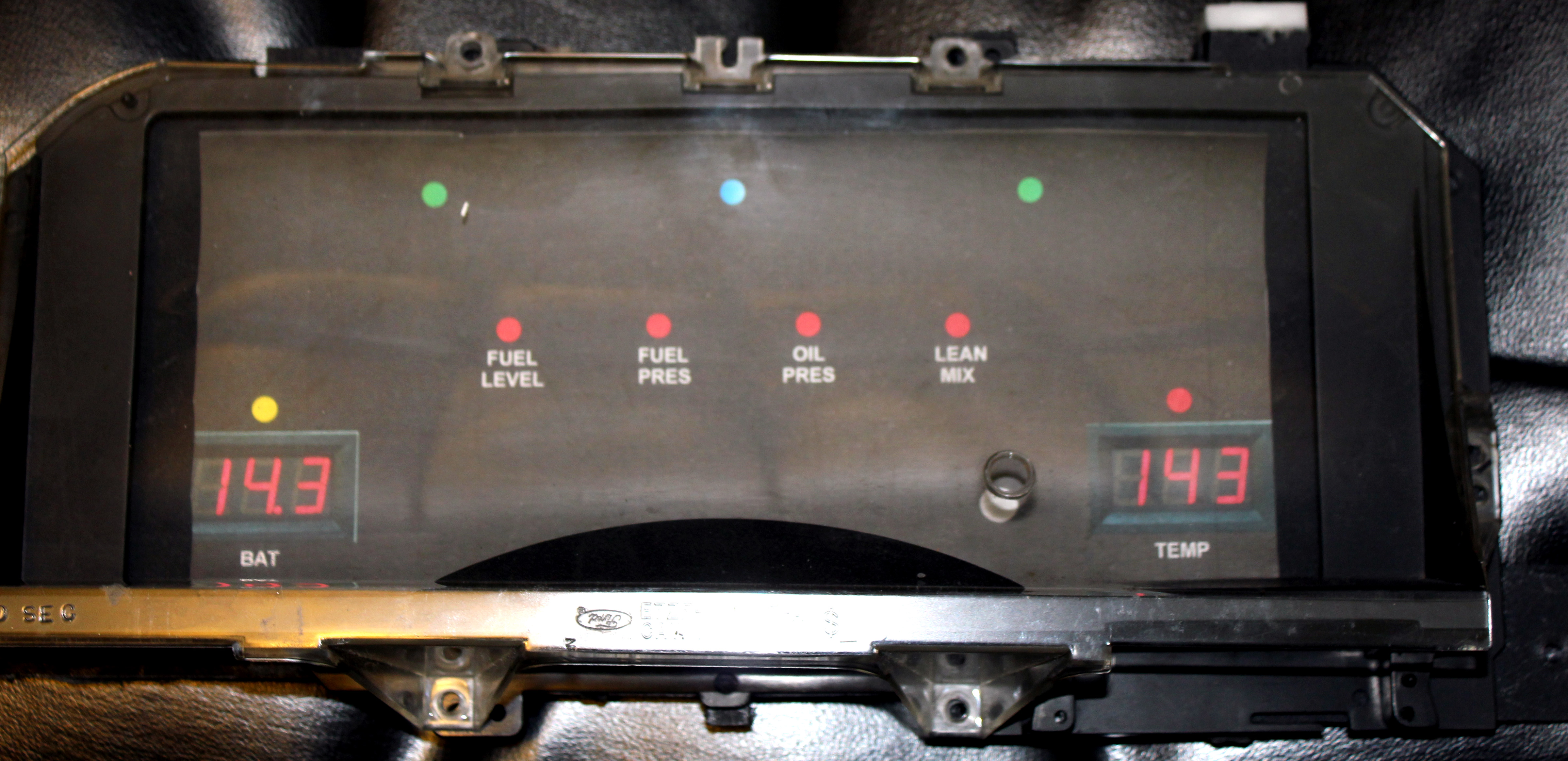
I decided to ditch my standard instrument cluster. With a Hughes Superglide style transmission, my car lost normal speedometer functionality. RPM range is well beyond the Ford factory tach, and I never had time to look down at gauges in a pass anyway. With the loss of most gauges, I opted to build my own cluster with two large digital red LED displays, six multi-color (off/red/yellow/green) LED warning lights, a bright blue high-beam indicator, and green LED turn signal indicators. I used the following layout:
I still use an analog tach with super bright RED LED shift lights (on the right side of the tach), along with an analog boost gauge. There simply isn't time to watch any other gauges, mandating warning lamps for lean, fuel pressure, fuel level, proper boost (staging), and shifting. My homemade instrument cluster does not illuminate unless a problem or alert appears.
One example of a warning is battery voltage. With a 12V battery, 12.6 volts is a fully charged float voltage, and anything from 12.5 to 13 volts turns the battery warning LED off.
Less than 12.5 indicates some loss of charge, illuminating the red/green battery LED with a mix of red and green to produce yellow. The yellow turns progressively redder (by reducing green) as battery sags below 12 volts.
If the alternator is charging or supplying adequate power to run the vehicle, the battery LED turns green. At 14 volts and above it is bright green, because that means full charging. At 14.9 the LED goes blinking red, indicating dangerous overcharge (regulator or battery boiling).
With a glance, I know my battery and charging system function.
My car's cooling fans and pumps run in the accessory key position. My battery indicator logic design disables the accessory key position if battery falls below 11.9 volts. This disables cooling fans (and radio) if the ignition key is left on accessory to operate fans and water pumps for cool down before the battery becomes too low for restarting the engine.
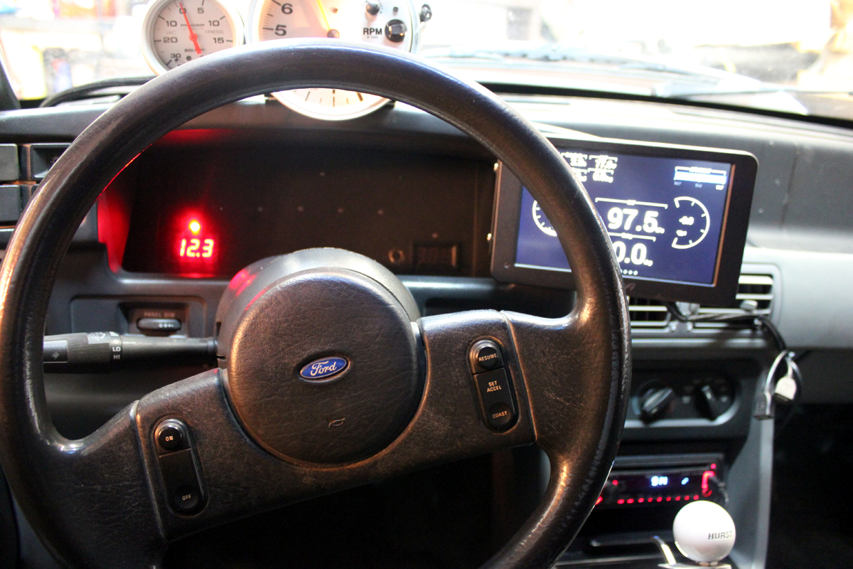
The dash layout looks like this when installed. This is with key on, engine off. In the picture below, the battery has dropped below 12.5 volts causing a red warning lamp above the battery voltage. The Holley digital dash wiring is not in the final location in the picture immediately below:
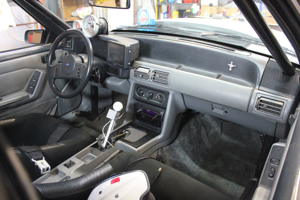
Final wiring is seen below. Wires from the digital dash route through the dash vent to the Holley:
My Holley system mounts on a plate behind the glove box:
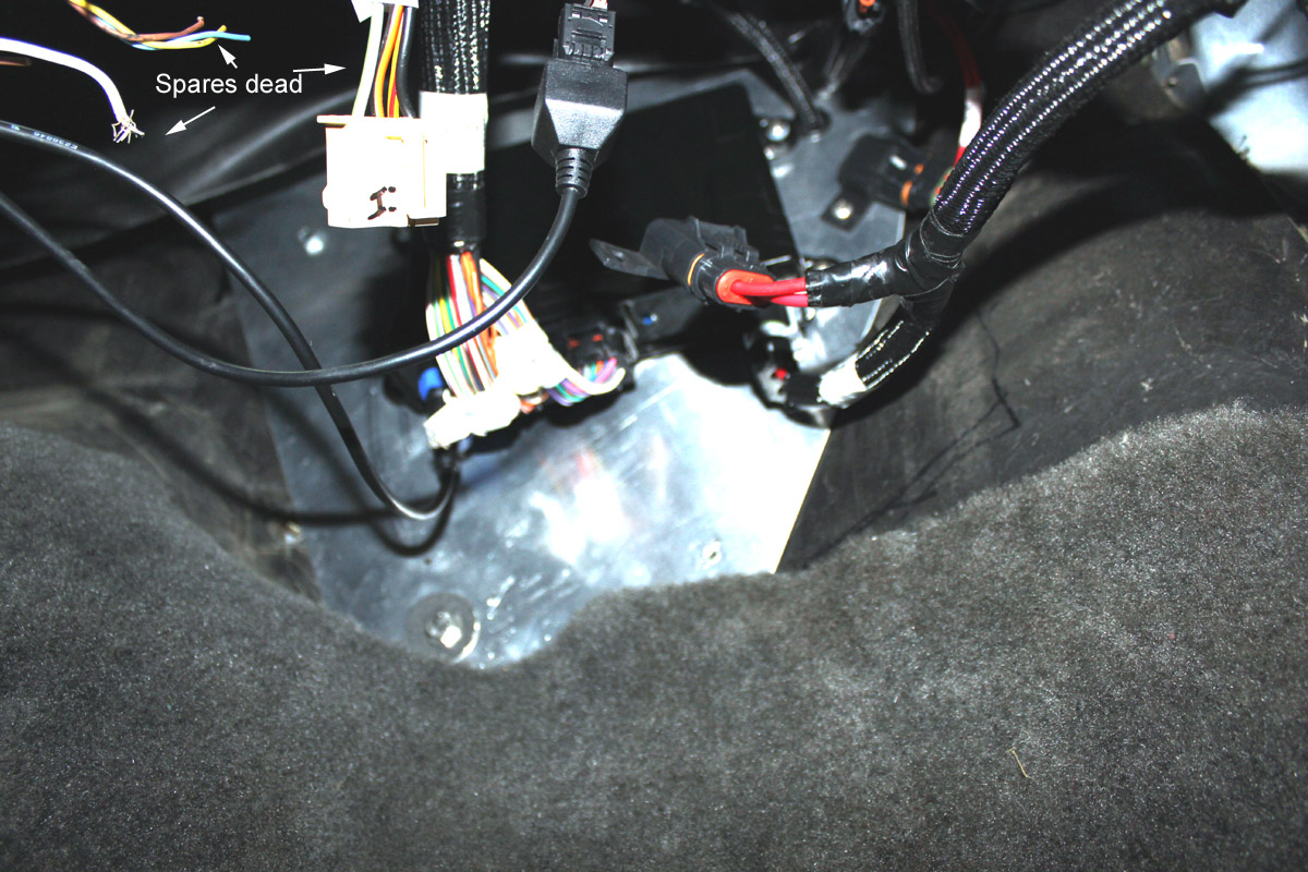
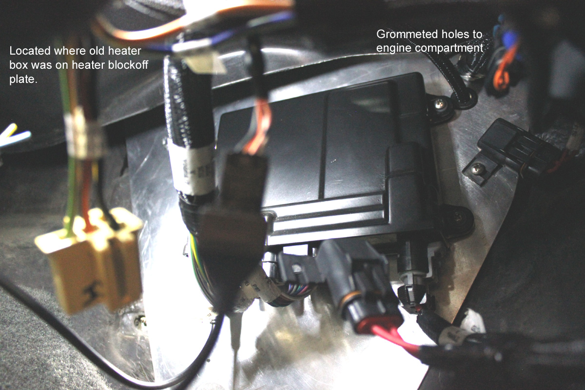
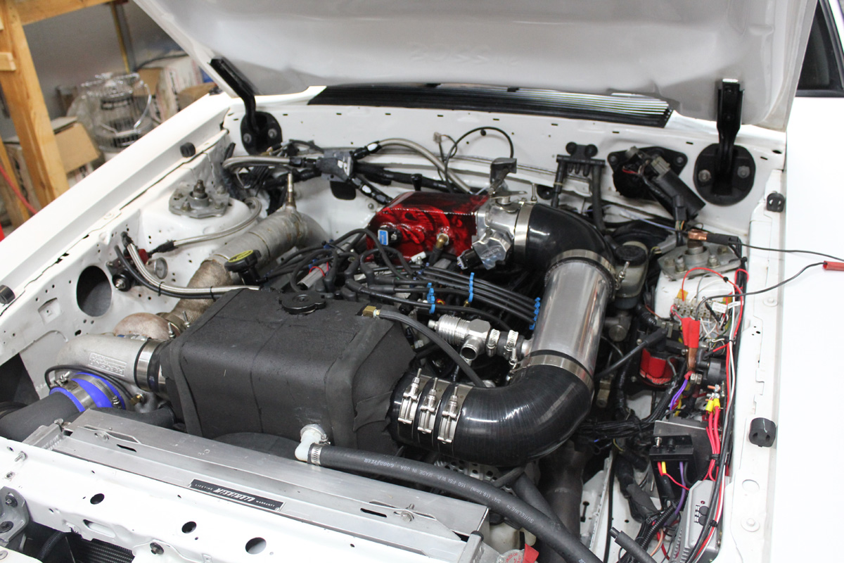
Since I want to run fans and cooling pumps with the ignition run off, I do not use the Holley for fan or water pump control. Wiring in picture below around the fan controllers and ignition box cannot be harnessed yet. I have a temporary Flex-a-Lite fan controller (since removed and replaced with a Derale) hanging on the bracket while I wait for a Derale replacement controller. The Holley HP harness enters the engine compartment through grommets by the PS hood hinge:
Despite following Holley's instructions to the letter and using Holley harnesses, my Holley HP would not work properly. The problems were:
In the version I have (summer 2015), Holley mislabels PSIG (or the commonly used PSIG we call "PSI") as PSIA. PSIA actually starts at zero for perfect vacuum, atmosphere is ~14.7 psi, and 20 lbs. boost would be 34.7 PSIA. Holley actually uses PSIG (called PSI on the street). PSIG has a negative number for vacuum, atmosphere is at zero psi, and boost is a positive number greater than zero. Naturally, when I programmed things based on PSIA, all sort of bad and confusing things happened. Once I learned PSIA was a label mistake by Holley, and it actually should be PSIG, all went well.
Holley has some serious ground loop problems in the TFI harness, and in their wiring instructions. Holley is very firm about wiring the power ground to the battery, but that actually is a very unsafe thing to do. Wiring to the battery negative also aggravates ground loops, opposite of what people think the battery negative would do. I'll explain this below, because this problem actually extends outside the Ford TFI system.
The Holley fuel cut limiter is useless. The engine RPM oscillates wildly over a wide range.
Fortunately, once understood, the first two problems above were easy to correct. The fuel cut issue is in the Holley programming, and Holley must correct it.
Holley Ground Loops and PIP / Spark Trigger Issues
I assumed my first dyno test of the Holley would a success, since I used the OEM Ford TFI distributor and ignition system quite successfully with 15 psi boost at 7500 RPM with Ford's EEC-IV (both A9L and A3M) system. My first Holley dyno pull at 10 psi with the Ford TFI interfaced to the Holley was completely unsuccessful.
Using the Holley system and Holley harness adaptor with the Ford TFI distributor, my car would not pull over 5500 RPM without spark scatter and spark drop. The effect was much like valve float or spark blowout, or an RPM limiter. A quick switch to an MSD 6AL style CD ignition box only allowed 6000 RPM before the same symptoms appeared:
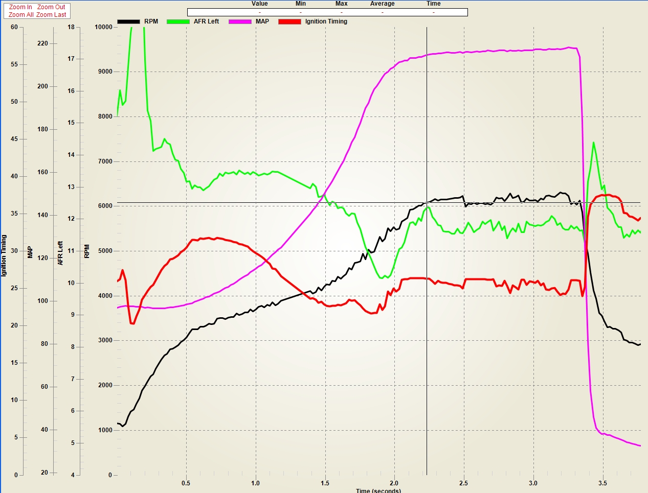
Testing the Holley RPM limiters, the fuel cut caused wildly varying RPM. The spark cut was scary, it caused terrible backfire banging and popping. The spark cut noise sounded like a cannon going off, and I feared for severe turbo, engine, or piping damage. I initially assumed this horrible behavior was due to a poor RPM limiter algorithm. A storage oscilloscope test showed the ignition spark problem was from false triggering of the ignition by ground loop noise induced into the Holley PIP input.
This ground loop problem was traced to three things:
Holley instructions and labels insist customers connect the black negative chassis ground and power lead to the battery negative, yet that negative is the ONLY chassis ground and signal ground for the Holley. This is a very serious mistake
Holley uses a long small gauge harness wire for the distributor PIP signal input return, and that return is grounded at both ends. This is a minor mistake
Ford connects the PIP and TFI grounds to a distributor pin common to the engine block. This is perfectly acceptable if the EEC has a differential input for signal, but the Holley uses a very poor single-ended input that is common grounded to the negative power bus and chassis of the Holley
I initially followed Holley's instructions, and grounded Holley power (and chassis) to the battery negative. I normally would not do that, because my training and experience is that accessory device negative connections must never connect to the battery negative post, battery negative terminal, or share a common bolt or fastener with any factory battery ground.
As a matter of fact, European regulations for mobile communications, audio, and
ancillary amplifier equipment that I design and/or write instructions for
specifically prohibit connections to battery negative posts or battery negative
cables! Battery negative connections are prohibited because of vehicle fire and
electrical equipment damage concerns.
| The only battery post negative connection should be to or from another battery negative, the vehicle chassis, and/or the engine block. There should never be a direct negative post path to accessory or ancillary equipment. |
The sole exception to the rule above would be if the negative
bus in the connected device does not have a path to ground through any
connections, including the chassis or cabinet, although a battery negative
connection still would be prohibited in European countries in CE regulations.
One exact European regulation is:
| 4.6.4.
Negative Feed Connection In the case of negative earth return vehicles, the negative power line should not be fused. It should be connected to the vehicle body as close as practical to the point at which the battery-to-body connection is made. Do not connect the negative power line directly to the battery. For heavy commercial vehicles (>7.5Tonne GVW) only, and those vehicles with tilting cabs where the cab may be isolated from the chassis by rubber mountings, a ground point is provided by the vehicle manufacturer within the cab to provide battery to cab grounding. Generally this is located within the main fuse box. It is recommended that this point be used for installations in this instance. With certain equipment it may be necessary to connect the negative supply line to a local earth point. In this case an existing vehicle earth point must be used. |
If Holley had followed the same directive that applies to European ancillary equipment, one that Ford also uses, they would have a safer installation!!
Ford TFI/PIP/EEC Power
Ford avoided ground loops in Fox Mustangs by using a "chassis-centric ground" for all electrical systems except the starter, alternator, non-critical engine sensors (i.e. analog instrument cluster gauges), and TFI ignition coil primary ground return. Below you see a Ford OEM negative pigtail. The negative lead below uses the large heavy cable for block-common-ground devices like the starter, alternator, and other engine-grounded devices. The smaller lead supplies battery negative to the vehicle chassis, which is the common ground for signal and low-noise load grounds. The EEC harness ground, which has some noise from injectors and other switched devices, returns to the vehicle chassis very near the front-mount battery.
With Ford's wiring, should the battery connector or any ground open or go high resistance, there is little fire risk or damage risk to electrical system hardware or components.
If we examine Ford's wiring, we see Ford complies with the European directive (even though the directive applies to aftermarket accessories, and not to OEM equipment). Ford connects the EEC as close to the battery chassis ground as possible, and not to the battery. The only Ford OEM connections to the battery negative are the vehicle chassis and the engine block. The Ford EEC harness ground is a good idea because the battery terminal, the engine block, and the chassis grounds are all close together, and the battery negative is off by itself.
WARNING: This would not apply to a trunk mount battery, because the trunk is too far from the engine block for a reliable low-noise EEC ground or low resistance starter or alternator wire connection ground.
The overview of the Ford system is:
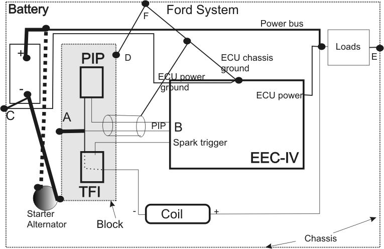
Ford uses the chassis (C) as ground reference for all loads (E, F) except things grounded directly to the block (A). Ford does this for noise reduction and ground loop avoidance. The PIP signal enters an EEC-IV differential input (B) through a shielded wire pair. Traditional noise shielding and mitigation dictates grounding at a noise source and shielding at the noise source area. The distributor cap, with high voltages and constant internal arcing, is the major electrical noise source. The distributor base ground and the foil shield eliminates electric field coupling into the PIP wires, while the use of paired PIP wires to a differential input eliminates magnetic field noise coupling into the PIP, as well as eliminating ground loop coupling from the block ground on PIP wires. The block is grounded two ways, to the battery negative through a very large short length cable because of high currents and noise, and from a head (D) to the firewall (F) near the computer chassis ground.
Ford is block-centric for high current sources and loads that originate high level noise, and chassis-centric for all other power sources. All voltage and noise critical sensors and triggers are only grounded at one point, the other end of the path is differential between the wires. The chassis is the best noise-zero ground. The only connections to the battery negative should be (and are) the vehicle chassis and/or the engine block. Grounding any accessory device to the battery post increases likelihood of damage and noise problems.
My TFI spark break up and RPM limiter issue (that could have damaged the engine had I used it) was completely cured by ignoring Holley's advice. I removed the Holley negative wire from my car's negative battery post, and grounded the Holley power (which is also the Holley chassis) at the firewall near the old Ford ground point. This point is within a foot or of Ford's OEM passenger-side cylinder-head ground point.
I considered a block ground for Holley power. I decided against it because my engine is on rubber mounts. I did not want a connection between very high starter and alternator currents and the Holley chassis if the block should ever develop a high resistance ground.
From Holley Instructions, the very first Holley "Do" sets the system up for damage and ground loops:
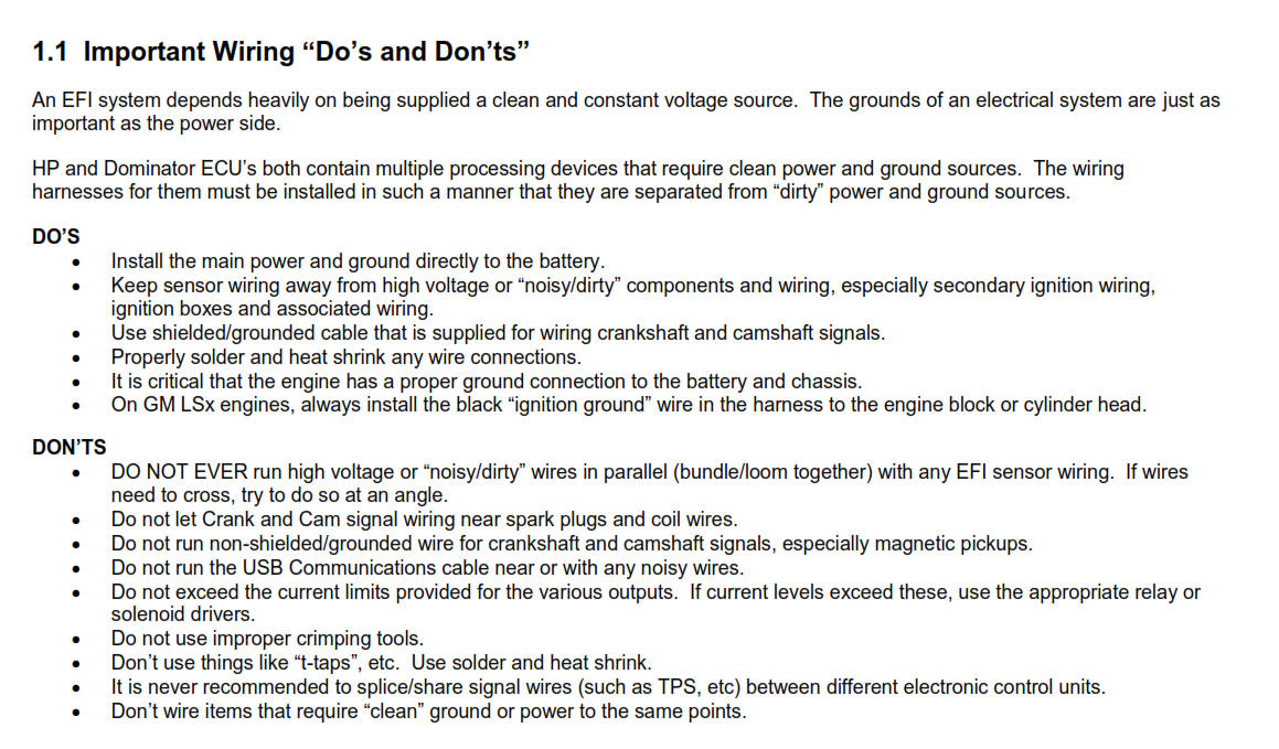
There are two problems with Holley's instructions shown above:
First, a power ground should never be connected directly to a battery negative. Grounding to the battery creates an equipment damage and fire hazard. The only things that should ever connect to the battery negative are the vehicle chassis and the engine block, or another battery. The reasons for this are described at this link Battery Negative Lead If a battery negative lead to block and chassis ever goes high resistance or open, all of the vehicle current will try to run through the ground of any device connected to the battery negative. This could cause a fire, or damage the Holley or things connected to the Holley. Holley is setting users up for failure.
The second issue is the Holley TFI wiring harness that Holley sells actually violates some of Holley's "Don'ts". The PIP wires in the Holley TFI harness are not shielded, the TFI PIP ground is a chassis ground that is grounded at both ends, which sets the TFI system up for noise and ground loops. I'm not sure if things like this occur with wiring or adapters for other systems, but the TFI harness is a recipe for disaster. This is especially true when using a battery negative post ground to the Holley chassis, because of the battery negative to chassis to block ground loop.
Holley gives a very bad ground "Do" that can cause damage and ground loops, and Holley sells harnesses and uses inputs that violate their very own "Don'ts".
A proper correction for the TFI PIP would be a differential input at the Holley for the PIP, like Ford uses, as well as a chassis ground reference for the EEC/ECU system and negative power. The positive connection does (and should) connect to the battery, but a fuse belongs at the battery. A fuse at the engine control does not protect the vehicle from short circuit fires between the battery and fuse.
I did not do a proper correction, because I got away with just grounding the Holley to the firewall near where the head grounds. I could easily make a differential input buffer for the Holley PIP input. This would improve any spark trigger, as well as the PIP system, by reducing noise. I could have also used a twisted pair inside a shield for the PIP signal, which Holley should have also done. I got away with not rewiring anything, or cutting up a new Holley harness.
Based on what I have seen with my vehicle, following Holley instructions could result in engine or electrical system damage. This is a great system, it's just too bad someone does not understand ground loops and wiring (and fix the fuel cut algrorythm).