| Hi! If you arrived from an eHam article link, please read this carefully. If you read carefully, you will find this page actually does not, and never did, say what the eHam article tells you this page says. I accented important areas to make it easier to spot misrepresentations of this page's contents. It's my belief that some people just like to argue for the sport of arguing, even where there is nothing useful to be learned or gained. To enjoy the sport of arguing, they sometimes find it necessary to alter what other people say. They also reach conclusions not supported by evidence or fact, like the following quote from the eHam article:
If you look carefully at the eHam article, you will not find anything supporting that conclusion. As a matter of fact I can offer solid evidence that proves that statement is wrong, and I am willing to wager money on it. It is more than a little silly to say "[a]ny 75m air-core loading coil must necessarily be in the ballpark of 30-45 electrical degrees long". Is every antenna the same? Is every loading inductor the same? Anyone can write an article and claim:
Generally when someone says "here is the test setup", they describe in detail and/or show detailed pictures of the test setup. They also generally offer a screen shot or print of data. Without knowing many details, such as test fixture design and measurement equipment, we really don't know what was done. An EZNEC graphic is not a test setup! Also, there is little value to any of this to anyone building an antenna, except guidelines or suggestions I highlighted in color below. Thanks for visiting my website, no matter how you got here. Please feel free to email me by using my callsign at w8ji.com with any suggestions for improvement. I may not always answer, but I always read, and try to implement any suggestions, or correct any errors. |
Time Delay through Inductor
Many people visualize current, in a small loading inductor, as starting at one end and traveling through the conductor turn-by-turn. It is this visualization that causes us to conjure up all sorts of untrue ideas of what a loading inductor does. One example is where people think an 80 meter vertical needs 67 feet of conductor length to make a 1/4 wave vertical, so they wind 67 feet of wire (one quarter wavelength) around an insulated pole just a few yards long. One way to prove or disprove the perception current travels through the conductor turn-by-turn is by examining time taken for current at one end of the inductor to "appear" at the other end.
The sample inductor in this test is a typical 80-meter loading coil. It is 100 turns, ten turns-per-inch, and 2 inches inside diameter. The wire is tinned #18 buss wire. Inductor Q measures 290 at 4 MHz on an HP4101A, and on an Agilent vector network analyzer. This is a reasonably high Q 80-meter loading coil.
We know many things about this inductor right away, based only on physical dimensions. We know conductor length making up the coil is about 53 feet. We know light travels at 982,100,000 feet per second in freespace. We know physical length is 10 inches, plus about one-foot of total connection length in my open-air test fixture. We also know the very fastest speed electromagnetic energy can travel is the speed of light in freespace, other things like nearby dielectrics only slow it down.
If current winds through the conductor length, time delay should be about .98 nanoseconds per foot of conductor length. Time delay would be 54*.98 = 53 nanoseconds.
How long does it take current reach the other end of this inductor? Here's a plot of time delay at various with frequencies:
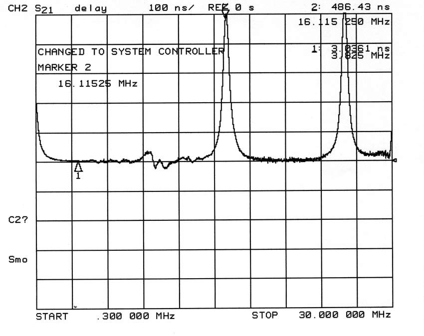
On 80-meters, and actually over a fairly wide frequency range, time delay is about 3nS. 3nS is equivalent to 3.06 feet of distance. We know one foot is occupied by the test fixture connections, so the ten-inch long inductor appears to be about two feet long, so far as current propagation delay.
How does the current travel through the inductor so fast? After all, the wire is about 53 feet long.
At first this seems impossible, but the answer is actually quite obvious. Time-varying current gives rise to time-varying magnetic flux. This magnetic flux, since conductor spacing is close and distance very small, links each turn very tightly to the adjacent turn. The rapidly changing magnetic flux causes charges to move in the adjacent conductor. The changing magnetic field couples through all the close-spaced turns with very little time delay. It is this magnetic flux coupling that provides the primary mechanism for energy transfer through this inductor, and the path is much shorter than the circuitous and much longer path along the conductor.
The above measured data, shown in the screen capture above, shows time delay of current is very close to zero.
Current at BOTH ends of inductor, when there is no shunting capacitance present to increase phase shift, lags voltage at the source-end by a value that depends on system termination impedance and the inductor's reactance! Without shunting capacitance throughout the length of the inductor, current would be equal at both ends and phase delay would be zero. In the case of an inductor, voltage is out-of-phase with current. Voltage leads current at the generator. Current lags the generator voltage an equal amount at either end of the inductor, even though delay time is finite, unless we have shunting capacitances and imperfect mutual coupling from end-to-end of the inductor.
If the inductor in this test were an ideal inductor, time delay would be just under 2nS in this test system. Since it is less-than-perfect and does not have perfect flux coupling, and because it has stray capacitance to the fixture groundplane, time delay is longer (about double) than we might expect.
Depending on shunt capacitance, termination, and mutual coupling from turn-to-turn, overall system time delay can vary. A compact lumped loading coil does not represent a certain fixed number of missing antenna degrees, it simply cancels reactance. The very best loading coils, mounted in the best positions, have the least current taper and current phase delay from end-to-end.
The important point is current does not slowly wind its way through the loading coil turn-by-turn, and a loading coil does not replace a certain number of "missing" antenna electrical degrees. Mutual magnetic coupling from turn-to-turn tries to make charges in the inductor move at nearly the same instant of time. Flux leakage and shunt capacitance do the opposite, they allow, and even encourage, delay. The better the loading coil and system design, the more uniform current distribution is, and the less time delay occurs.
This is why, with a base loading coil in a well-designed system, current is equal on each end of the loading coil. Phase delay of current is also essentially zero. Only voltage decreases and changes phase along the length of the loading coil. The essentially equal currents at each end of the coil are also true with large capacitance hats, or with long whips above the loading coil. In such cases, termination is primarily by shunt reactances at the open end of the inductor. A large current taper though a loading coil indicates the system is poorly designed, and that displacement currents are robbing the upper areas of the antenna from current. This reduces effective antenna height and radiation resistance.
Conclusion (new)
The bottom line, with very high reactance coils, is we should keep large loading coils away from anything that increases capacitance shunting the coil. This means the coil should be away from sheet metal, and capacitance hats kept up away from the coil.
Mobile and other Inductors Page
since
3/11/2006