NDB and Fish Net Beacons
|
NDB and Fish Net Beacons |
|
modified June 12, 2012 added pictures and deleted PUN frequency data
NDB SignalsNon-Directional Beacon or NDB 's are generally low to medium power transmitters. They are often in 25-100 watt power range, although in certain applications some can run kilowatts. With good antennas and low noise, NDB's can be heard over very long distances. Here's a recording of "OS" from Ohio to Georgia on 515kHz! All of the airport or aviation NBD transmitters I'm aware of operate below the USA Standard AM Broadcast Band of 530-1700 kHz. NDB's are found near but not necessarily at airports of all sizes; ranging from grass strips to large International Airports. NDB transmitters can be used for other applications, so they are not necessarily airport related or on an aviation NDB frequency. The primary low frequency aviation Radio Location Band in the US and Canada extends from 190-435 kHz, although there are licensed NDB's on other frequencies. For example 510.525kHz is a valid FCC issued RLB channel falling under Part 87 Aviation Service rules, and Canada (link) has 510-535 kHz listed as a radio location band in both Canada and the USA. NDB transmitters may or may not have an identifier or callsign that represents the associated airport. Often there will be no obvious association with an identifier and the airport or area of the beacon. For example the dirty, poorly-adjusted, NDB transmitter at Peachtree City, GA repeats the identifier "FF". If we look up "FF" at this link Beacon Search we see no obvious name or callsign association with Peachtree City Airport. This is true for many NDB systems. There also are duplicate identifiers or calls listed, such as CO. The Peachtree NDB has all the signs of typical misaligned or poorly designed and improperly maintained beacon. FF at this time of monitoring (Feb 11, 2007) has: 1.) Negative carrier level shift on 316 kHz when the ID tone comes on. This can also be interpreted as image or negative keying. 2.) Spurious modulation products caused by overdriving the system including desired modulation tones at 315 and 317, with undesired illegal level spurious tones at 319, 318, 314, and 313 kHz. 3.) Excessive harmonic levels on 632kHz and other frequencies I'll explain why and how problems like this commonly occur. Transmitters like these are an interference problem waiting to happen, and this is why people have logged dozens of transmitters at great distances on harmonics as high as the tenth harmonic, and higher! I've personally logged 25-watt NDB's on the 11th harmonic at distances over 2000 miles! So much for FAA approved test methods and avionics service tech quality! No other radio service would think of using an oscilloscope to look for harmonics. NDB TransmittersNDB transmitters are mostly modulated by keyed Morse code audio tones, but a few are also voice or digital telemetry modulated. Keying is at a slow speed and generally repeats a two or three letter group endlessly at slow speed(mp3 file) with very even spacing. They transmit without the excessively long pauses of silence, and the intermittent long carriers, characteristic of fishing beacons, although images of NDB's can appear to have nearly constant carriers with gibberish CW. A larger airport NDB might include weather or other airport information like altitude or barometer readings in standard amplitude modulated voice, often this appears as a single voice sideband with carrier. Here is a 160 meter harmonic of PUN, and BEQ. I have logged NDB harmonics on 160 meters from as far away as Arizona and California!
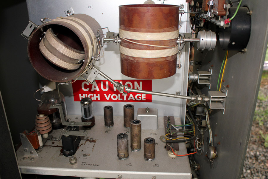
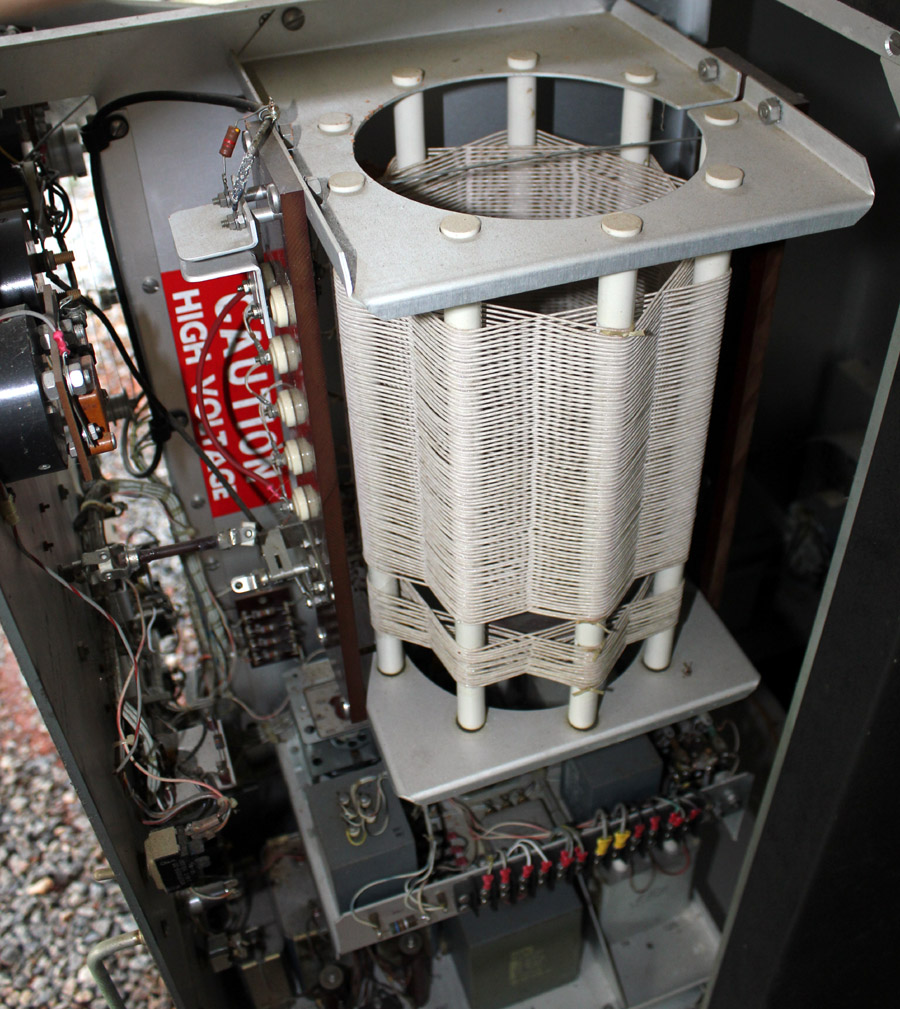
Output filter and loading coil
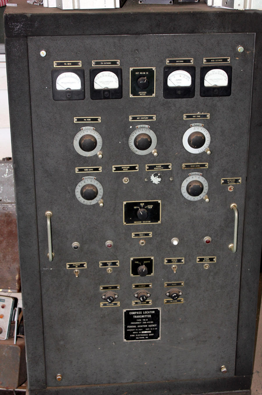
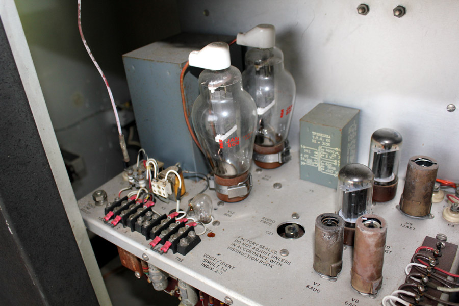
Transmitter ConstructionWhile NDB's, like the unit above, were initially high-quality plate-modulated AM transmitters with excellent harmonic filtering, the recent trend towards "cheap is good" by manufacturers has resulted in many problems with NDB transmitters. I've seen and worked on a few NDB transmitters over the years, and even parted out a few retired units. The unit above uses a pair of 809's to plate modulate a large class-C beam power tetrode. The big design flaw in most modern NDB transmitters is the use of low-level modulation, followed by multiple linear stages with semiconductors. While a low-level modulated system avoids expensive high-level modulation circuits, it depends on multiple stages to be perfectly linear. Worse yet, most transmitters use little- to-no harmonic suppression throughout the stages. They are built nearly like a broadband audio amplifier, depending almost exclusively on an external ATU (antenna tuning unit) for suppression of harmonics. Transmitters almost always employ a MOV or zener diode clamp for lightning suppression. Even if the transmitter had some provisions for harmonic suppression, it would only take a high SWR or a bad component to generate harmonics in an otherwise perfect transmitter. Even with a properly functioning ATU and lightning protection clamp, a bit too much drive level, or a defective component in earlier stages, will generate excessive harmonic levels. The FAA and NDB transmitter manufacturers nearly always require use of a simple, but unreliable, oscilloscope to determine proper adjustment. This is something any RF engineer would laugh at, since excessive harmonics can occur without a noticeable or obvious flaw in the sinewave displayed on a conventional oscilloscope. This is why other services use spectrum analyzers, or better yet calibrated field strength meters, to verify harmonic performance. Negative Image ID or CW of NDB (non-directional beacon)Anyone familiar with multiple tone testing of linear devices will immediately grasp the reasons behind the negative CW image that sometimes occurs from overdriven linear stages processing a tone modulated signal. It is a common effect when dealing with distortion products or non-linear devices processing complex waveforms. A negative image is somewhat difficult to grasp, unless we look at how the signal is processed in the transmitter. An NDB transmitter is like any low-level amplitude modulated transmitter. It is a modulated stage, followed by multiple linear amplifier stages. When drive to "linear" stages is excessive, subsequent stages become non-linear. Later stages go into gain compression or clipping. The effect of gain compression is the normally steady carrier level is greatly reduced when the MCW (modulated CW) tone-modulation appears. Some, or most, of the power normally available for the carrier goes into the sidebands. Because the stage simply hasn't enough available power for the modulation and the carrier, the carrier level decreases when modulation appears. Another way to look at this is with a Fourier or "Harmonic" Analysis of the output waveform. Any waveform other than dc or a pure sine wave is really comprised of multiple sine waves of varying level and frequency. When modulation is applied the clipped or saturated stage or stages changes the RF waveform, and this changes the spectral distribution. The fundamental or carrier is reduced as energy in harmonics and distortion products increases, and this is why we hear a negative carrier level shift. You might hear either the modulation product on a harmonic or the carrier, or both. The carrier might be stable or it might shift amplitude with modulation, and it can change level any amount. Here are two samples of reverse image harmonics, caused by an overdrive or over modulation, on 160 meters. Illegal image of NDB, and another illegal image. Drift Net or Fishing Buoy TransmittersThese transmitters send periodic identifiers that repeat. Generally they repeat with three ID's, followed by a long steady carrier, and a very long pause of no signal. They are battery powered and low power, but they can be heard for hundreds or thousands of miles. They are most frequently found between 1.8 and 3.6 MHz, and are very common on the 160-meter band. This particular unit is manufactured by Ryokuseisha, in Japan. It features DSS transmitter frequency control, runs about five watts output (measured), and is remotely programmable via a marine band radio link using a receiver inside the unit. Data appears to be sent via four tones of 592.5, 652.5, 712.5, and 772.5 Hz.
The identifier has nothing to do with the location, it is programmed by the manufacturer, installer, or by the fisherman with adequate technical support. This transmitter contains a receiver, and can be turned off and on remotely by the owner. The most effective way to get rid of one is to operate on, or very close to, the beacon frequency. It takes some period of time, but if the owner can't hear the beacon reliably he will program a new frequency. Several nights of heavy activity near a beacon often results in a channel switch. The same is true for illegal fishing vessel voice communications transmitters. Illegal marine operations often occur on 160 and 80 meters. The fishermen often coordinate operation on or near a beacon's frequency using USB. They often take the hint they are operating illegally when they hear legal activity on or near their frequency. It isn't always the Japanese or Korean boats that are problem, there are fishing boats based out of Canada and the United States operating on illegal frequencies.
|