There are a few automotive cooling myths. Probably the worse and most popular myth is that removing a thermostat will make water flow too fast to cool. In reality, unless flow becomes grossly turbulent through significant areas of the system, the more flow the better the cooling becomes. I can't imagine an automotive system ever coming close to that point, with the sole exception of grossly excess water pump speed causing cavitation and reducing flow.
Cooling System Basics
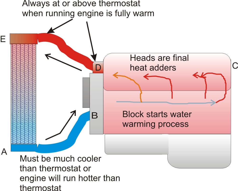
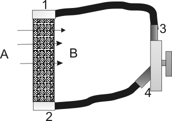
Typical USA water cooled engines flow like this:
Cool water is drawn from the radiator outlet tank (A) into water pump (B).
The pump (B) pushes cool water into and though the block towards the rear (C). Strategically placed "steam holes" allow some water to flow past bores up into the head. These holes keep water moving around the cylinders. The small gasket holes promote even bore warming and prevent trapped steam and air pockets. This is where most heat is added to the water.
The cylinder head (C) returns water to the thermostat housing (D). The cylinder head is the least critical for temperature changes. This is the last place where heat is moved into the water.
The thermostat (D) closes when below the rated temperature.
This restricts flow to a small bypass hole. Greatly reduced water flow rate
causes
water temperature to rise. There must still be some water movement. The water movement,
even with the thermostat closed, must be enough to prevent hot spots and
promote evenly warmed cylinder bores and heads.
The
thermostat opens and provides full water flow at a predetermined
temperature. Thermal lag in system stabilizes engine temperature around the thermostat
temperature opening threshold.
Water from the thermostat flows into the radiator's hot tank (E). This is normally a high spot on the radiator. This is normally a high spot because hot water is less dense. The warmer water rises while cooler water sinks. This is called "convection".
Water from the radiator inlet tank (E) is forced through many small hollow tubes. The tubes have fins attached outside to increase air contact area. If you examine the construction you will see the air surface contact is many times larger than the water contact area. This is because water has a much higher heat capacity than air. Water even has a higher heat capacity than metals, water's heat capacity being several times than that of aluminum (pound for pound)!
Air flowing through radiator fins is intentionally made turbulent. The turbulence helps the air scrub heat from the metal radiator fins. The air absorbs heat from the water, cooling the water.
Water flow is restricted to increase temperature, water flow
is increased to reduce temperature. All flow controlled cooling systems work this way.Thermostats
reduce flow below the target, and progressively open wider near or above target.
The radiator cold tank always has to be below
target temperature or water will not be able to cool the engine to target. The
ideal way to control fans is by monitoring the radiator cold tank. Early cars
had no fan control, but in the 70's thermal clutch fans became popular. Thermal
clutch fans would spin slowly, pulling a radiator temperature air sample across
the clutch. When that radiator sample reached a known target, usually 10-40F
below the thermostat, the clutch would fully engage. Modern sensors and
electronics allow direct monitoring of the cold tank and variable fan speed
control through PWM (pulse width modulated) electric fans.
This
doesn't mean controlling the fan from cold tank temperature is the only
way, it is just most reliable and accurate method. It is
also possible to monitor engine outlet temperature. Engine outlet temperature,
especially if data includes engine operating conditions or fuel consumption, can
be used for fan control. For example with a 200F
thermostat, when
engine water outlet exceeds the 200F target, a fan system can be started. This
is perfectly fine for normal light or steady load systems such as small
passenger vehicles with smaller engines, because they don't have extremely high
BTU thermal spikes. A smaller capacity system also has little thermal response
lag.
Heavy duty systems, such as trucks or high horsepower vehicles,
have a great deal of water in the system. They also generally have a long water
path in the engine, and a great deal of thermal mass. By the time an exit
temperature fan controller responds and starts the cooling fan, the engine can
spike over temperature before increased airflow can cool the cold tank
adequately. For this reason, it is better to watch the cold tank in high power
or large thermal capacity systems.
Heat energy can be defined by British Thermal Units over a period of one hour. Air absorbs heat at a rate of:
Heat(BTU/hr)= CFM/ΔdT
this translates to CFM = BTUhr/ΔT where ΔT is temperature delta (temperature change)
If your engine is producing 100,000 BTU/hr of heat, the inlet air is 90F, and you need the water to be at 140F, you have a temperature rise of 50F. You would need 100,000/50 = 2000 CFM of air minimum. This formula assumes the radiator is perfect.
After reaching the cold tank (A), the water repeats the cycle. Water flow in gallons per minute for a given heat exchange rate has to be at least
| Normally, a limited water volume constantly recirculates from the engine water outlet (D) to the water pump inlet (B). The recirculation ensures the engine warms evenly, and the thermostat sees a constant water supply at the engine temperature. This circulation from the engine outlet at thermostat is almost always necessary. This small circulation prevents formation of steam pockets or hot spots, or delayed T-stat opening. |
Pressure and Flow
Horsepower are almost meaningless ways to compare or select a radiator, fan, or pump! Pumps, radiators, and fans may be specified that way, but the number does not mean much by itself. Flow without a pressure curve is just as bad. As usually happens, meaningful information is too complex or unfamiliar for most consumers. Since the good information would be confusing, manufacturers move outside the meaningful circle to a fringe specification that the consumer is comfortable with....even if the information is next to useless.
Looking at CFM of a fan or pump, we find graphs like this:

The black curves are flow rate or volume, while the red curve is pressure. Notice the maximum pressure (red line) stays about the same over a wide range of flow rates, from zero (dead headed) to around 450 CFM. After 450 CFM, pressure rapidly drops off. This fan flows around 950 CFM of air, but at zero differential pressure. In the middle of an empty room, without any restrictions, the fan would move around 900 cubic feet of air per minute. Most automotive fans and pumps are, unfortunately, advertised by the non-restricted operation. While this makes the numbers look larger, pumps and fans with lower non-restricted flow ratings can move more volume against pressure than higher open flow-rated fans or pumps.
If we put a radiator at the fan outlet, and if that radiator required 1 inch of pressure differential to flow 800 CFM air and properly cool, this fan would only produce about .9 inch static pressure at 650 CFM. The fan would fall short, even though it is a 950 CFM fan and could produce 1.17 inches of static pressure at 400 CFM. The CFM (or GPM for a pump) and pressure at that flow have to match the system, and neither is close to the published ratings.
If we placed a restriction at the fan inlet, making the fan a "puller", the fan would be even more sensitive to restrictions. When restricted, almost every fan or pump works better when pushing into the restriction.
I measured three fans (at exactly 12 volts) pushing and pulling into a stock Ford Mustang GT radiator. The shroud or plenum, as a proper design should, covered the entire radiator area. The shroud was also about 4 inches deep, to even the air pressure and flow across the plenum area. DH is dead head pressure, pressure is inches of water differential. More water differential across a radiator will directly translate to more air volume, while less pressure differential will translate to less air volume (CFM), through the Mustang radiator:

I discovered measured fan flow does not agree with
manufacturer's published or advertised CFM flow. Because of this we can buy a
fan advertised as being "bigger" and wind up with a fan that is
actually smaller! For example, in actual real world performance a low-cost single speed Hayden 3700 flows almost identical air
through an OEM Ford radiator's restriction as Derale's fan in high speed mode, even though
Hayden's advertised CFM is just over half Derale's advertised CFM! We
also see, when restriction is high, all fans work significantly
better as "pushers". They may not be better as pushers when
backpressure is low, but at high back pressures they were better.
Note:
These tests were made with the fans spinning in the optimum direction for blade
design.
The inch water column differential (pressure) was measured this way. Notice it is similar to using a volt meter. I was measuring pressure across a flow resistance to determine flow rate:
Simple electrical equivalent:
For both the radiator and the fan, just as with a water pump and radiator, we must know the back pressure and the flow rate at that back pressure. Flow by itself, just like pressure by itself, is meaningless.
Pushing or Pulling
A fan works by pressure differential. Atmosphere pressure pushes air into the inlet because the blade creates a low pressure area. The blade compresses the air on the outlet side, increasing pressure above atmosphere. This pressure differential causes air to flow.
At very low pressure differentials it doesn't matter much if a fan pushes or pulls. In other words, if the radiator system does not "block" or choke airflow with backpressure, a pusher or puller will work equally well with a fan blade optimized for the service type. Pushing does require a slightly different blade design than pulling. As a matter of fact, severe restrictions require a centrifugal fan that cups and slings air out into a scroll housing. Think about a supercharger or turbo fan, or your furnace blower. Those are the extremes of working against back pressure, or pushing air through a restriction.
At low restriction, pusher or puller work equally well **if the fan is properly designed for the system**. You may have noticed that earlier, where I made fan measurements.
More Detailed Look
There are some special things going on in the cooling system.
The block has holes directly along the head. These holes, even the small holes, are very important for the following reasons:
1.) The upper areas of the cylinder walls, along with the cylinder head around each combustion chamber and exhaust port, are subjected to very high temperatures. At the least, this results in some areas running hotter than other areas. At the worse, localized heat causes some very hot areas.
2.) Trapped air, steam, or lack of flow can cause localized boiling inside the engine. The localized boiling forms a gas pocket of steam, preventing water from cooling that area. This further overheats the area where steam collects, overheating some small areas even though the overall engine is not overheated.
The solution to this is the addition of small "steam holes" between the block and head. The block typically has dozens of these small steam holes, along with larger water water passages, through the head gasket into the cylinder head. The gasket holes are often sized to place the largest passages furthest from the water pump, with small steam holes strategically located in places where steam or air might become trapped. The function of the multiple small holes from block to head is to prevent stagnant areas or steam pockets. The larger passages, mostly concentrated at the rear, ensure adequate water flows to cool the entire block and head.
Almost all systems have a way to bypass a small flow of water around the thermostat. The thermostat bypass ensures a limited water volume circulates even when the thermostat is closed. If the bypass wasn't there, water would sit stagnant. This would cause very uneven water temperatures as the engine warmed up, likely resulting in steam forming long before the thermostat area reached opening temperature.
The opening temperature is roughly 10-20% below the atmospheric pressure boiling point of water. This sets the operating temperature of the engine coolant, which varies roughly around the thermostat temperature with a properly function cooling system. Water leaving the thermostat and flowing into the radiator inlet tank (E), on a fully-warmed engine with properly functioning cooling system, is roughly around the thermostat's temperature.
As water passes through the radiator, heat is transferred from water into the air. This cools the water.
Old data I have from an SAE paper shows a belt-driven water pump has to flow at least 3 gallons/minute for every 10 hp (steady power) to adequately remove heat from an engine.
Contrary to myths and outright falsehoods, lack of a thermostat, or too cold of a thermostat, cannot cause an overheated engine. As water flow increases, temperatures throughout the system become more even. The ambient temperature, radiator design, airflow velocity through the exchanger, and water velocity through the radiator tubes determine the total system heat dissipation. As radiator air or water flow rates increase, more heat is pulled from the water system.
The graph below shows water flow rate (GPM) vs. heat transfer from water (BTU) for various water flow rates with a small radiator at maximum rated airflow. This is a radiator we use to cool electronics. Electronics, like cars, can be anything from a steady thermal load or heat dissipation rate over a long period of time, to a varying dissipation with very high peaks and long recovery times.
Note the faster the water, the more heat is pulled from the system (until the radiator limits flow). All radiators behave this way:
Pressure is not a factor in cooling, with the exception water's boiling point increases about 3 degrees F for every 1 psi pressure increase. Pressure caps increase the coolant's boiling point. Pressure does not increase cooling rate, but pressure does allow hotter temperatures without boiling.
Cooling Fan
During operating times when external airflow or convection does not allow adequate water-to-air heat exchange in the radiator, the fan's role is to force air through the radiator. Open flow is not important. The important parameter is flow through the radiator's restriction. This is measured as a pressure differential between the radiator inlet side, and the radiator outlet side. Despite pressure differential between inlet and outlet being the determining flow factor, most fans are specified by open air flow!
There is a good electrical analogy for airflow:
My Cooling System
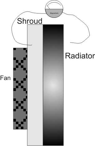
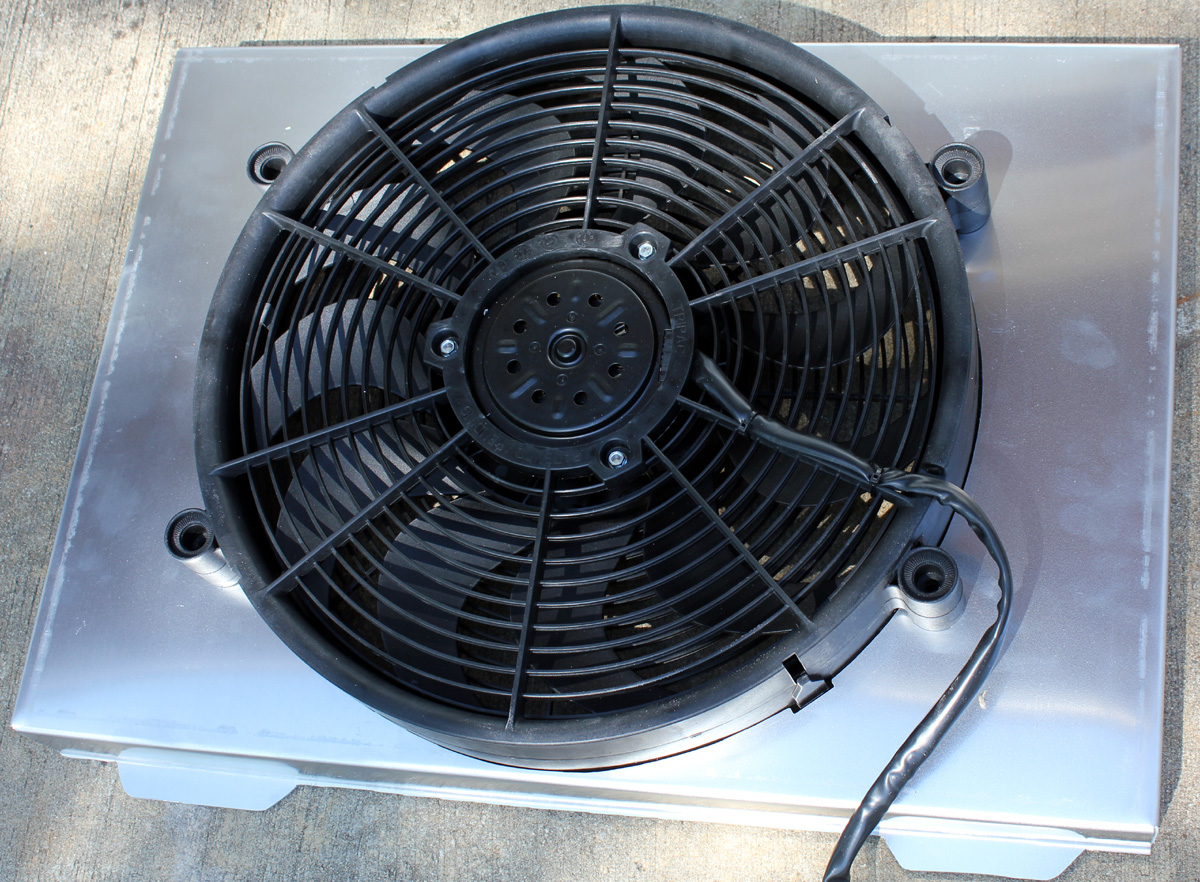
This is my home made fan shroud.
An ideal shroud would cover all of the radiator fin area, forcing air through all of the cooling fins. Additionally, the fan shroud should be as deep as possible. A deep shroud, especially deeper away from the outer edges, makes pressure more uniform across the surface of the radiator. To limit having to weld pieces together, I made my fan shroud as deep as possible just with box and pan brake bending.
My deep shroud, because of limited water pump clearance, required an inset fan. The inset moves the fan away from the water pump. This was an unfortunate compromise over ideal.
Pump
For physical reasons, I elected to use an electric water pump. I used the Meziere 300 series electric water pumps WP311S. This pump supposedly flows 55 GPM.
Pump and Fan
Controller link
Target Temperature
I chose 160-170F as a
target engine temperature. This is because I drive limited street miles, and I
want ~160F at the starting line in a race. I prefer a stable repeatable
temperature that keeps my engine well below boiling at the end of a hard high
horsepower run.
For a long term street car, closer to 200F is more ideal.
This is because emissions are reduced, less moisture collects in the crankcase,
and cylinder bore more fully expands. The engine may produce less power, but the
engine oil collects less moisture and the cylinder bores wear less.
Sensors and Sample Points
While
we can get away with less than idea sensor locations, each sensor has an ideal
location.
Water Pump Velocity
The
ideal sample point for pump speed is at the thermostat housing. This makes
sense, because that is where the thermostat is normally located. It does no good
to use a restrictor or thermostat when using electronic pump control. The
thermostat housing should be left open.
When well below target engine
temperature, my water pump turns at slow speed. This lazily pumps water through
the engine and radiator. The slow circulation promotes even block and head
warming and allows the temperature sensor to get an accurate engine water
temperature sample.
As the outlet water temperature approaches engine
water target temperature, my pump controller speeds up. Just over target
temperature, the pump runs full speed. There is some system hysteresis
caused by the ~10 degree slow to fast pump speed range. The engine tends to
hover very stable right in that range, with the pump just pumping enough water
to keep it there.
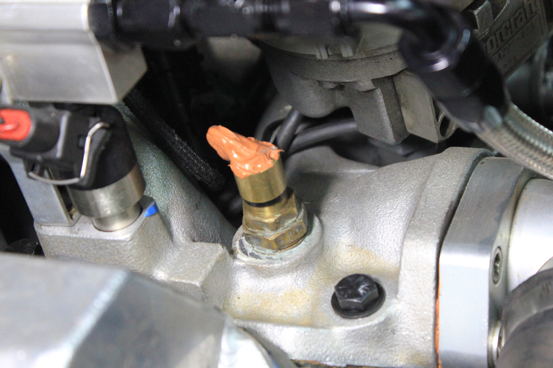
My water pump sensor is located here. The RTV is
just to prevent wire fatigue from constant vibration flexing:
Air Velocity or Fan Speed
The ideal place to sample fan speed is the cold tank of the radiator, or the
radiator outlet hose. The water in the cold tank must always be at least 20-30F
below engine target. If the water is too warm, the pump will run unnecessarily
fast in order to keep the engine at target or worse might not be able to
maintain target. The engine might even overheat if the cold tank is too hot.
If the cold tank is too cold, the engine might stay too cold. This will slow
the pump, and the water might move so slow the engine heats unevenly.
In
my system the ideal cold tank temperature turned out to be about 20F below
target on the street, and 30-40F below target at the track. I compromised my
settings to stay around 30F below target.
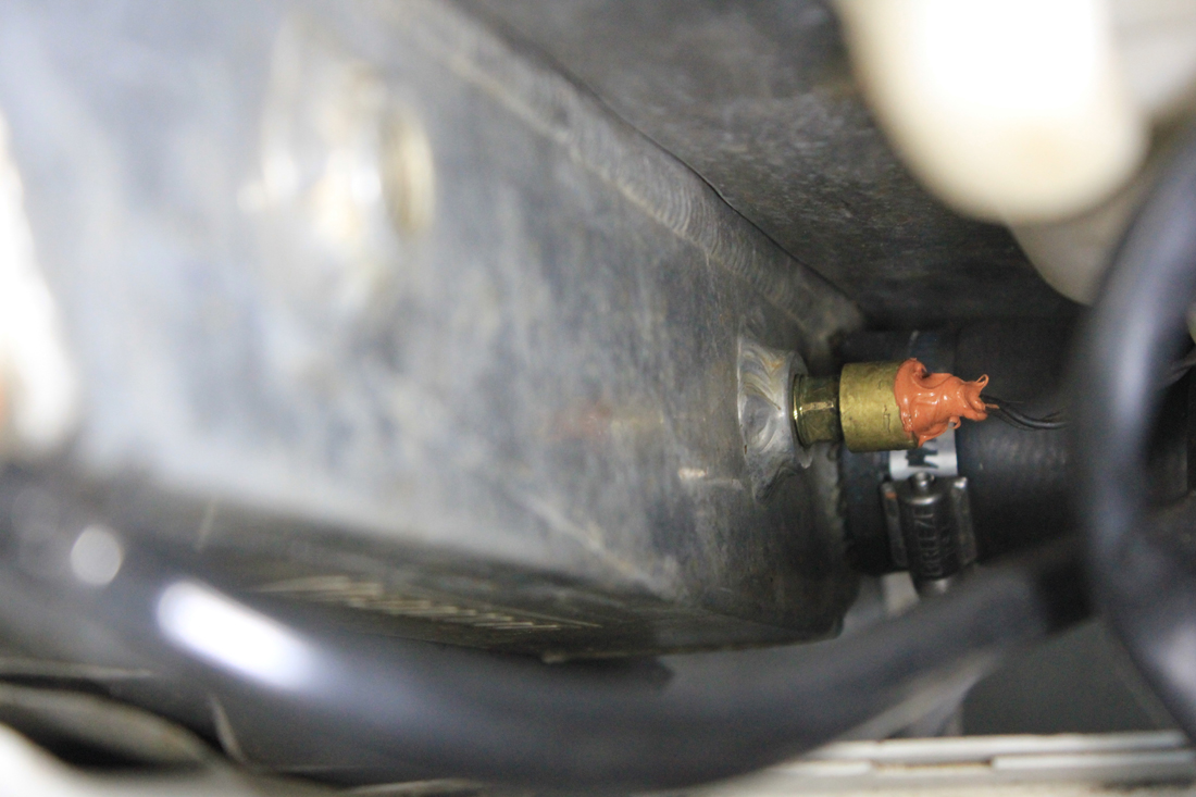
I sample my cold tank water in
the cold tank itself with a thermistor installed in the unused transmission
cooler bung. My electric fan runs full on at 140F cold tank.
If I sampled at the radiator inlet, or worse at the thermostat, my fan would run
too long and too often. I would risk uneven engine heating, and the system would
waste significant battery/alternator power.
Cold tank sensor. Again the RTV is only to reduce chances of damage from
wire vibration.
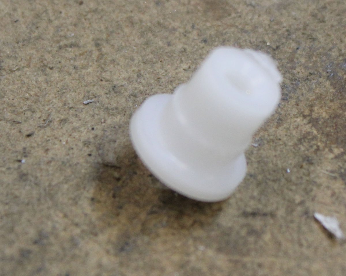
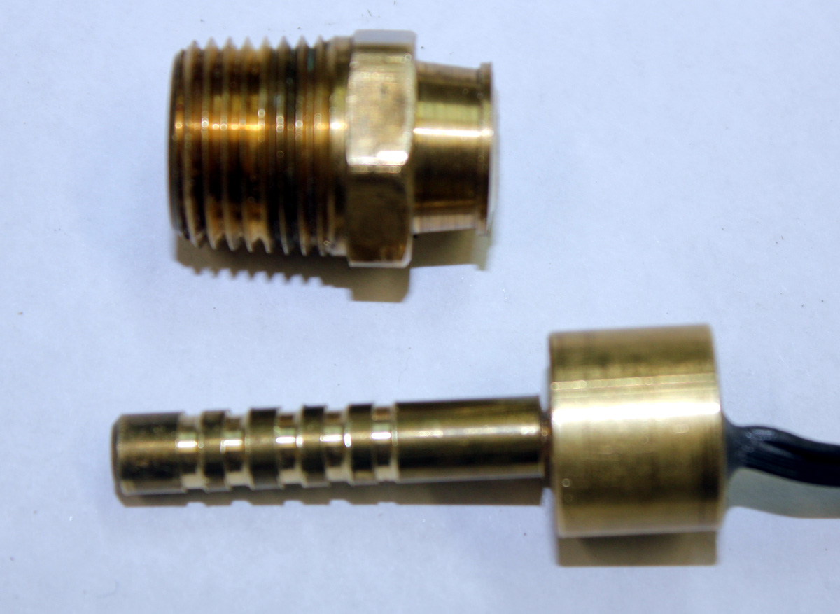
Water sensor adapter
Brass rod. This was barbed
(angle cut) to lock into Teflon insert and to improve water seal
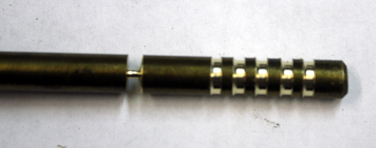
Rod was pressed interference fit into Teflon plug
Assembly before pressing Teflon plug and sensor into fitting
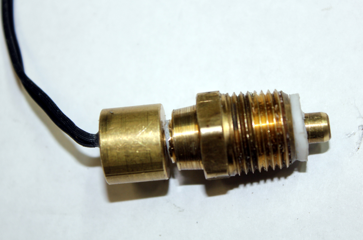
Finished sensor adaptor assembly without
sensor attached

Final assembly with sensor
I
End of text for now.