
I'm in the long process of cleaning this up. PLEASE, if you see something
wrong let me know by typing in my e-mail address
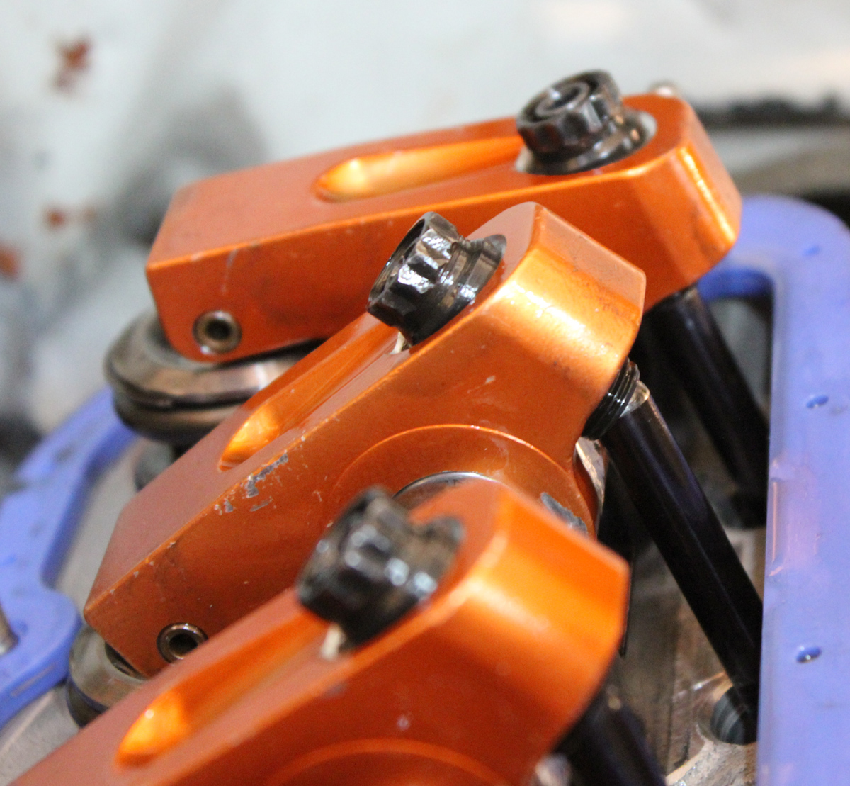
While this article deals with shaft rockers, stud mount rockers function exactly the same way. The rocker fulcrum height sets the geometry in both. The difference is:
I started this analysis because of conflicting information. Some people told
me only pattern centering mattered, others said pattern width mattered most as
long as the contact patch was near center.
My conclusions are narrow patterns are important, but those narrow patterns
should also be close to the "fattest area" of contact. A centered pattern can be
a mile off for geometry or it can be right on. A narrow pattern always means the
geometry is near optimum, even if lateral placement between pushrod side and
exhaust port face is incorrect.
A narrow sweep pattern ensures three things:
The pattern should be centered or reasonably centered, but sweep should also
be narrow. At this moment of time my conclusion is we want pattern no
wider than about 9-12% of valve lift for normal length push rod motor rockers. Longer
rockers would have a lower percentage sweep and be better for high lift high
rate cams, but builders are limited by the length heads require.
Traditional push rod engine rocker arms are very simple first order levers,
like a teeter-totter.
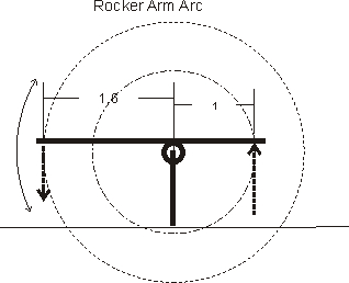
Rocker arm ends move in circular arcs. Thinking of rockers like spokes of a
wheel can be helpful, the axle being the rocker shaft or fulcrum point.
Because of the sweeping motion caused by the "wheel" radius, narrowest possible sweep occurs when the rocker pushes down at right angles (90-degrees) to the valve near half lift. This height, where the rocker is pushing straight down on the valve at half lift, is also the point where the rocker tip is furthest out on the valve from the shaft at half lift. The right angle point is the most outward point of the rocker's circular arc when opening the valve. This is NOT necessarily the optimum point for least wear or pressure over the entire sweep, the right angle point where minimum sweep width occurs is simply optimum at one point of valve lift. Above and below that point the angle is no longer 90-degrees, but that isn't much of a worry because pressure changes slowly around that point.
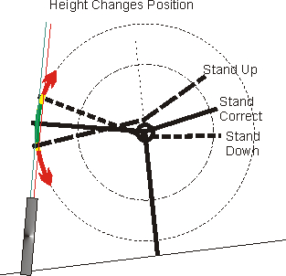
Minimum sweep height results in a pattern that is furthest out on the valve at half lift. We can generally compromise centering and sweep width by adjusting fulcrum point height. In shaft rockers we mill or shim the stands and then get pushrods that match adjuster range. With stud mounts, pushrod length sets fulcrum height. In both system valve tip height compared to rocker pad height height plays an important role.
It is possible to move the rocker tip inward toward the
shaft or fulcrum either by raising
or by lowering the rocker shaft height from the minimum sweep height. We have to be careful, rocker sweep can center
(optimum position) while moving away from the best
angles (optimum geometry). Being somewhat far from ideal doesn't always make this a meaningful or
catastrophic problem. You'll see below how even a 0.2" error has minor
effect on lift, but a more noticeable effect on rocker tip wear and cam timing.
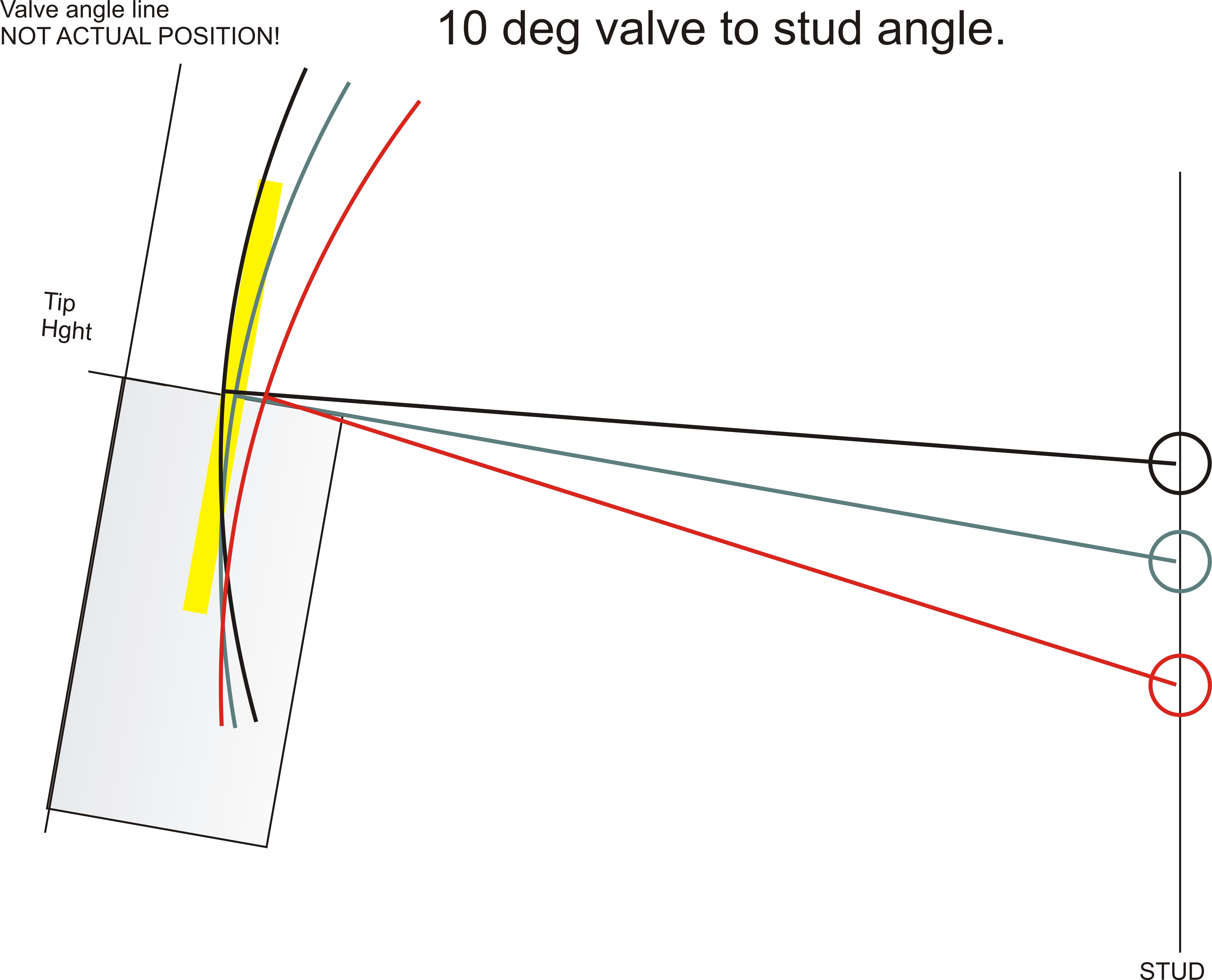
A change in rocker shaft height, in addition to the tip contact centering
changes caused by any valve-to-rocker pad angle (~10 degrees in the TFS-3 heads
I measured), also causes the rocker to angle either up or
angle down. Any angle increase from right angles also moves the valve tip closer to the shaft.
It shortens the "reach" of the rocker tip.
Any rocker geometry error from ideal comes with some mechanical penalties.
Penalties are
negligible even with some pretty large compromises from ideal angles, but
problems increase rapidly as angle increases. When the sweep starts to become
more than 12-15% of lift, with common lifts and
rocker lengths, the system will be edging into noticeable performance loss
and wear increase.
Ideally, when we push anything, we want to push directly in the direction of
movement. We don't push sideways on a car to push it forward, we should not have
rockers push out-of-line on valves or pushrods.
Valve sweep is an arc, technically called a
circular arc. Geometry can only be perfect at one point of the lift
range. Perfect angle, where tip pin centerline and roller contact point to tip
pin is right angles to a line drawn between rocker shaft center and roller pin
center, can only occur at one point in lift. Also, shaft height might need to be
compromised to move the roller tip contact patch closer to valve center. This
means "perfect" is a loose term.
The worse geometry is with shaft heights above ideal.
The best overall geometry is with shaft centerline height lower than the height where the shaft centerline and valve
tip roller pin are level at half lift, and the valve contact with the roller is
90-degrees from a line drawn between shaft centerline and roller tip pin. The
roller wheel radius from the pin affects optimum shaft centerline height. The
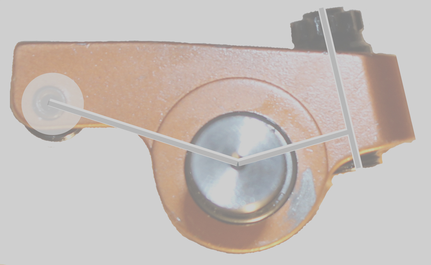
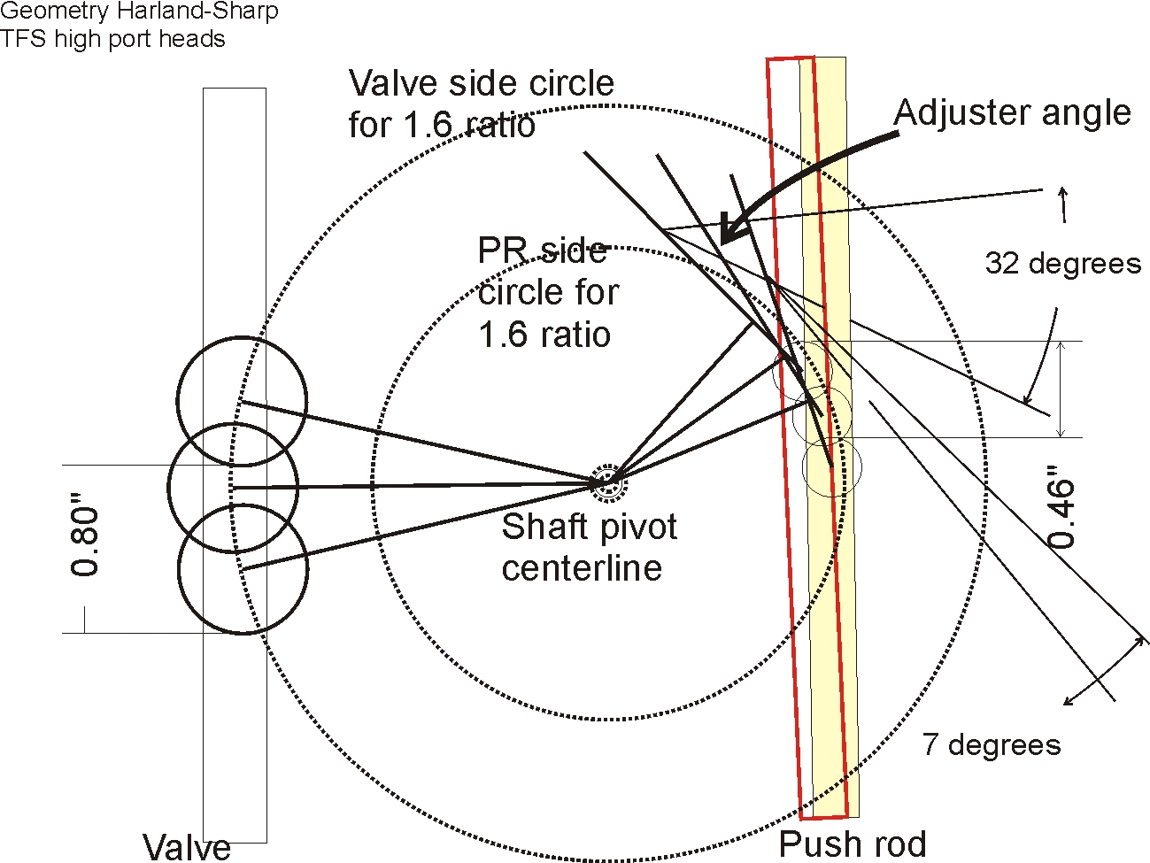
drawing below illustrates the ideal angle at
half lift for minimum sweep. Notice the pin pushes down on the valve
through the roller. The roller is a pivoting vertical spacer. The low friction
rolling reduces the side loads that would be caused by the rocker
tip horizontal sweep. The ideal place to push on the valve is at the valve tip center,
and the roller keeps that pushing force exactly vertical on the valve no matter where
the roller sits. The vertical force on the valve tip, however, will generate
some lateral force on the stem and guides if the roller is not exactly on valve
center. That force would be related to valve stem length to the guide's
supporting area and the distance off center, and it is a very small side force.
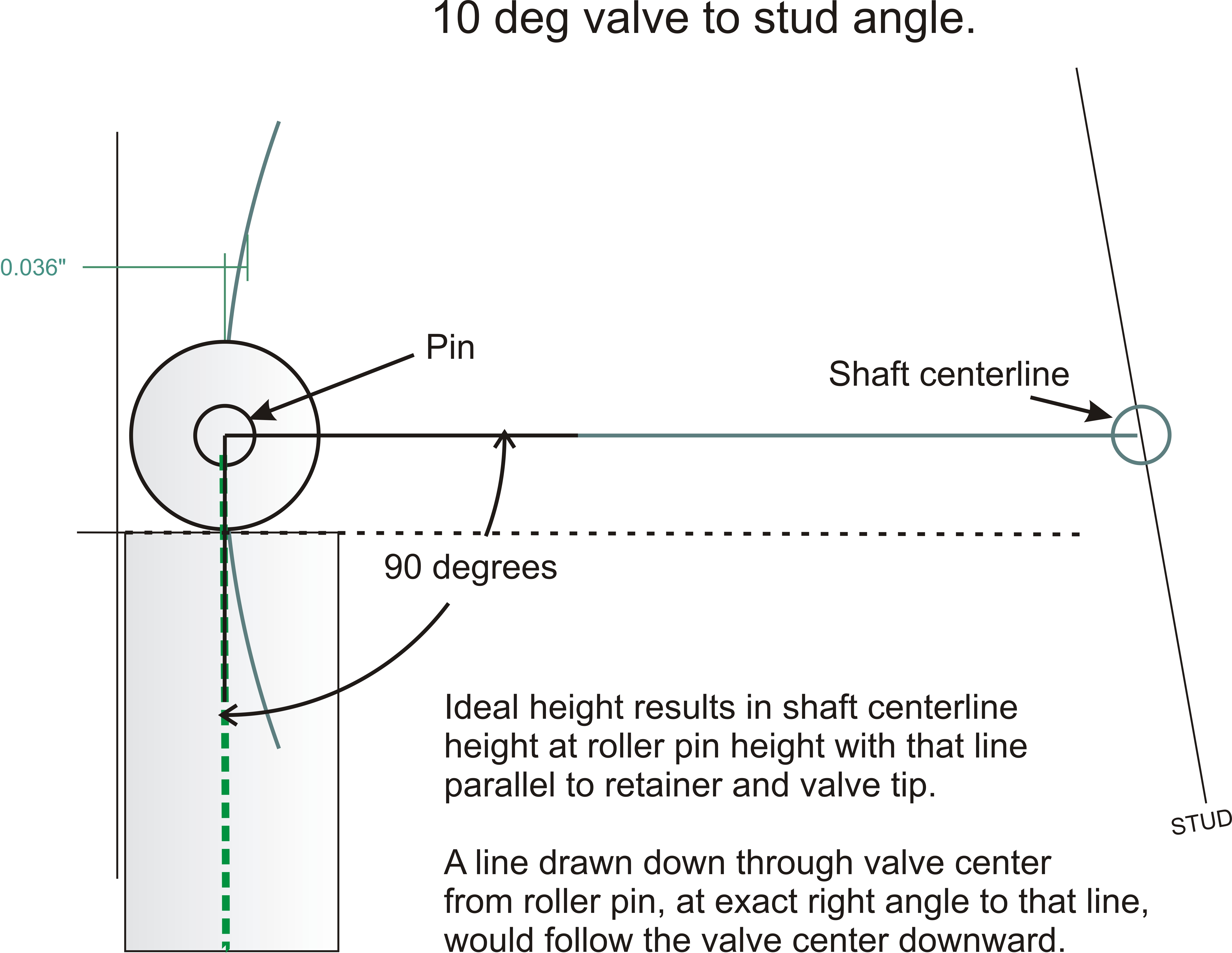
In my TFS-3 heads, the rocker pad surface (where stands or rocker studs
fasten) is
at 80-degrees when the valve stem centerline is the 90-degree vertical
reference. This puts the valve stem and rocker stand at a
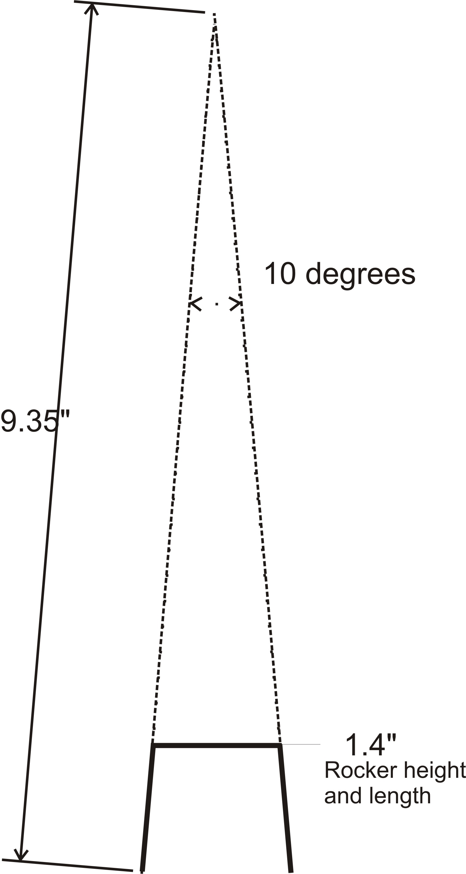
10-degree converging angle. For every 0.1 inch shaft or fulcrum height increase, the valve and
shaft move 0.1 * 10sin = .0174 inches closer together. The valve and a rocker
stud would actually touch about 10 inches above the TFS-3 high port Ford head.
This drawing shows how height alone can change spacing. This is one of two
reasons why raising or lowering the shaft height changes tip contact location:
One way to lower effective shaft height without milling is adding lash caps to
the valves. This makes the valves taller, but the converging angle between valve
and shaft stand from the rocker pad will move the rocker tip out with lash caps.
We all know pushing straight down on something is the most efficient and stable way to move
something
vertically.
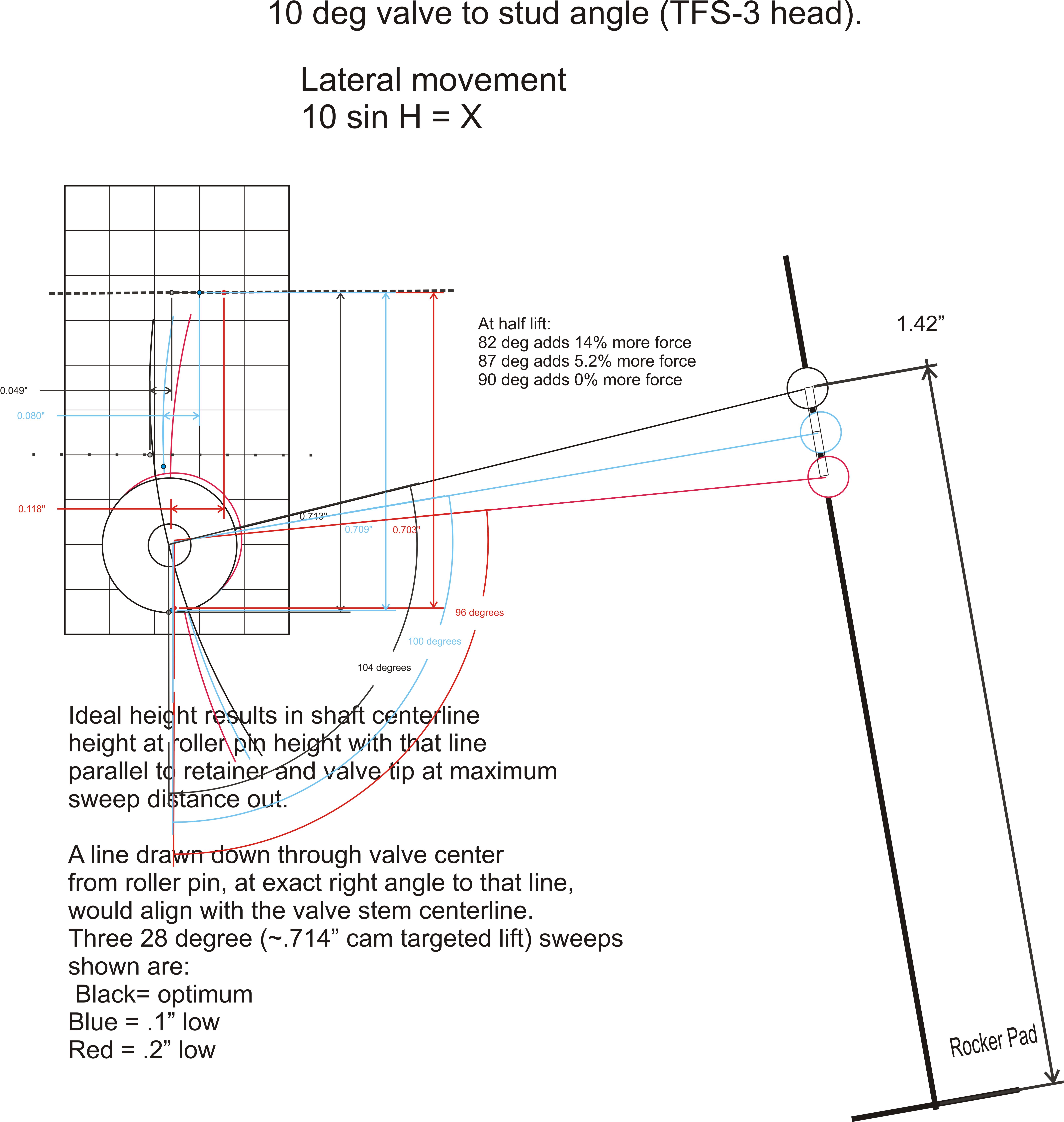
Keeping force angles close to 90-degrees, especially at maximum valve
acceleration lift points,
minimizes wear on the roller tip, maximizes lift, and reduces unwanted deflection.
Temporarily install one cylinder's rocker assembly to manufacturer's guidelines
for your system:
Stud mount rockers are adjusted for travel by changing pushrod length. All of the above guidelines apply, except the only easy user adjustment is through use of lash caps and pushrod length.
Here are plots of sweeps and lift for a 28 degree rocker tip sweep. A 28 degree sweep is roughly around .700 valve lift with the rockers in a small block Ford.
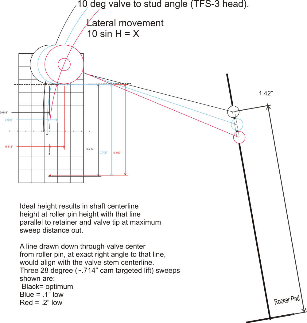
Full lift point including angles
Rocker arms are actually nothing but center pivot levers. They share the same physical
behavior as other fulcrum type levers, including playground teeter-totters and
pry bars.
The length ratios from where forces are applied on both sides of the
fulcrum point determine the ratio of distance movement and ratio of pressures. Like many
other things, the force comes down to a constant inch-pound ratio. If we alter
the lever ratios to increase movement distance (or "inches"), we decrease the
available force ("pounds") on that side. The opposite is also true.
Let's assume we have a simple lever:
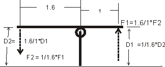
The simple drawing above assumes near zero distance movement compared to lever length. As the lever moves up and down, each end swings in an arc. If we moved the end far enough, it would actually rotate in a circle.
We see the basic functions of a lever above. We trade distance for force by the ratio of side lengths. The 1.6 length side moves the furthest, but has the least pressure. The 1 side moves the least, but has the most pressure. It doesn't matter what the units are, only ratio between the two lengths matter. Let's say the 1.6 is 2" and the 1 is 1.25". We still have 2/1.25 = 1.6 or 1.6 to 1 for the ratio. The sides can be any length or angle that works to align things so long as they are in the proper length ratios from contact point to the fulcrum.
At minimum,. the rocker shaft has the sum of tip pressure plus pushrod pressure. If the spring is 400 pounds and the ratio 1.6:1 (ignoring inertial and friction) the pushrod has 1.6*400 = 640lbs. The fulcrum or shaft has 640 + 400 = 1040 lbs. pulling it out of the head with perfect geometry. Of course friction and inertia add to this, inertial forces determined by acceleration of the masses in the system at both ends, with the largest effect from weight at the valve. Mass has the least effect in the area of the rocker shaft.
These forces are increased by geometry errors.
With a central pivot or support the length ratio between the two sides, where they are being pushed on or pulled on:
1.) The ratio determines the ratio of distance each side travels.
The longer side moves further in proportion to the rocker ratio. The travel
distances are
in proportion to rocker ratio if contact motion is 90-degrees to the effective arm angle
on each side
2.) The ratio determines the pressure or force. The shorter side has the most force in
close proportion to the ratio if the force is applied 90-degrees to the
effective lever angle.
3.) Minimum wear and stress and maximum motion occurs when things are either at 90-degree angles or straight, but we can't always do that perfectly.
From this we can conclude if we use a properly constructed and installed 1.6 rocker arm, the maximum possible distance the valve can move is 1.6 times cam lift. The force on the cam and push rod is always more than 1.6 times the force required to move the valve, and that force is minimum when the push rod is at a 90-degree angle to the short side line. For best valve control and minimum wear and tear the push rod and valve should be 90-degrees from the effective lever angle on their respective sides of the fulcrum.
Rocker ends move in a circular arc. Any point on either end swings through a small portion of a circle, that circle being centered on the rocker's pivot point. The pivot point does not have to be what we physically see as the center of the body. The pivot point is the center of the shaft in any rocker with a shaft, either stud or shaft style rockers. On a cup type pivot, the pivot point is the center of circular arc of the pivot.
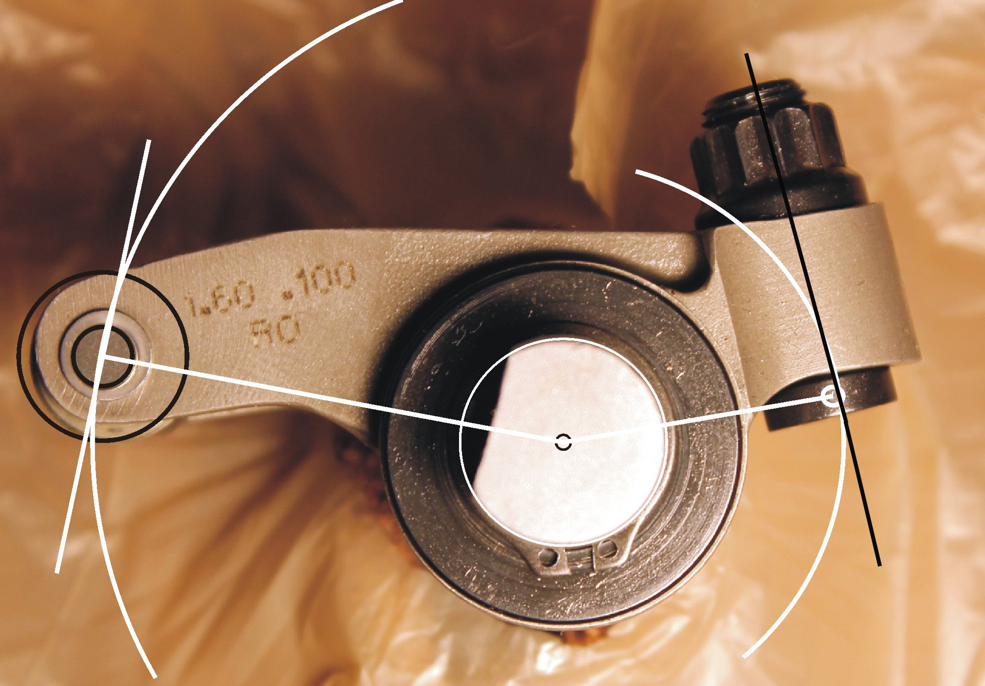
The straight white line at the roller tip is the 90-degree alignment angle where forces in the entire system are minimum. The straight black line is the angle where wear and bending force on the push rod is minimum. The lines would respectively each be aligned with the valve and pushrod at half lift.
If
we draw two circles, one with the radius of the valve tip contact point and
the other with the push rod contact point centered on the fulcrum point, the radius
(or diameter) ratios would be the true rocker arm ratio. We see this as:
We can see the rocker arm tips and contact points have to follow each circle's radius, and how this forms an arc. The center of the circle is the same point as the center of the shaft in a shaft or needle bearing center stud mount rocker system. The circle's centers are ABOVE the pivot point in a standard OEM cup pivot stamped arm.
Changing the height relationship between the fulcrum and valve tip changes the position of the contact and the width of the
pattern on the valve tip. The ideal pattern sweeps
outward from minimum lift, reaches peak outward distance at half lift, pulling
back in toward the pushrod and fulcrum at both maximum and minimum lift. The
ideal pattern centers on the valve tip.
If acceptable pattern width is not found with
proper centering on the valve, the pivot point has to be moved laterally toward
or away from the valve while maintaining ideal pattern. Lowering or
raising the pivot or shaft height to center the pattern is only correct if the
pattern width is acceptable.
Raising or lowering the stand away from narrowest sweep always
moves the pattern toward the pivot point, but it also decreases lift and
duration, and increases wear. Improper geometry harms valve control, requiring
higher spring pressures or lighter weight components to achieve the same RPM
before loss of valve control or valve float.
Maximum safe RPM for given weights and springs and minimum wear occurs in the
green area of sweep. This is also the narrowest sweep
The goals when setting rocker arm geometry are maximum possible lift with
minimum stress and wear. This is accomplished when the vertical sides of the
imaginary circles are aligned with respect to push rod angle and valve stem
angle. A 90-degree angle to a line drawn between valve contact point and pivot
centerline is ideal at the valve. A 90-degree angle is also ideal at the push
rod end.
Since valves stems and push rods are not parallel, this creates a conflict
A straight-across line obviously cannot produce optimal angles at both ends with valves and push rods on converging angles.
These angle might be ten's of degrees.
TFS high port heads, for example, have 20 degree angle valves to the lower deck
surface. The rocker stud holes are at 10 degrees referenced to the same surface.
The push rods are at similar angles, depending on cam location and deck height
of the head in relation to the camshaft centerline. Taller deck motors are more
forgiving of push rod angles, all other things equal.
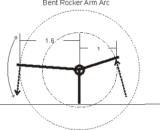
These angles result in the inability to push a perfectly flat rocker at right
angles at both ends. The solution
is simple, the lever is simply "bent" at the fulcrum. The angle alignment is
built into the rocker's physical design and construction.
A properly designed rocker, through proper internal angles between each end's
contact point and the central fulcrum, allows both the push rod and the valve to meet the rocker at very close to right
angles. Right angles produce optimum lift at the same time they provide minimum stress and wear.
Note the following for ideal geometry, although obtaining ideal is often impossible:
The best overall geometry compromise is to adjust center pivot height for
minimum valve tip sweep. Centering the sweep requires lateral movement of the
pivot point, either toward the push rod or toward the valve. Sweep misalignment
to valve center should not exceed ~15% of valve tip diameter either direction.
For a .341" diameter valve, sweep patterns going beyond .051" from center either
direction will result in rapidly increased side load on the valve. Sweep widths
over ~15% of stem diameter should also be avoided, with the least possible sweep
resulting in the least wear and maximum lift. This will keep the rocker tip in
the wide area of the valve with minimal back and forth scrubbing or stem
rocking.
Most rocker systems provide height adjustments that can be used to minimize sweep width. Unfortunately they lack the lateral pivot or stand movement in a line with the push rod and valve necessary to center sweep pattern on the valve.
Pivot height can be compromised, using the converging angle between center
support and valve, to move the tip in or out. Maximum out always occurs
near optimum sweep, and any height change above or below optimum will pull the
pattern toward the push rod. Unfortunately this also results in a wider sweep.
If the sweep cannot be kept below ~15% of stem tip diameter and never go more
than ~15% off center, the risk of premature wear increases.
This is likely why we hear advice that the sweep should be under .050" or .060"
total sweep, and that the middle of the sweep pattern should be centered on or
very near valve center. This is sage advice, based on valve physics.
Proper geometry is highly dependent on the rocker arm system itself and how
it was manufactured. The only practical field adjustments (outside of
re-machining something major) are push rod length, fulcrum height, and valve
height above fulcrum. In common small block Ford wedge heads the valves, the rocker
fulcrum or stud holes, and the push rods are on converging angles like this:
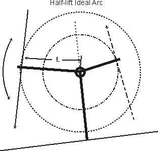
If the valves or fulcrums are too high for "L" (the pivot centerline to rocker
tip centerline distance) the rocker system cannot be corrected without
machining. Be very careful before making changes that cannot be undone!
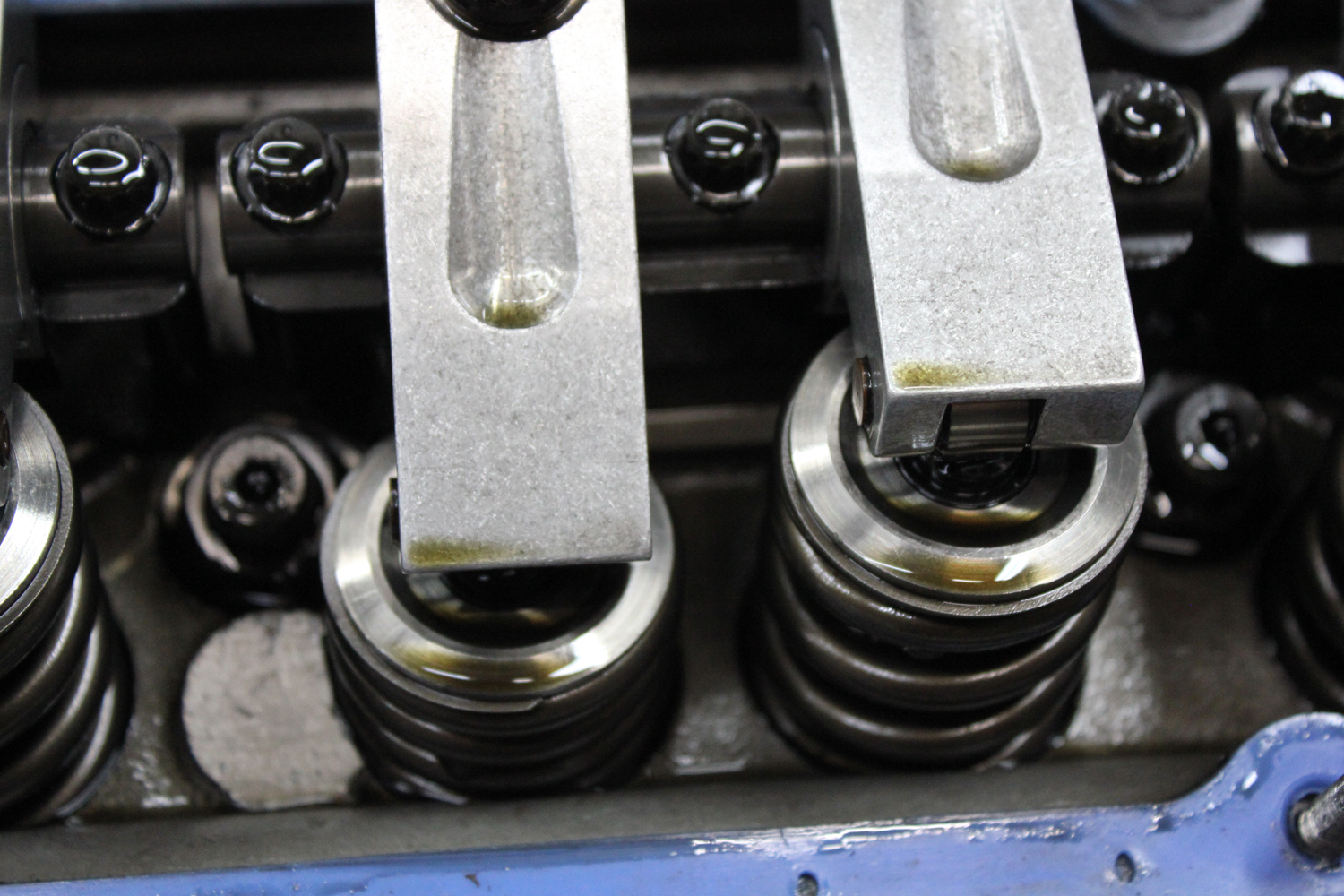
The very first step is always to look at valve to rocker pattern width.
As the valve length above head is made longer (such as lash caps) and proper
pattern maintained, the rocker tip patterns move toward the exhaust ports.
These are rough angles taken from photos of TFS Highport heads. These angles
are from two different camera shots. They are subject to various errors and
should not be considered completely accurate, even though they do agree within a
degree or two :
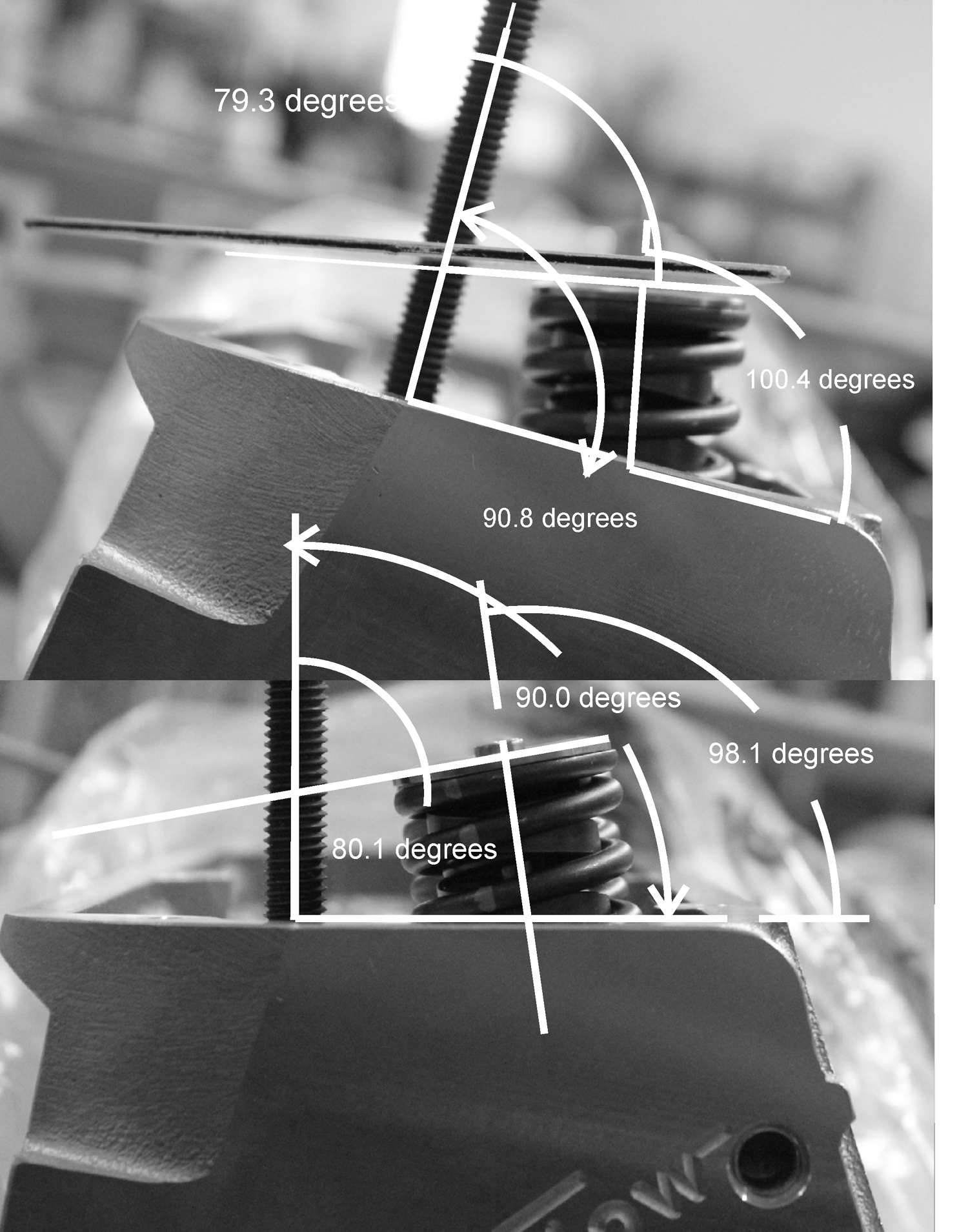
The 10 degree angle difference between the stud shelf or
80-degree to the "rocker pad" surface results in a tip movement the cosine of
the angle times the height change. For 10-degrees found in the Highport head we
have 10sin * .1 = 0.017365" outward movement on the valve for every .1
inch fulcrum and valve height increase. Changing stand height +.15 inches moves
the tip out approximately .15 * 10sin = .026 inches. Conversely lowering it
moves the pattern toward the fulcrum the same amount .
We can see how raising or lowering the shaft centerline can be used to center
contact pattern on the valve tip, but we do not want the angle at the tip to
deviate far from 90-degrees at half lift. One way we can tell if we are off is
if the pattern only sweeps one direction through rising lift, or if the pattern
gets wide. If the roller tip moves outward with increasing lift, the shaft is
lower than ideal. If the roller tip sweeps inward toward the shaft with
increasing lift, the shaft is too high.
Perfect shaft height would be when the contact starts in, sweeps out reaching
maximum out at half lift, and then sweeps back in as lift goes toward maximum.
You can see why in the drawings below. We also want the swept pattern to center
on the valve tip.
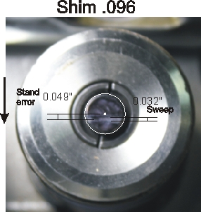
I plotted my TFS heads graphically using CoralDRAW. With my ~.680 lift
cam and 1.6 ratio rocker arms, the narrowest possible sweep when the rocker
fulcrum and valve tip at half lift are at the same height was about .028 inches.
The theoretical minimum possible sweep is .028" at that lift, and I was able to
obtain 0.029" in practice. This tells me my measurements and angles are
likely very close.
I also plotted a theoretical sweep of .115" at the settings as delivered, with
the shafts .192" below optimum. This plot assumes still having .680 valve
lift, which would decrease slightly with the angle error.
This is incorrect sweep width:
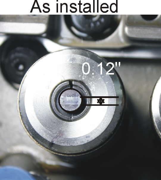
Note the pattern is centered. It also crosses valve center at half lift. The
problem is the pattern is far too wide.
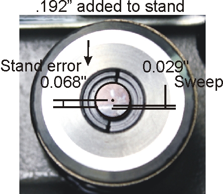
Note the pattern above is acceptable with
slightly less shim. The sweep is narrower than required, but centers too far
outward away from the fulcrum.
Less shim would move it in (because it rotates up on the tip circle) but would
also make the pattern wider.
Below is the optimum pattern width shim, which would have been a .152 shim over
stock height. This is about .015-.020" tighter than theoretical for the .680
lift cam, which indicates measurement error. I suspect this is from flexing in
the stack of washers I used to shim the stand. That was a pretty tall stack of
washers with several hundred pounds of open valve spring pressure.
Unfortunately this pattern is out grossly too far
on the valve. The only correction would be to shift the shaft inward toward the
intake about .068 while re-shimming to keep sweep at minimum.
The above pattern could be corrected with a .170 or so shorter valve tip height off the head surface and less shim, instead of moving the stand laterally ~.068" toward the intake and keeping optimum height stand shims. This would be the most accurate, least stressful, and by far the highest lift and lowest wear pattern if centered.
Patterns should never be centered by changing shaft height without considering any effects on pattern width, nor should they be made narrowest without consideration of centering. A wide pattern will wear parts (including the valve guides) prematurely and can also reduce lift, while a narrow but offset pattern can also increase wear on valve guides (although less than a wide pattern). The ideal pattern would be the narrowest possible pattern at or very close to valve center.
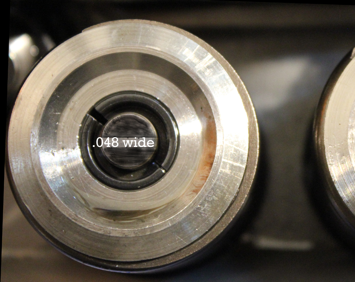
Another engine had problems spooling. It also damaged push rod ends every few
passes.
The rocker pattern was acceptable with a .048 pattern but was just barely
kissing the retainer. Adding the thinnest lash caps available made the sweep
slightly narrower and corrected the retainer contact, but the engine continued
to wear out pushrods.
The acceptable pattern without lash caps looked like this:
The push rods looked like this:
The push rods had too much angle and were blocking the oil hole. As a matter of
fact, they were almost going out of cup.
Stand shimming made this problem worse and destroyed the valve pattern. A longer
pushrod improved angles, as would another 1/2 inch of valve end height with a
shorter pushrod, but neither was workable. The problem was adjuster angle.
Harland-Sharp was nice enough to sell me corrected rocker arms. They re-angled
the adjusters and the problem went away. The engine picked up ET and MPH and
also spooled faster. The valves had more lift with corrected rockers, and the
valve sweep was still good.
The original rocker diagramed out like this. This is where the adjuster would
have had to be to work. It would have put the pushrod in the rocker body and not
oiled, plus the pushrod would have hit the rocker body. The diagram
helped me see the problem.
Changing the adjuster from 71 degrees to 87 degrees, a 16 degree change, would correct the pushrod angle.
WARNING: This data is unverified and has not
been peer reviewed, but I believe it to be accurate
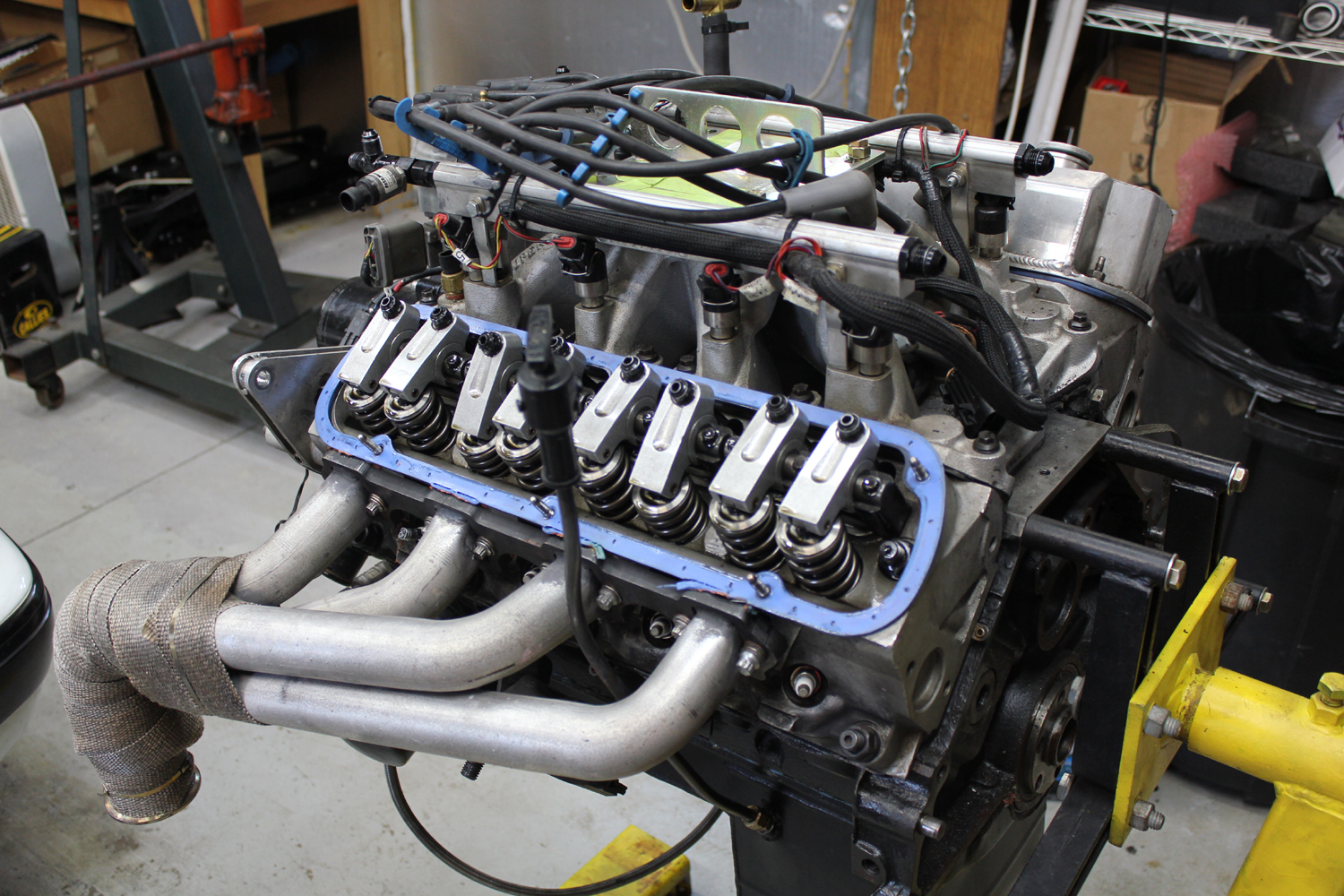
My crankshaft, rods, pistons, and block are very good parts. I like to
overbuild components that can completely destroy an engine. My engines all have
Bryant billet or Callies 4340 forged crankshafts. The rotating assembles likely have an
upper RPM limit well into the 9000 RPM range. This means the valve train
and camshafts generally determine the safe RPM range.
I received conflicting advice on RPM limits of latest engine's valvetrain. The engine builder
insisted on titanium intake valves to safely spin 8K RPM, while TFS/TEA claimed
out-of-box 225 high ports with stock 240 lb. roller cam springs were safe to 8000
RPM. I thought I would try to do a spreadsheet to calculate pressures through
the system.
The basic steps I use are:
1.) Use RPM to determine time intervals per degree rotation
2.) Use position to determine time where a certain lift is reached (this gives
lobe profile)
3.) Calculate velocity at various lift points
4.) Calculate acceleration of the component to determine G-forces (inertial
force)
5.) Calculate spring pressure at those points
6.) Add spring pressure to the effective "inertial weight" of the components at
the valve end of rocker, including that portion of the rocker
7.) Calculate cam side G-forces and inertial corrected weights on that rocker
side to get the effective cam side weight
8.) Add spring force appearing at the cam side to the combination of rocker,
pushrod, and lifter weights on the cam side
9.) Apply the remaining spring force to the cam side
If cam side force reaches zero, the lifter will no longer follow the cam.
Similarly if forces at any pressure coupled joint, such as valve to rocker or
pushrod to lifter reach zero or go negative, the joint will come uncoupled.
Known flaws in my spreadsheet at this time are:
1.) Effective weights of things that do not move at a constant velocity over the
weight, such as valve springs or rockers, are estimated. For example the spring
bottom does not move while the top does, the middle moves about half the
distance as the top, so I corrected the spring static weight to 65% of
full weight.
2.) Oscillations and vibrations are unknown. I do not know the mechanical "Q" of
the spring nor do I consider resonances.
3.) I have very coarse lift data, I only took degree data every .025" at the cam
I've reached the following conclusions:
1.) Trickflow / TEA was correct. The stock springs, at least with my cam, would
be safe to 8000 RPM **if set at 240lbs seat**. Unfortunately my heads were set
at 200 lbs, making float around 7500 RPM. This seemed to be true in operation.
2.) The valves are already so light compared to other weights they should be a
last resort, not a first. As Trickflow/TEA recommended, a PAC 1226 or 1326
spring set at 280-300 lbs. seat would take the valve train to 8500+ RPM.
3.) The idea of adding 1 pound of spring for 1 pound of boost cannot possibly be
accurate. In my case it looks like any type of spring correction for boost is
meaningless
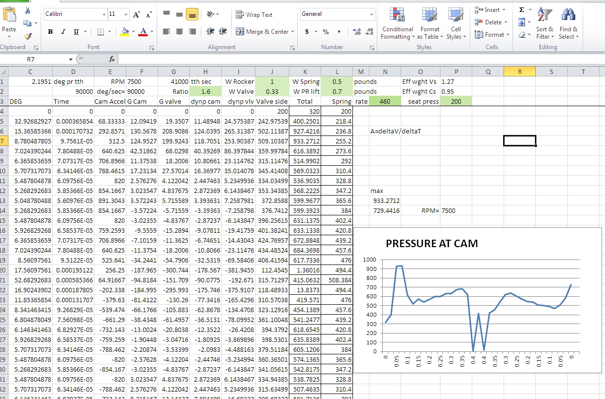
In the spreadsheet below, with my springs set at 200 lbs. seat and with my cam,
the roller pressure on the cam reaches zero at 7500 RPM. Bumping spring pressure
up to 240 makes my system safe to 8100 RPM. This what TrickFlow TEA said,
although the exact RPM depends heavily on the camshaft ramp.
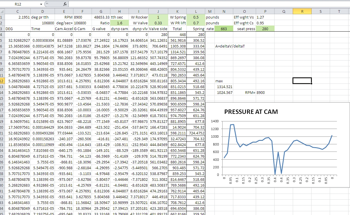
Changing to heavier PAC 1326 springs calculates to allow my present cam and
components get into high 8000 RPM range,
making it safe at 8500 RPM. Once again this agrees with TEA. Keep in mind this does not include
component life considerations. It is only the point of "float" at the valve-to-rocker
junction or lifter to cam contact. This calculation does not allow for spring oscillation, which can
cause valve-to-valve seat or retainer-to-spring bounce. I was just looking for
some way to know whose opinion or advice was closer to the real world.
.
Calculations for PAC 1326 springs
CARS index Top