How a Wastegate Works
Figure
1
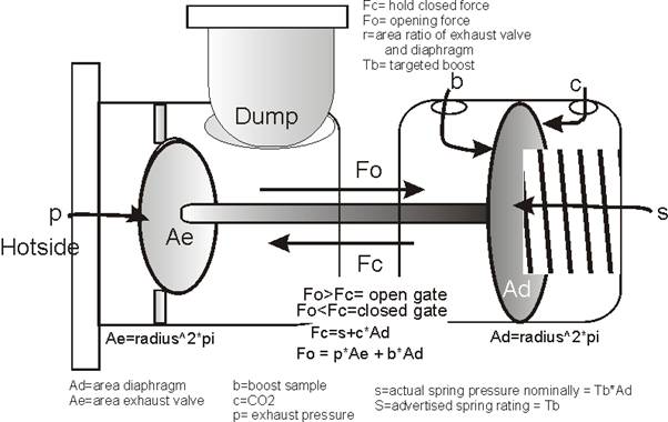
Wastegates have a dome control side that is thermally
isolated but mechanically connected to an exhaust valve side. When (figure 1)
interconnecting shaft Fc (closing force) exceeds shaft Fo (opening force), the
exhaust valve is forced shut against a seat. When Fo (opening force) exceeds Fc
(closing force), the exhaust valve opens. Moving the valve off the seat dumps
exhaust, reducing turbo drive pressure and reducing compressor speed. This
reduces boost (b) pressure on the diaphragm area (Ad) until Fc exceeds Fo and
the valve closes.
We ideally want the valve to remain firmly seated until
target boost (Tb) is reached. Any valve movement or exhaust pressure leakage
through the valve will slow the build of turbo drive pressure. The goal is to
firmly clamp the valve shut until target boost is reached. This requires dome
force dominate the force caused by hotside pressure.
When Tb is reached, an ideal gate would open the valve just
enough to reduce drive pressure until target boost (Tb) is maintained, or to
just oscillate around the opening and closing point. A gate with ideal dampening
would move into equilibrium, hovering partially open and keeping the turbo at
target boost (Tb).
Dome pressures, namely a boost sample pressure trying to
open the valve and dome pressure (from a spring and/or CO2) trying to close it,
should fully control the gate in spite of exhaust pressure trying to force the
exhaust control valve open. Ideally dome working pressures should greatly exceed
the opening force resulting from exhaust pressure acting on the valve surface
area.
There is more to a wastegate than first meets the eye. One
thing commonly missed is the wastegate is also a pneumatic pressure amplifier.
The gate’s pneumatic leverage ratio or “force gain” determines gate control
accuracy, unwanted exhaust pressure leakage, and boost control stability and
repeatability. The wastegate’s pneumatic leverage or “gain” increases gate
immunity to hotside exhaust pressure. This leverage or gain is determined solely
by the ratio of dome diaphragm diameter to exhaust valve diameter. The exact
ratio can be most simply calculated by the ratio of the diameters squared. This
means control and stability rapidly improve as the dome diaphragm size increases
in proportion to the exhaust valve. Twice
as much size ratio is not just two times better; it becomes four times better
for stability and control.
Typical Spring-only Operation
Figure
2
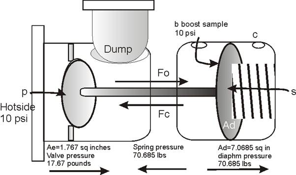
In spring-only operation, sample boost from the compressor
outlet is fed to the opening side of the dome. The diaphragm’s area multiples
boost sample pressure to a final level that acts against the spring. For
example, if the diaphragm is 4” diameter and boost pressure is 10 psi, the boost
sample opening force acting against the spring will be:
Fo =Ad*b where Ad
is diaphragm area. Area is found by A=r^2*pi
If the diaphragm is 3 inches in diameter, diaphragm area in
square inches will be 1.5^2*pi= 7.07 sq in. The pressure in pounds per square
inch acts on that area.
With 10 pounds per square inch boost on the dome reference
pressure side and an open atmosphere dome spring side we have the area of 7.07
square inches times 10 pounds per square inch pressure for a total mechanical
force of 70.7 pounds. 70.7 pounds is the actual linear force acting to push the
gate valve open.
In this example the real spring pressure required for 10
psi boost, assuming zero psi pressure on the exhaust valve, is 7.07 times the
sampled target boost or 70.7 pounds. A “10 pound boost” specification spring
would actually require 70.7 psi of actual spring pressure with 3 inches
diaphragm diameter. The exhaust valve would have 70 pounds pushing it shut
against exhaust average and peak pulse pressure.
We really do not want the valve rattling open and closed,
the best gate would have a large diaphragm to valve ratio. This means we
generally want the largest workable diaphragm area compared to valve area. The
sole exception to this is if we just pin the gate shut or have it fully open
with no intention of letting the wastegate itself regulate or control boost
levels. If a boost sample goes into the gate, especially if it is a bled sample
to increase boost, we need the largest possible dome diaphragm to gate valve
area.
Control Error
Working against that spring force (and any dome CO2) is
exhaust valve pressure. Exhaust valve pressure is the overwhelming contribution
to gate instability and target boost errors. Hotside pressure working against
the valve counteracts dome control forces.
A 15.5 inch exhaust valve has an area of r^2*pi, or
0.75^2*pi = 1.77 square inches. With a hotside gate inlet pressure of 10 psi and
an exhaust valve diameter of 1.5 inches, the gate has 0.75^2*pi *10 = 17.67 lbs
of additional Fo (opening force). This additional Fo contribution, caused by
exhaust pressure pushing against the gate’s exhaust valve area, adds directly to
the opening force (Fo) provided by the boost sample acting on the diaphragm
area. The force created by both the exhaust and the boost sample on their
respective areas sums, the resulting net force tries to open the gate against
the spring and dome closing pressure.
In this example, additional exhaust valve pressure causes a
gate that would otherwise open perfectly at 10 psi (in a static test) with a 10
psi spring (70.7 psi actual pressure) to open prematurely. If, as in this
example, turbine drive pressure or hotside pressure hovered around 10 psi the
gate would open as if the spring were 70.7-17.67 = 53 psi. An exhaust pressure
of 10 psi causes our 10 psi Tb (target boost) spring to release at 53/7.07 = 7.5
psi boost.
Of course hotside pressure decreases with reduced
compressor load or boost, the gate would not open exactly at 7.5 psi if the
hotside pressure changed, but it would be close.
I simplified this ratio effect by assigning a figure of
merit called “control gain”. The control gain of a wastegate works out to be the
ratio of valve and diaphragm diameters squared (E/D)^2 = Cg with D=dome
diaphragm diameter and E=exhaust valve diameter. With the example gate’s exhaust
valve diameter of 1.5 inches and dome diaphragm 3 inches in diameter, we have
(1.5/3) ^2 = control gain of 1/4. From this ¼ of the exhaust valve pressure is
subtracted from the targeted boost, so 10 psi hotside would deduct approximately
2.5 psi from boost. This is a quick way to get a feel for gate sensitivity to
hotside pressure. Closer diameters of the dome diaphragm and exhaust valve
result in less reliable gate control in the presence of hotside pressure.
Dome Control by CO2
CO2 acts as a
countering force to the boost signal. CO2 countering pressure is independent of
dome diaphragm diameter, but opening boost is still dependent on wastegate gain.
Let’s look at an example of a small turbine driving a fairly large compressor
with a turbo drive vs. boost ratio of 2:1. With 20 psi boost we have a drive
pressure of 40 psi. The gate described above would have 1.77*40=70.8 pounds
trying to force the gate open. This adds to the 20 psi of boost sample acting on
the dome diaphragm area of 7.07 square inches at 141.4 pounds for a total
opening force of 212.2 pounds. Real spring pressure plus CO2 pressure on the
diaphragm has to total more than 212.2 pounds or the gate will open. If the gate
opens prematurely target boost will not be reached.
Earlier we concluded CO2 directly subtracted from boost
sample. With 20 psi dome CO2 cancelling boost, and with our 10 psi spring and
zero exhaust pressure, gate opening would occur at 30 psi. There would be 20*Ad
= 20*7.07= 141.4 lbs force from CO2 added to the 70.7 psi spring for a closing
force of 212.1 pounds.
As with the spring alone, hotside pressure acting on valve
area tries to open the valve. With a 2:1 turbo drive ratio 20 psi would have 40
psi working against the valve, for a net force of 20*1.77 = 35.4 lbs of exhaust
valve opening pressure. This makes
net closing force 212.1-35.4 = 176.7 pounds, which is a sample boost pressure of
176.7/7.07 = 24.99 psi. We should have had 20+10 = 30psi boost with a 10lb rated
boost spring and 20lbs of CO2, but we fall 5 psi short.
Lower Gain
Wastegates
Gates with low ratios of diaphragm diameter to exhaust
valve diameter exaggerate boost control issues. As the gate approaches a 1:1
valve to diaphragm ratio, the gate becomes increasingly sensitive to hotside
pressure. Of course none of this matters if you are simply pinning the gate
shut, as long as you have enough CO2 pressure or low enough hotside pressure to
successfully pin the gate.
There is also little if any control speed advantage to a
small dome. While a smaller dome area fills faster for the same CO2 source
pressure, it also requires a lot more pressure.
What is saved in filling time is counteracted by requirements for higher
dome pressure. Exact changes would have to be calculated based on dome area,
line size, source pressure, and target dome pressure.
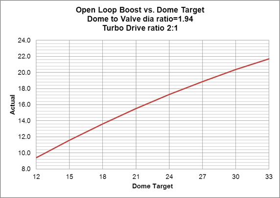
If a vehicle uses ramped boost control, a larger dome
diaphragm clearly offers better boost control in an open loop control system.
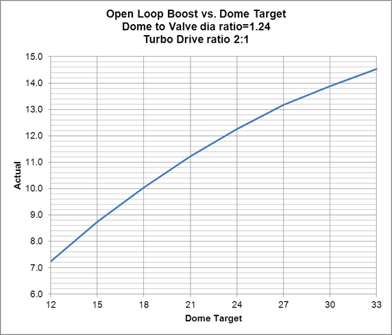
Here is a graphical comparison of two wastegates, one with large
diaphragm to valve diameter ratio and the other with low diaphragm to valve
diameter ratio.
Dome target is the sum of spring target and CO2 pressure.
Actual boost is calculated for a turbo with typical drive to boost ratios
peaking at 2:1 drive pressure ratio at full compressor flow.
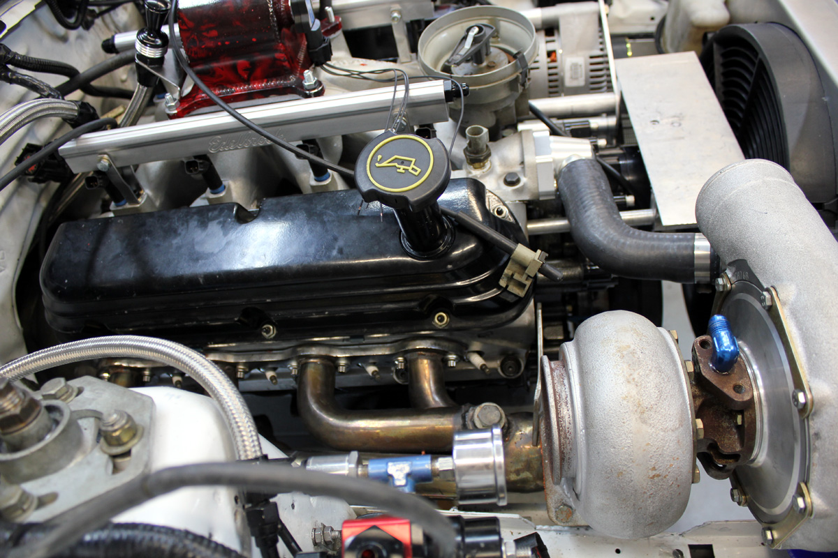
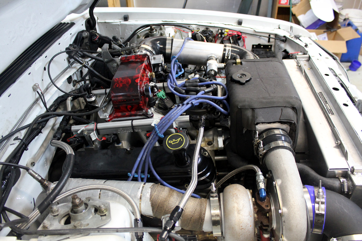
RG-45 Wastegate with T04 flange 76mm Custom Race Turbo
Early Change to Turbo (old stuff)
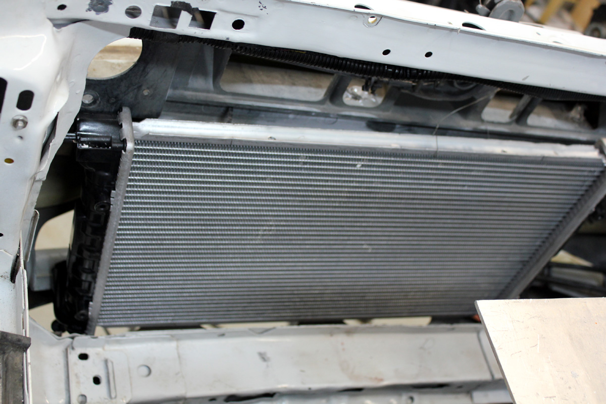
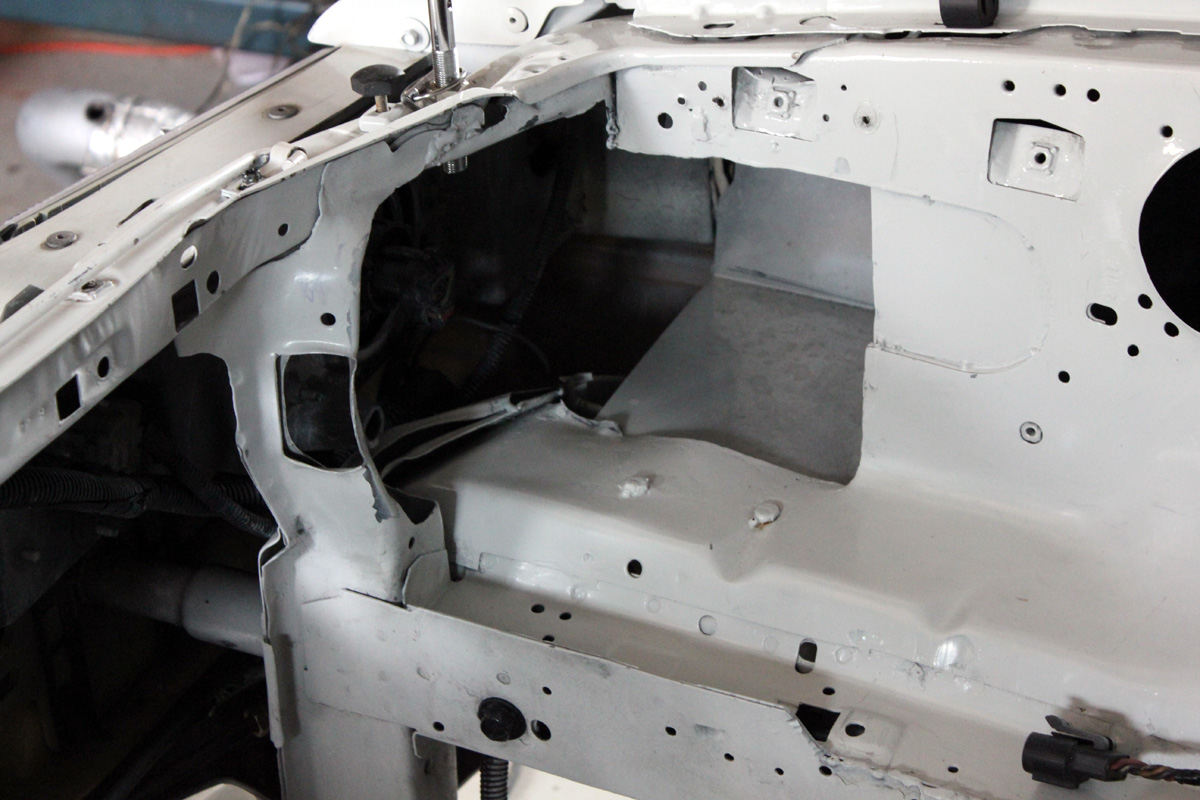
Air inlet area where filter will sit. This is boxed and open only toward the grill.
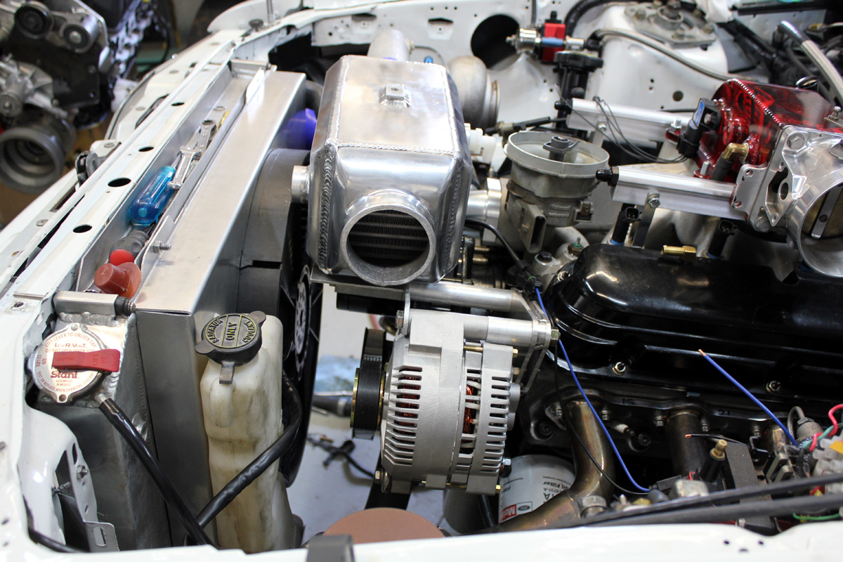
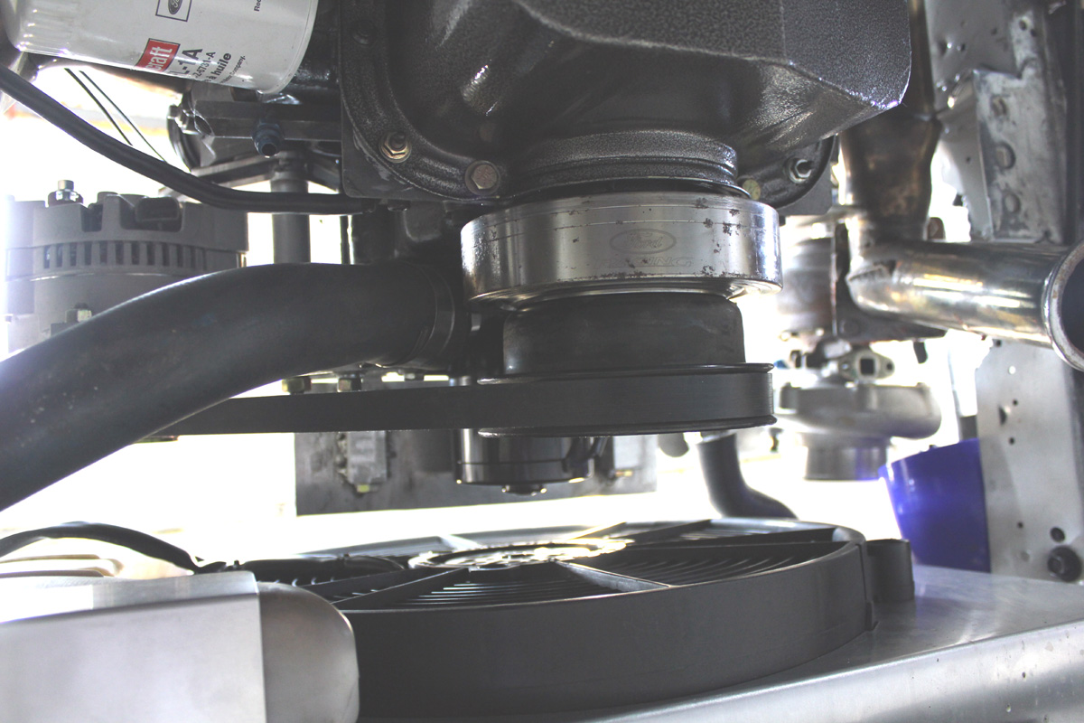
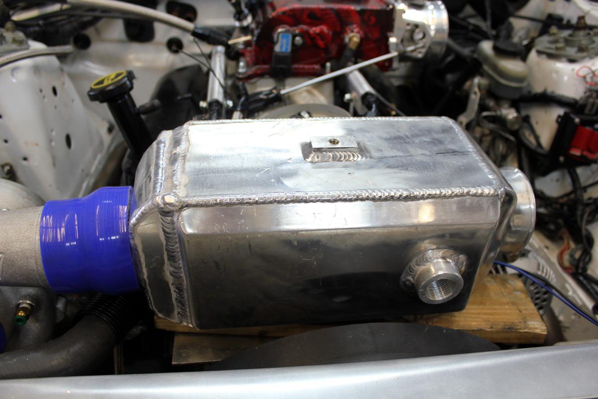
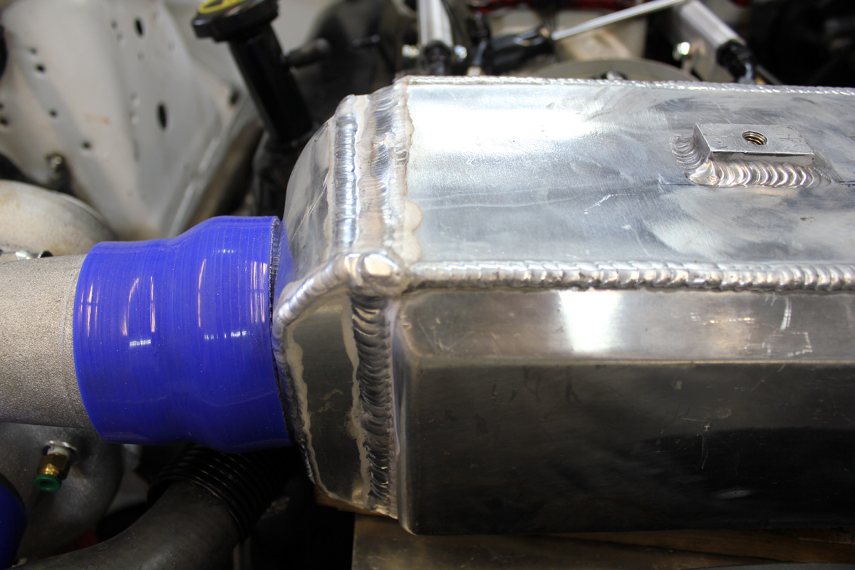
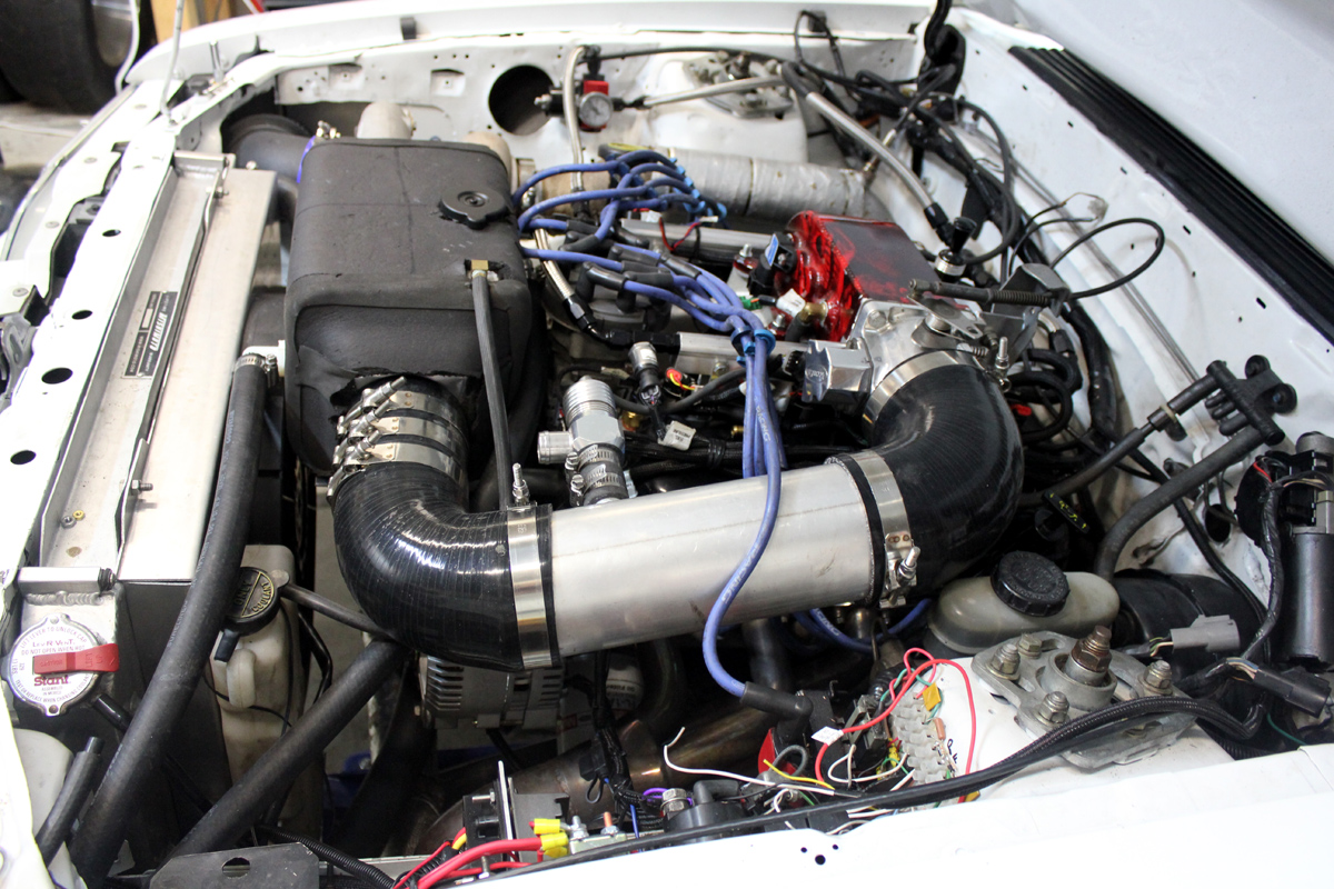
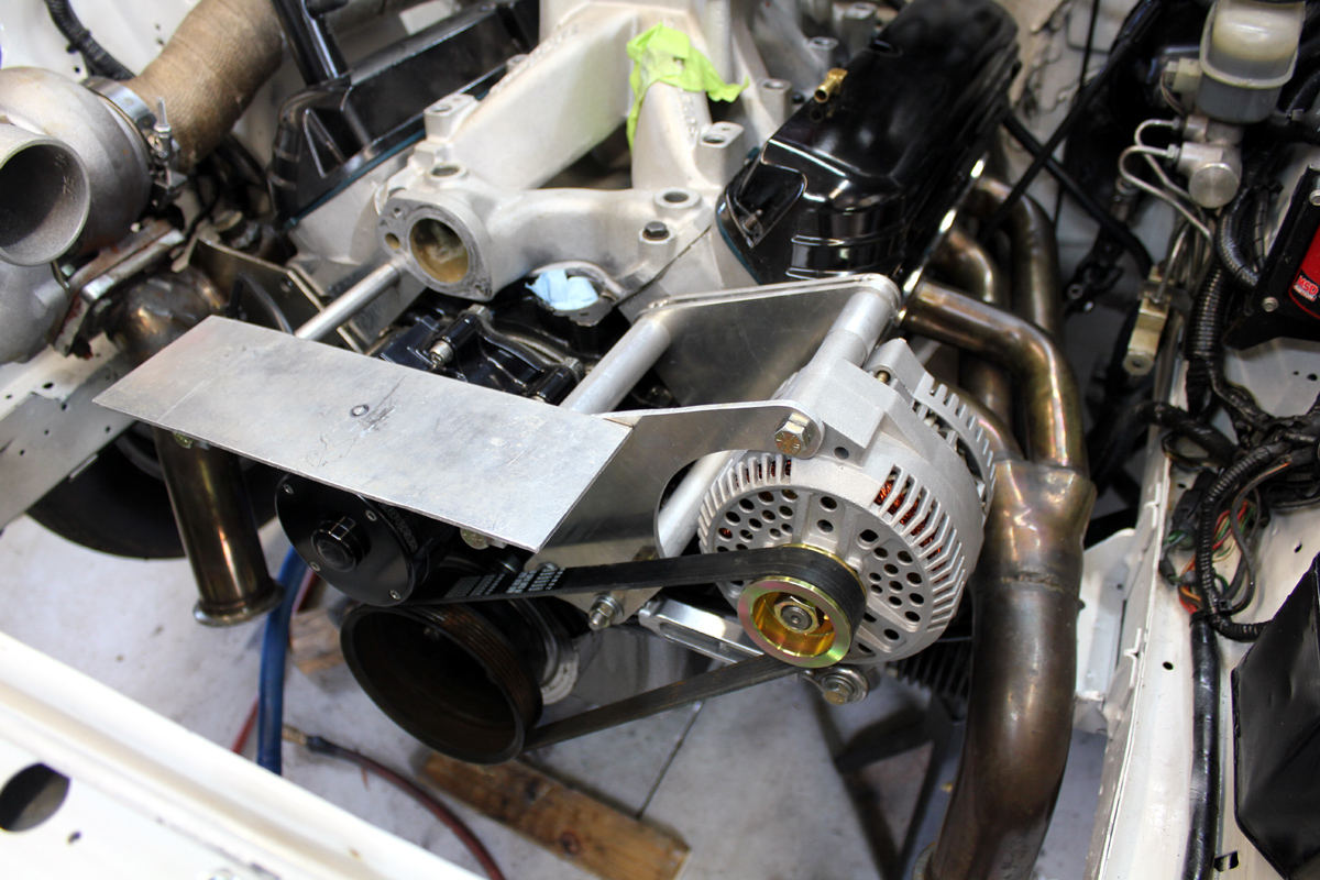
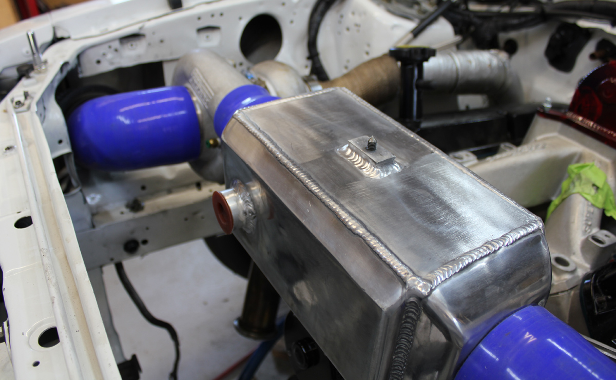
The intercooler sits on a shelf above the water pump. To avoid belt and pulley problems, only the alternator is belt driven. The brackets and spacers are all home made. The alternator is a New Tech Automotive N7771 from Summit Racing
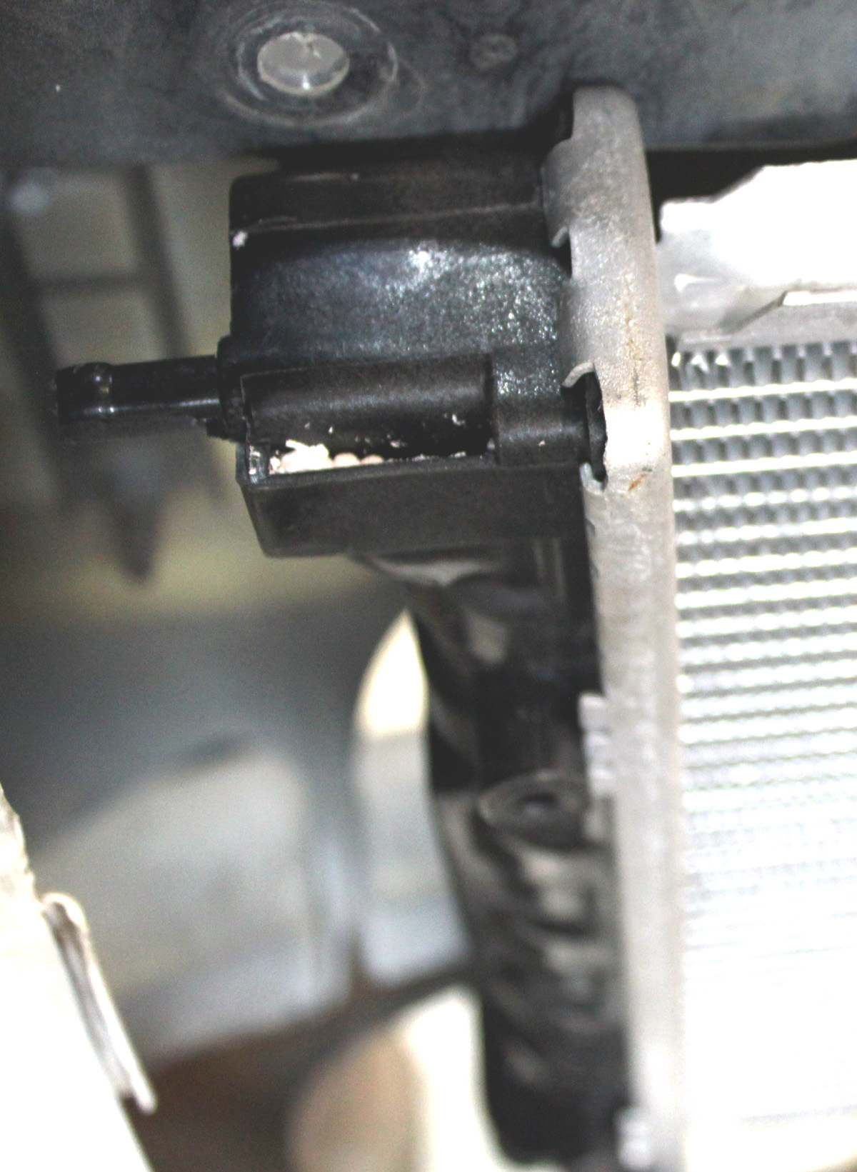
Water pump is a Meziere WP311S Summit link 55 GPM controlled by a Derale PWM controller. The controller samples off the water outlet near the thermostat with a home made adapter fitting.
The Derale water pump controller for the Meziere goes full speed at desired temperature of 160F.
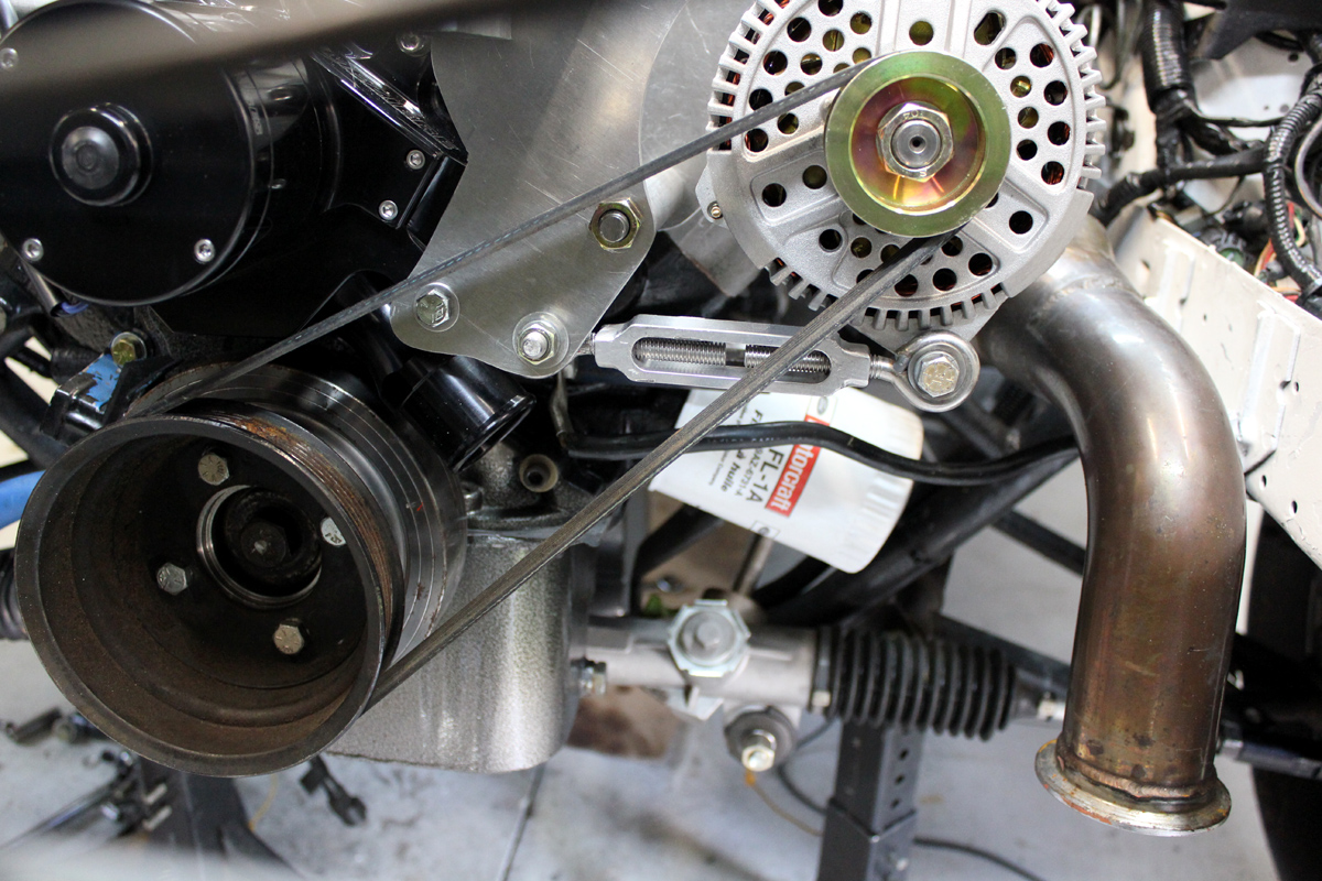
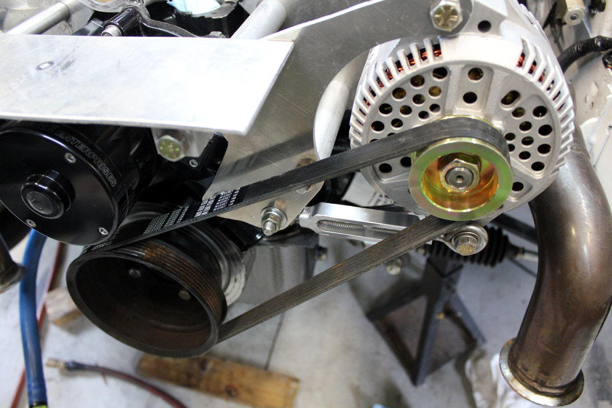
Another view of water pump and alternator.
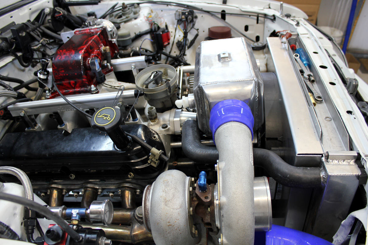
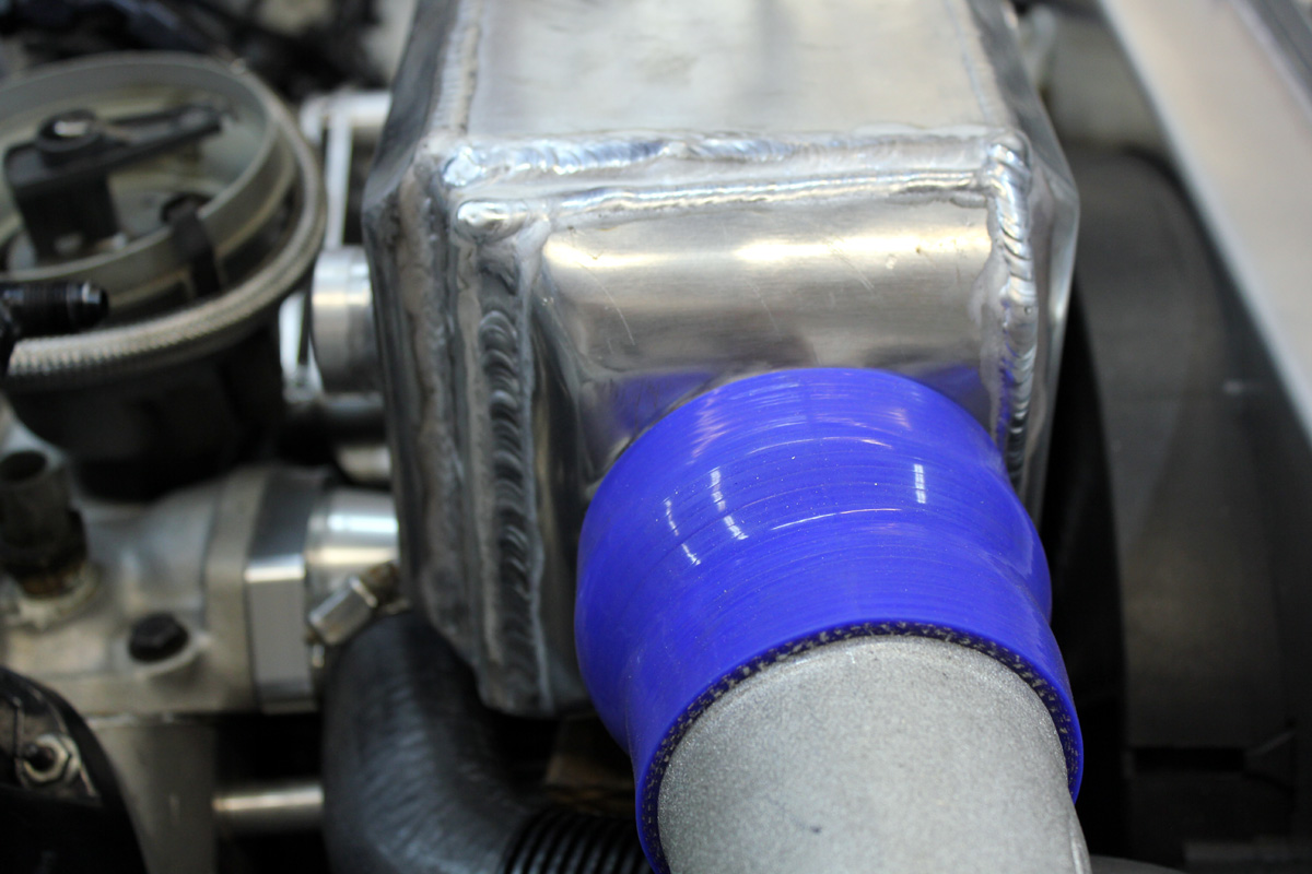
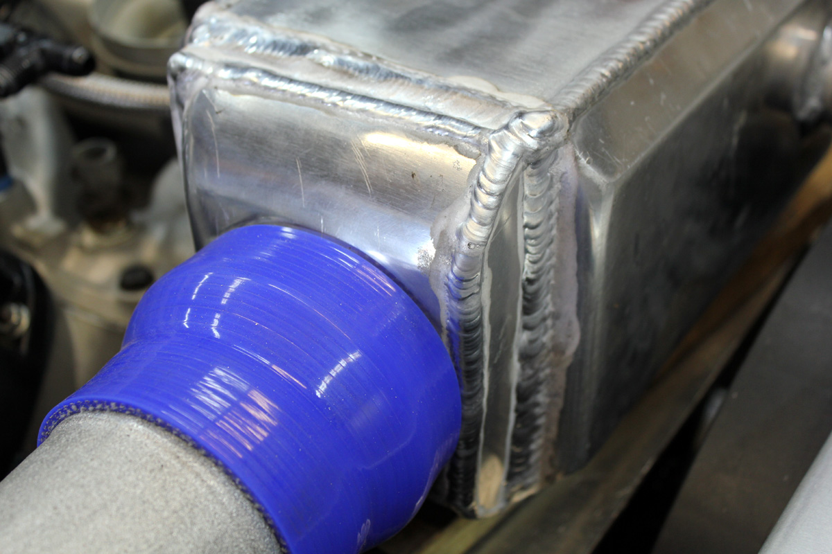
This is the unmodified intercooler. I had to modify it for a filling system.
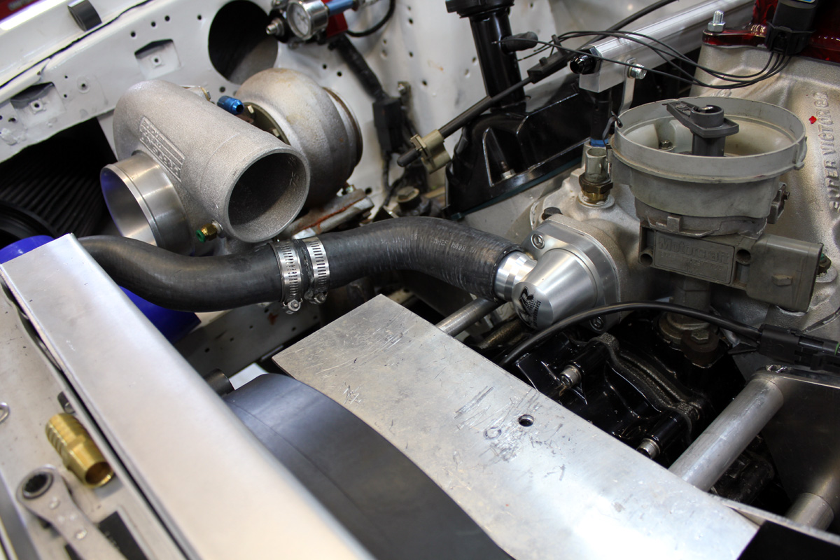
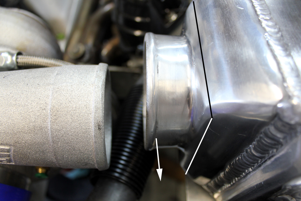
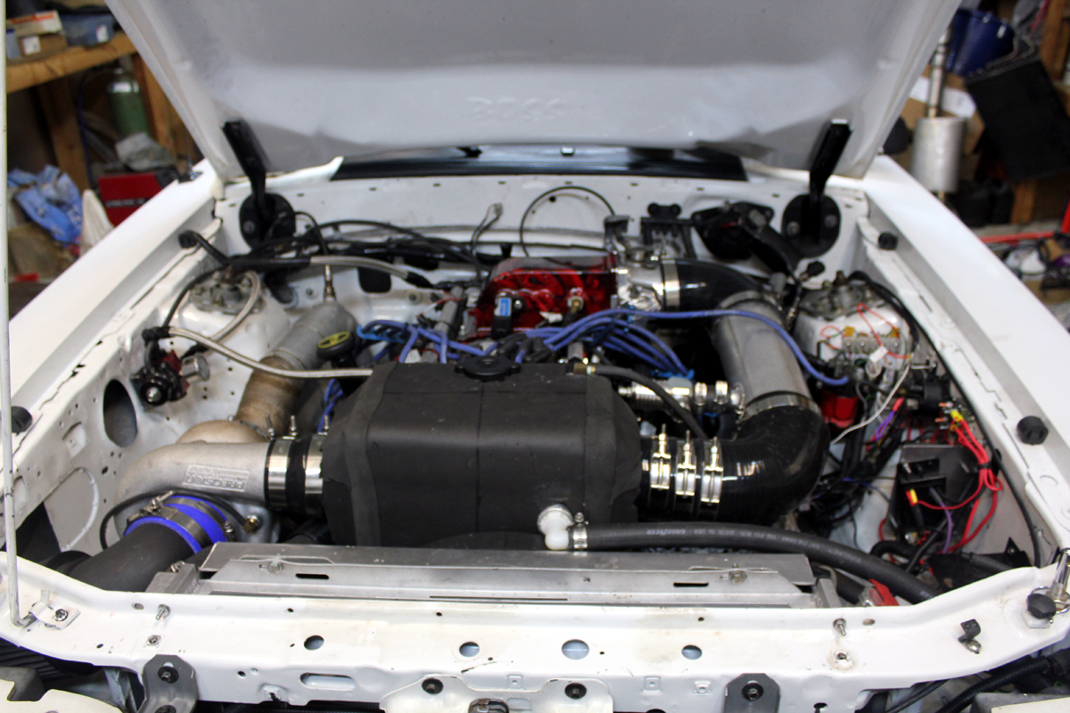
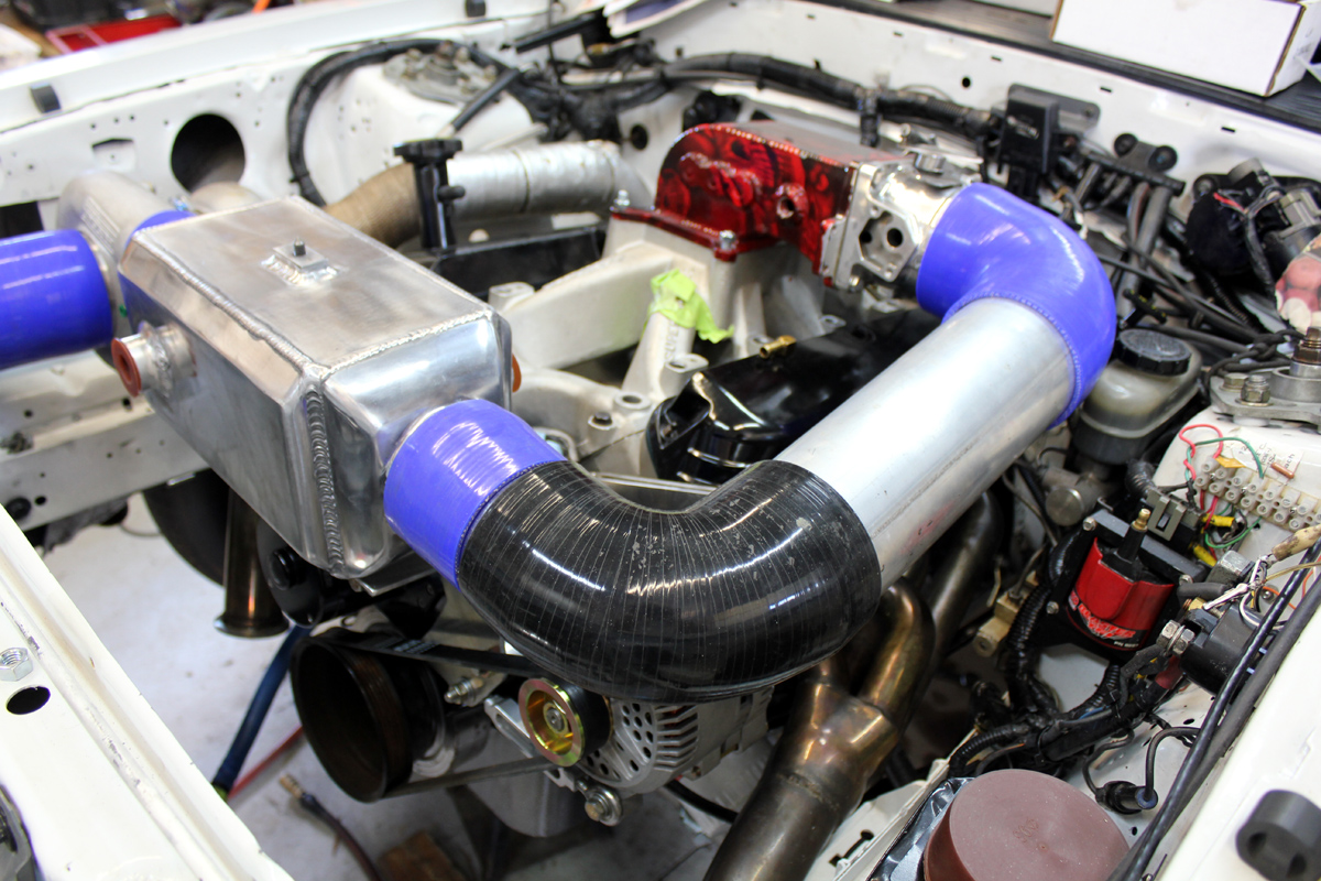
This is the planned air flow path.
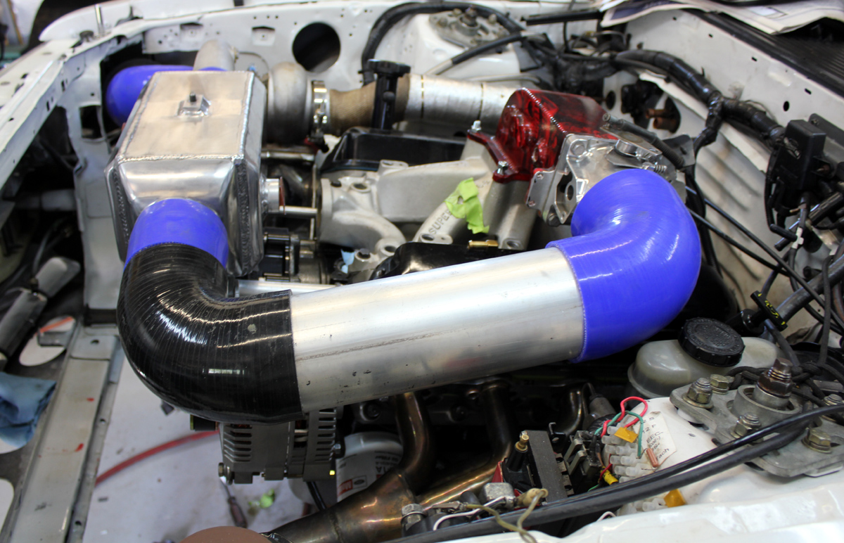
Another view planned air path through 4" pipes.
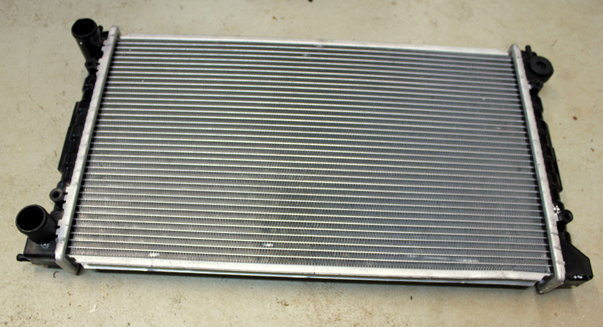
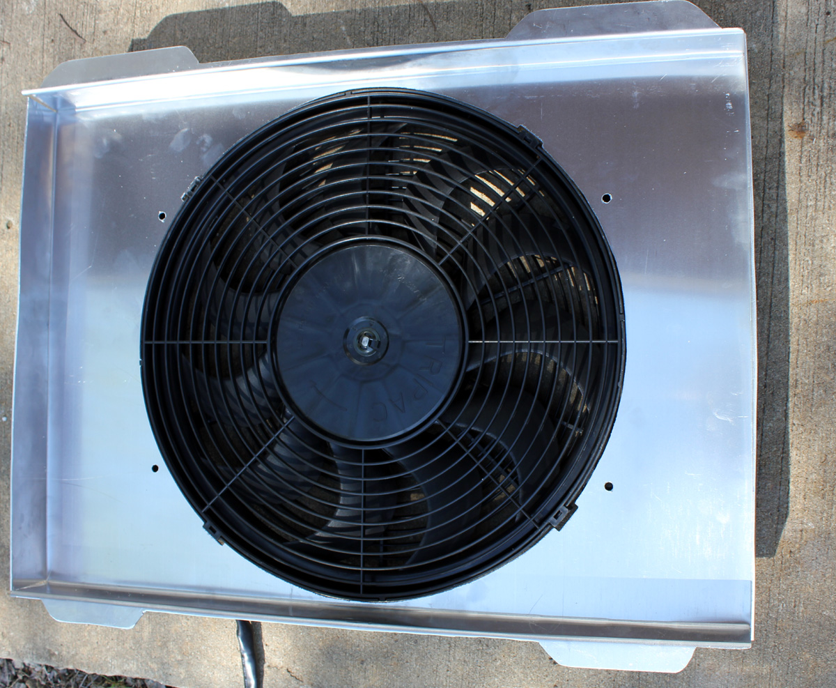
This is my home made radiator shroud that mounts a Derale fan. I tested several fans for air pressure. This was best combo for me. The fan runs at 20% speed all the time.
The fan goes into full speed when radiator outlet tank (cold tank) is at 145F. The radiator water outlet *always* has to be at least 15-20 degrees cooler than the desired engine temperature.
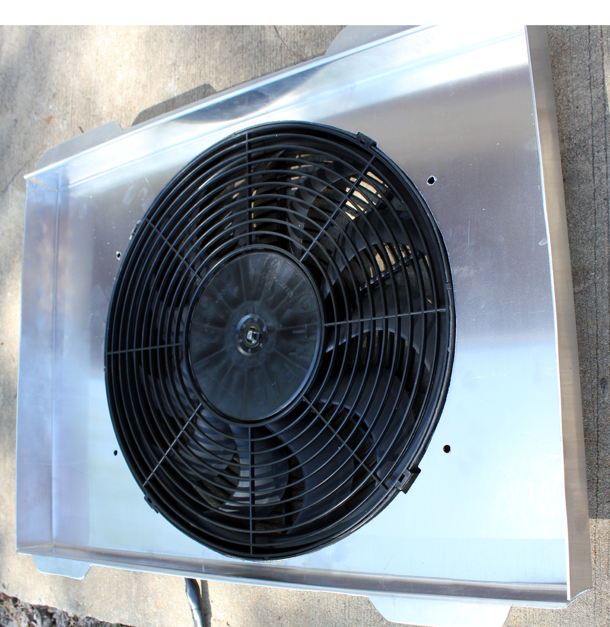
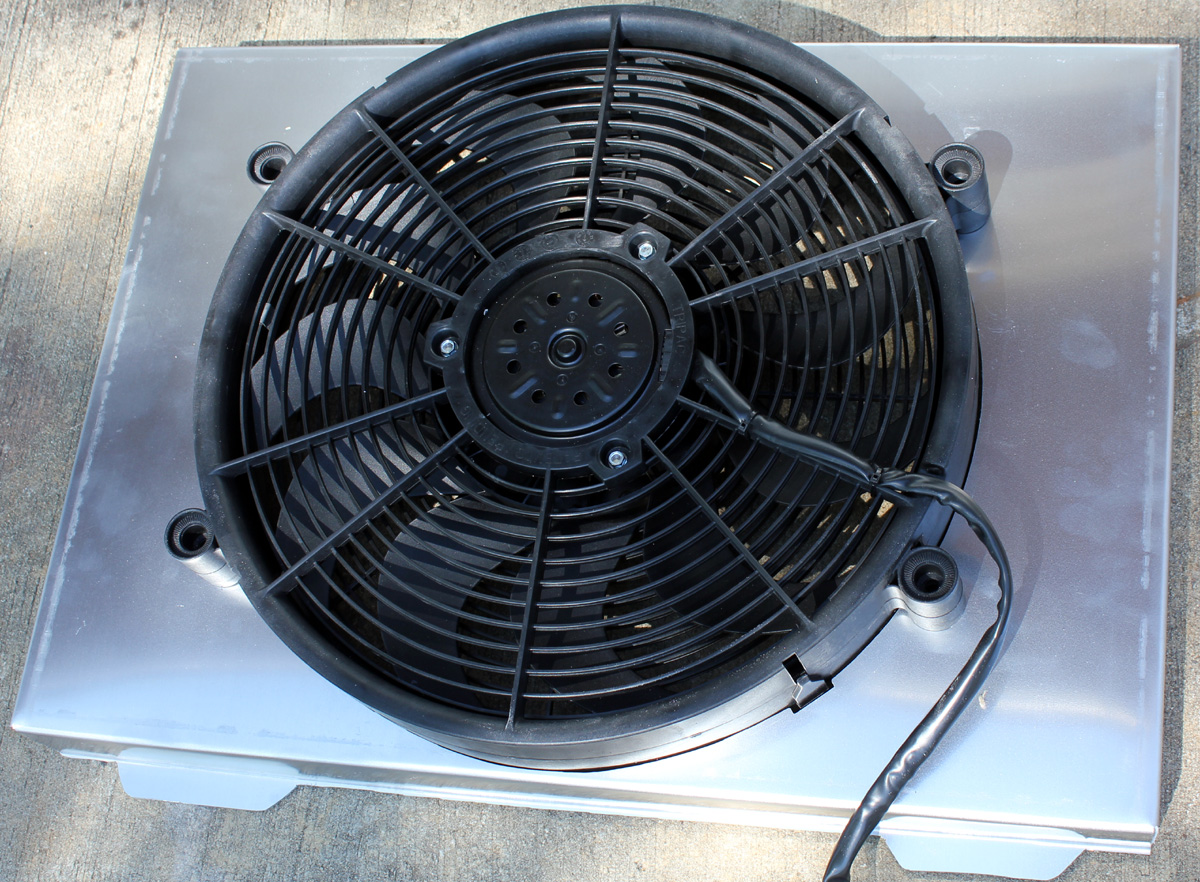
Another view of shroud
Passenger's side view of planned system