A 5/8th antenna element, by itself, actually has no gain. The 5/8th wave depends on radiation from a reflection or radiation from a second source to create gain. We can see this by looking at some basic antennas some distance above earth and away from ground planes or large reflective surfaces.
Here is a 5/8th wave vertical placed several wavelengths above earth, with a counterpoise system too small to support low angle reflections:
This antenna has four short radials in the counterpoise, and is .625 wavelengths long.
The pattern and gain is:
We see the peak gain is 7.22 dBi, and it has lobes all the way up to very high angles.
Now we can compare a 1/2 wave vertical dipole reference antenna at the same base height:
Gain pattern plot of 1/2 wave antenna:
We now see gain is 8.14 dBi maximum, and the gain along earth at zero degrees is 8.14 dBi. This means the 5/8th wave antenna gain is 8.14-7.22 = 0.92 dB less than a dipole. The 5/8th wave has a net LOSS of signal along the ground compared to a dipole at the same height, when both are remote from earth or large ground planes.
Let's look at a sloping-radial 1/4-wave antenna at the same base height:
We now see the pattern and gain is:
Gain is now 8.01dBi. In direct comparison we have:
| Antenna | dBi | dBd |
| 1/2 wave | 8.14 | 0 (reference dipole 4WL above earth) |
| 1/4 WL ground plane sloped radials |
8.01 | -0.13 dBd |
| 5/8th wave | 7.22 | -0.92 dBd |
The 5/8th wave antenna has a net loss over a vertical dipole when both antennas are located far above earth. The 5/8 wave antenna also has a net loss over a λ/4 (quarter wave) ground plane with drooped radials. The 5/8λ antenna has a net gain loss because it gets its gain from ground reflection some distance out from the antenna base, and this antenna lacks the gain enhancement from a large reflecting ground plane at base height, which means it lacks the second source below the antenna base.
This is why professional commercial antennas rarely use 5/8th wave elements, unless they are collinear above a second source or ground mounted over highly conductive earth. For example, at one time low frequency broadcast band stations used 5/8th wave verticals. The AM broadcast use of 5/8λ verticals largely stopped because of increased fading in fringe areas, and because the theoretical 3dB gain was rarely achieved at most locations.
Ham radio and CB radio marketing promotes this generally unobtainable gain as a characteristic of the 5/8th radiator, no matter where or how it is installed. This created a 3dB gain myth. In fact, unless the 5/8λ antenna is compared to a 1/4 wave vertical, and both the 5/8th wave and 1/4λ antennas are mounted directly over very large, dense, highly conductive ground planes, or unless the system contains a second radiating source that mirrors the 5/8λ element, they operate at a net loss. This article will walk through the basic antennas to explain how they actually work.
How Does a Vertical Omni Develop Elevation Pattern and Gain?
A vertical, like any antenna, changes gain as the antenna pattern changes. Removing energy radiated in some directions without adding too much loss will increase radiated field levels in other directions. Compressing the pattern through the addition of nulls concentrates the applied power in a smaller area of space, and that concentration of applied power is what we call "gain".
Assuming loss remains about the same, a vertical omnidirectional antenna develops gain through collinear effects. These collinear effects can come from additional physical in-phase radiating areas in the vertical antenna, from ground reflections, or from both effects. Gain associated with these effects closely follow the theoretical gain of a collinear antenna.
In the case of an antenna over highly conductive earth (or a flat infinite ground plane), effects of ground plane reflection are analyzed through use of an imaginary "image antenna". The "image" mirrors the real antenna's current distribution and height, with the reversed image appearing an equal distance below ground level. This is what causes the "collinear" earth image effect.
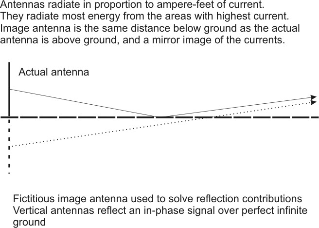
The graph below, from Jasik's Antenna Engineering Handbook, shows maximum possible collinear theoretical gain, in this case caused by the image:
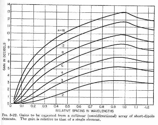
Referring to the graph and image antenna drawings above, we see a ground-mounted 1/2 wave vertical over infinite flat earth would have a current maxima .25λ above earth, causing an "image" .25λ below earth. This results in λ/2 (0.5 wave) spacing. If the reflection image is perfect, the theoretical maximum possible gain would be about 1.8dB over an antenna without any ground reflection gain. 1.8dB would be the gain of a λ/2 vertical or vertical dipole over a λ/4 vertical (quarter wave) with current maxima at the ground level.
Elevating the current maxima above ground will increase collinear spacing and increase gain. If we place the current maxima about 0.375λ above earth, which is what a ground mounted 5/8λ element does, we see theoretical image spacing is .75λ. Theoretical gain becomes 3dB over the ground-mounted 1/4λ vertical case, and 1.2dB over the vertical dipole or 1/2λ (λ/2) ground mounted vertical case.
There is a slight loss of gain in the 5/8λ antenna because a small section carries out-of-phase currents. These current are lower than the main currents, and are less area, so they have significantly less ampere-feet to cause radiation. The destructive interference at low angles is less than the reinforcement gain, so the overall antenna has gain, albeit less gain than theoretical. It works out over an infinite perfect ground plane a lossless 5/8th wave antenna has about 2.8dB gain over a ground mounted half wave vertical.
We will see models confirm the theory and, if both the reference and 5/8th wave antennas are lossless, 5/8th wave gain can range from just over 1 dB above a half-wave antenna in ideal cases, to a negative gain when the antenna is moved away from the perfect infinite reflective flat plane.
The 3dB gain of a 5/8th wave is a case that can only occur when something is wrong with the reference antenna, and the reference is a ground mounted 1/4 wave vertical. The unpredictability and potential of signal loss is why commercial two-way vendors, in the peak of industry times when engineers were skilled and antenna test ranges were used, almost never used 5/8th wave elements. The 3dB gain myth is a Ham and CB radio myth.
Mobile Antennas
Mobile antennas are unique, in that the vehicle roof acts like a large reflector to set up the image. This "reflection image" from the large roof and earth surrounding the vehicle can give the 5/8th wave gain over a 1/4 wave whip, when conditions are right. A 5/8th antenna in the air far above earth, however, is an entirely different situation.
A 5/8th wave is claimed to have 3dB gain over a 1/4 wl mobile antenna. Let's see if that is true.
Above....Pattern of a perfect infinite ground 1/4 WL whip antenna. This antenna has 5.15 dBi gain. Let's keep that in mind as a reference gain.
Above pattern is a 5/8th wave over perfect infinite flat ground. We see the peak gain is now 8dBi. Gain over 1/4 wave is 2.85db assuming NO matching system losses.
The same infinite-ground plane antenna, with a matching coil Q of 100, the 5/8th wave has 2.6dB gain over the reference 1/4 wave.
This is over an infinite size perfect ground extending to infinity.
This is a 1/4 wave antenna centered on a 1-meter radius plate five feet high (that's a big, flat, and high vehicle roof). It has 4.4dBi gain at zero degrees. Notice the pattern change. This is over infinite perfect earth. Real earth would suppress the lower angles further.
This is a 5/8th wave antenna centered on the same 1 meter radius plate five feet high (again, that is a large, flat, high vehicle roof). This "roof" is five feet high over perfect lossless earth. This antenna has 6.81 dBi gain at zero degrees. Notice a similar pattern change. This is because a vertical antenna's pattern is largely created by the reflection from earth around the antenna.
The 5/8th wave antenna gain with lossless matching would be 2.4dB better than the 1/4 wave in this case with the large roof as a flat ground plane.
The above is a 5/8th-wave antenna centered on a large flat roof over good flat soil. It has -4.56dBi gain at 2 degrees.
Maximum gain is now only 3.07dBi.
At 2 degrees takeoff the 1/4-wl antenna over good soil with perfectly flat terrain has -6.75 dBi gain. Maximum gain is now 3.08 dBi.
The gain of a 5/8th wave over a 1/4 wl antenna at 2 degrees is now 2.19 dB, but the peak gain of the 5/8th wave is only .01dB different than the peak gain of a 1/4 wave antenna! The 2 degree gain of the 5/8th wave is mostly because of increased height over lossy earth. The 2 degree gain of the 5/8th wave is not because of antenna gain, but because of height change. It puts the current further above earth.
With a normal mid-size roof contour 5/8th wave gain is now -4.64dBi at 2 degrees elevation. Maximum gain is now up slightly to 3.2dBi.

With a normal sloped roof shape and mid-car size ground, the 1/4 wave has -6.59dBi at 2 degrees TO. Maximum gain is 3.05dBi.
5/8th wave gain is now 1.95 dB over a 1/4 wave antenna at 2 degrees, but the peak gain is only .15dB better!
The smaller the roof and/or the less centered the antenna, the less gain advantage for a 5/8th wave. This occurs because 5/8th wave antennas develop gain from ground reflections.
Lower height roofs also have less gain difference, and shape of the roof greatly affects pattern and gain.
The 2.85dB theoretical gain is only for a perfect lossless loading coil antenna over perfect infinite flat ground plane.
In the real world the actual gain difference between a 1/4 wave antenna and a 5/8th wave can be anywhere from no gain or a very slight loss up to a maximum of 2dB gain over a 1/4 wave. The 5/8th wave is never really worse, explaining why people have no problems using them. This is true for any repeater antenna height. The primary advantage of a 5/8th wave in mobile operation is increased antenna height, not from an actual gain increase.
The further from ground, the less advantage a 5/8th wave has.