The Knight T-150 and T-150A have a generally poor reputation for spectral purity. As originally designed, the T150 and T150A have very high spurious signal levels. Although not perfect without major redesign, they are easily improved if we take time to understand the flaws.
The primary flaw in the Allied Knight T150 series is the very poor choice of VFO frequency, and poor unwanted VFO fundamental and/or unwanted VFO harmonic rejection by following stages. Poor harmonic rejection is caused by marginal Q tuned circuits between stages, by grossly excessive coupling between stages, and by low output tank Q on 80 meters.
The T-150 uses a very poor choice of VFO frequencies. On 80 meters, the VFO runs between 1.75-2 MHz. This is typical of many VFO's, and was done to move the VFO off straight-through bands. Running on straight through bands, like an 80-meter VFO on 80 meters, can aggravate oscillator pulling, and in severe cases, cause early stages to oscillate. This is normally not a problem on 80-meters, because a spurious 1.75 MHz below or above the band is a fairly large percentage of frequency away. For example, on 80-meters, the 1.75 fundamental is 50% of the operating frequency. The third VFO harmonic is on 5.25 MHz, about 50% above the 80-meter band.
On 40-meters, the T-150 VFO operates between 3.5 and 3.713 MHz. This creates a major spurious signal issue. Now, on bands on and above 40 meters, the spurious multiples are only 3.5 MHz. above the band, or below the band. This means, on ten meters, the VFO spurious signals are only 12.5% below and above the ten-meter band. This low percentage difference can cause problems filtering spurious signals, and increases the number of spurious signals.
Here is the original spectral plot of a T150 on 80 meters:
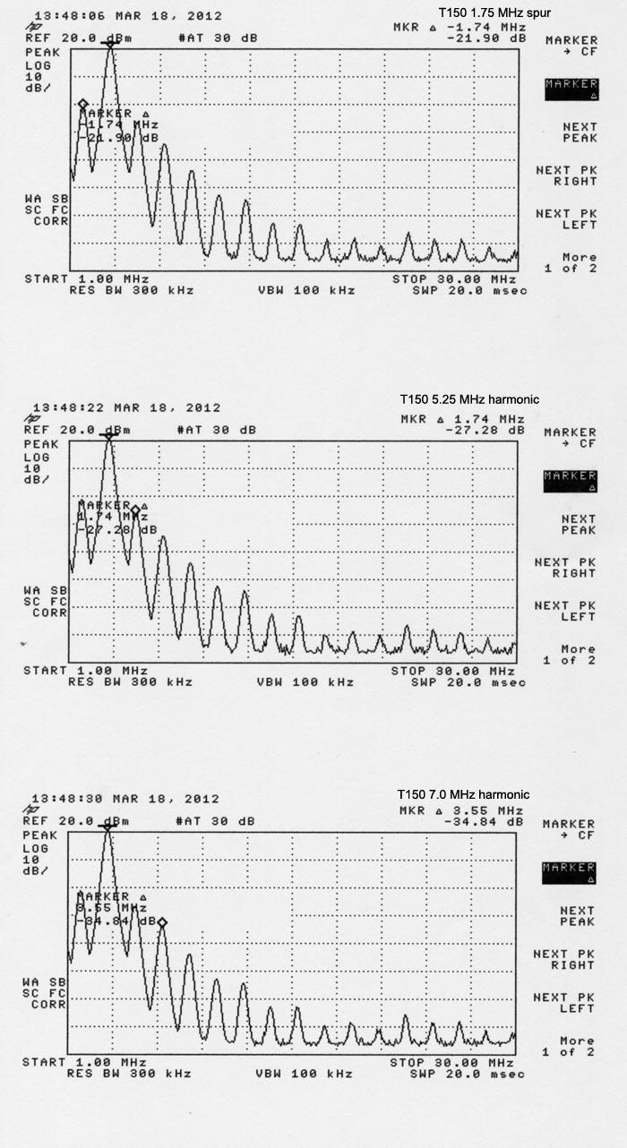
160-meter signal, while on 80 meters, is only -21 dBc below 80 meter desired signal. Notice spurious signals appear at every multiple of the VFO frequency, every 1.75 MHz.
5.25 MHz signal, the third harmonic of VFO, is -27.28 dBc.
This is primarily caused by over-coupling between stages and poor selectivity in oscillator and buffer circuits, and aggravated by low tank Q on 80 meters.
7.0 MHz signal is only -35 dBc 80-meter signal. This is primarily caused by low tank Q on 80 meters. I'm working on a fix for that.
Modifications
SAFETY
The T-150 does not have a bleeder resistance across the lower electrolytics in the power supply (350V B+ line). I added a 50k 7 watt resistor from one terminal of the 40 uF electrolytic to chassis ground, although a 100k 2 watt metal film or oxide resistor will work.
PERFORMANCE CHANGES
Note: These mods are subject to change as I spend more time working with the T-150.
Referring to the schematic below:
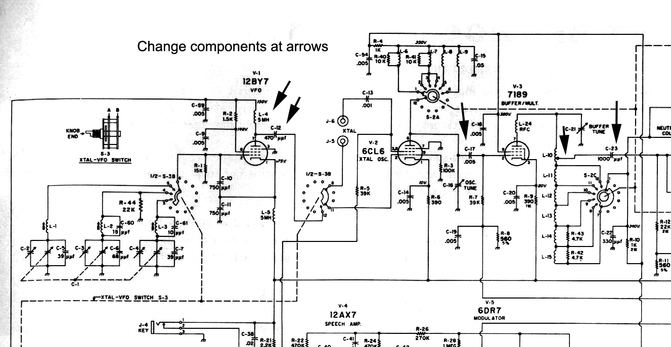
Looking at the schematic above, we see the T-150 is seriously over-coupled between stages, and has far too large of an RF choke on the VFO. For example, L-4 and C-12 can be used to form a high pass filter. This is usually desirable, because lower harmonics of the VFO almost always provide far too much drive anyway. In this stage , knight used 5 mH as the choke, offering a very high impedance far below the AM broadcast band. Aggravating the situation, they then used a 470 pF coupling capacitor. This extends low-frequency response of the VFO output system down into the 100-200 kHz range, far below the lowest transmitter frequency of 3.5 MHz.
This pattern of poor component value choice extends through all RF stages, including the 6CL6 "oscillator" stage (used as a buffer in VFO mode) and 7189 buffer/multiplier stage.
To correct this, we can:
- Change L-4 to 100uH such as JW Miller 4632
- Change C-12 and C17 to 27pF 1kV any common style, disc or mica
- Change C-23 to 68pF 1kV. Any common style, disc or mica
- The tap at L-10 moves to tube end near parasitic suppressor.
This results in the following change in output:
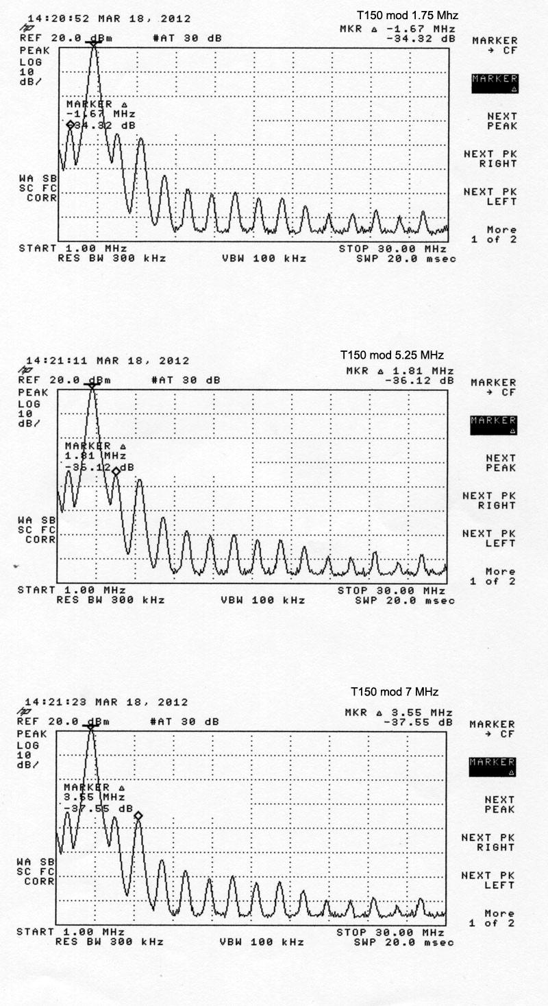
160 meter feedthrough is now -34.3 dBc. This is a 13 dB improvement.
5.25 MHz harmonic of VFO is now -36.1 dBc. This is an 8.8 dB improvement.
7 MHz harmonic is now -37.6 dBc. This is a 2.6 dB improvement. This harmonic does not improve much with driver system mods, because it is primarily caused by poor tank operating Q on 80 meters.
Deeper Changes (under work)
The 6CL6 crystal oscillator/buffer stage lends itself to easiest changes when using a more involved modification. For 80 meters, I replaced L-6 with a choke from Mouser Electronics. I used a Vishay-Dale part number 70-IMS5-22 in parallel with a 27 pF 1 kV capacitor. This changed 160 feedthrough from the -34 dBc obtained with the simple mod to -45 dBc, a 10 dB improvement over the simple mod and -24 dB better than stock!
With this single change, the unwanted signal on 5.5 MHz changed from the -36 dBc obtained in the simple mod to -55 dBc . This is a -19 dB improvement at 5.5 MHz over the simple modification, and about -27 dB better than stock. At this point, the T-150 is not much worse than any other rig on 80 meters.