Baluns on Log Periodic Antennas
|
Baluns on Log Periodic Antennas |
|
My experience with logs is limited to some broadband commercial TV band arrays used in MATV and CATV head ends. I worked as an independent consultant for two companies that manufactured heavy duty multiple channel antennas for commercial installations. In these installations, pattern and SWR was everything. Because the antennas were used to feed video to thousands of customers, and often installed hundreds of feet above ground, the antennas needed clean tight patterns without ghosts caused by standing waves. I actually became involved because some commercial antennas had ghosting and pattern problems. These problems were related to improper feed systems. This is a problem that appears not only in commercial TV antenna designs, amateur antenna manufacturers also place baluns at the incorrect location in LPDA arrays or instruct users to route the coaxial feed cable incorrectly. This can cause substantial RFI and all sorts of unusual problems, such as excessive RF into house wiring or consumer electronics. Improper cable routing can also cause odd SWR problems. If we consider what the balun does, we can see how the mistake occurs. I was first made aware of an amateur radio log periodic feed problem by a friend who had severe consumer RFI problems whenever he ran an amplifier. The following describes what we found. What's Right or Wrong with LPDA FeedsCold BoomsSome antenna manufacturers suggest taping or attaching the coaxial feed line along the length of the boom, back to the mast. This would work perfectly in any antenna with a "cold" boom. The coax shield and the boom would be at the same potential, and the boom would also be grounded directly to the mast and tower, placing the coax shield, boom, mast and tower all at the same RF potential, hopefully zero or near zero RF potential. These log designs almost always have a high impedance transmission line, generally 200-300 ohms. 200 ohm systems are commonly used in transmitting arrays, through a 4:1 balun, to a traditional 50-ohm feed cable. For receiving, balanced line impedance is increased and the log optimized for a 300 ohm feedpoint, allowing a 4:1 balun to convert to 75 ohm cable. As a general rule though, logs work better with lower impedance transmission lines. Hot BoomsSome log periodic designs use the boom as one conductor of a two-conductor balanced transmission line. This is a very good thing to do, if the system is managed properly, because it is possible to build a very low impedance balanced transmission line. Lower impedance balanced lines in the log tend to produce better overall log performance. The Tennadyne log periodic is one example of a "hot boom" antenna. In hot boom antennas, two booms run parallel over the length of the array. The booms are insulated, or should be insulated, from the mast and tower. Elements alternate connection to the upper and lower, or left and right, booms. This inverts phase, as transposing adjacent element connections in cold boom antennas does.
A balanced transmission line, such as the balanced line feeding elements in a log periodic, must have the following: Equal and opposite voltages from 1 and 2 to point A, and from 1 and 2 to point C, at each end Equal and opposite currents in 1 and 2 at any point along the line Equal and opposite voltages at point B all along the line
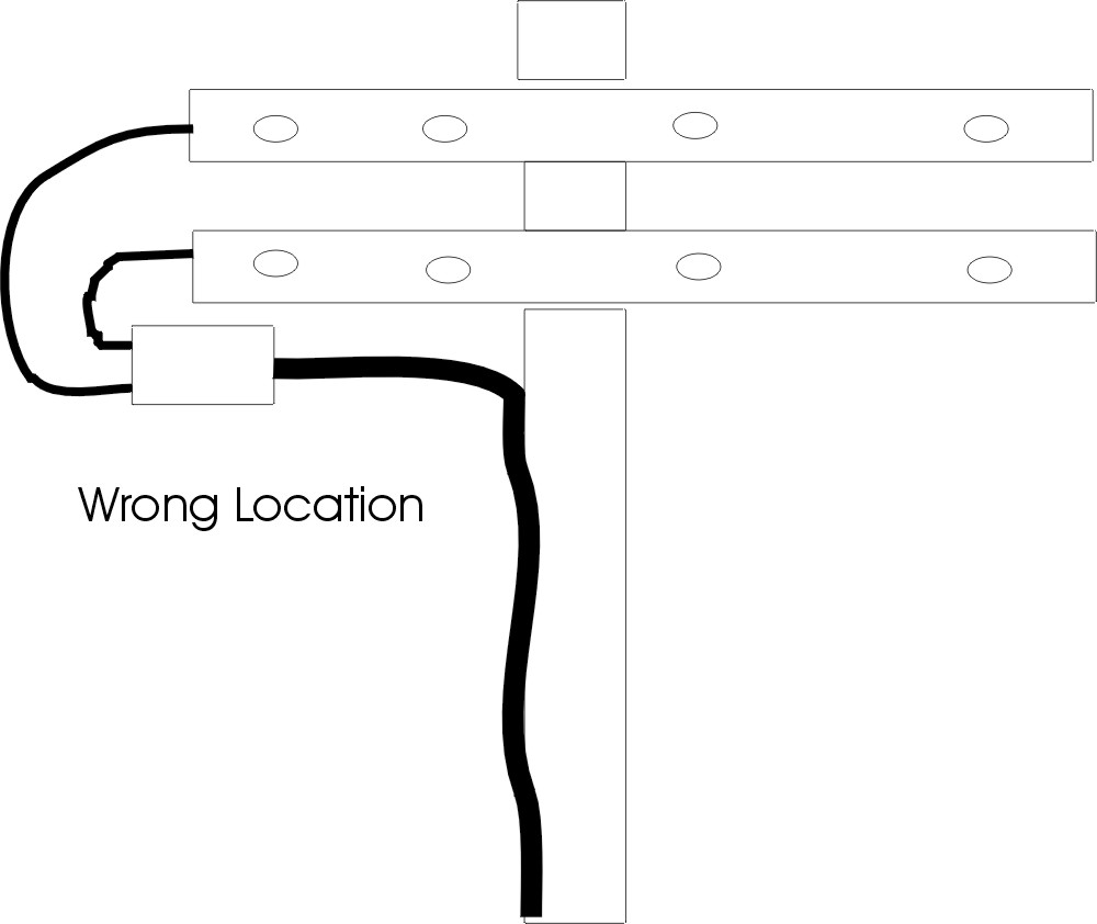
Unfortunately, some instructions route the coaxial feed line directly along the hot boom. This is exactly like taping coax to one conductor of a balanced open wire transmission line, because the boom is part of a two-wire transmission line! Both booms are electrically hot, just like conductors in any balanced transmission line. Each boom is, after all, feeding half the elements!! Obviously the boom cannot feed elements properly without equal and opposite voltages, and equal and opposite currents, along each boom.
When coax is taped to the balanced boom, either balanced conductor line 2 is forced to zero, or the coax shield is forced above ground. Actually a portion of both happens, with the coax shield becoming a radiator and boom conductor 2 becoming more at the potential of point B.
This forces the coax to radiate and create RF ground loops, while also starving half the log elements of voltage and current. Any additional conductor or feed cable paralleling the boom, especially one held directly against the boom by tape or wire ties, will be significantly excited by boom currents and voltages. Cables routed against or near the hot boom (both booms are hot when the booms are used as transmission lines) will have the voltage difference between the boom and the tower at the cable exit point exciting unwanted external currents in the feed line shield. The feed line shield will also be excited by magnetic coupling by magnetic fields created by boom currents. In effect, the coaxial transmission line shield becomes a third transmission line conductor, driven by boom currents and voltages through the very tight mutual coupling. The coaxial feed line shield is supposed to be at ground potential. It must attach to the antenna in a way that keeps the shield at "ground potential". Otherwise, the shield will radiate and also bring significant RF voltage away from the antenna. At some point we must have a properly thought-out balanced to unbalanced transition. As with any balanced transmission line, the hot booms (or a balanced two-conductor line running along a cold boom) should either be symmetrically spaced a reasonable distance in relation to the two conductors forming the balanced line, or placed several conductor spacings away from the hot conductors that form a two-wire balanced line. Ideally an external feed line exiting the antenna would not be within a few feet of large diameter hot booms. A second method that only works with a 50 ohm feed (this will not work with 200 or 300 ohm feeds) would be to tape the coaxial feed line along the shield attachment point boom and treated like a part of that boom.
In this example, the coaxial cable shield is much closer to the hot lower-boom than the hot upper-boom. We would never dream of lashing a cable, or any external conductor, to one conductor in a two-wire balanced feed line feeding a dipole. Commonly available information instructs us to keep all external conductors several balanced-line-widths away from any unshielded balanced line.
There are two ways to correct this problem:
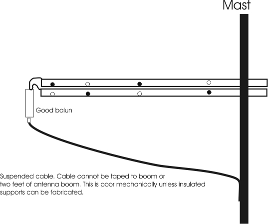
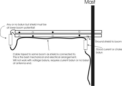
ConclusionFor proper operation the feed line must be suspended at least a few feet below the hot booms all the way from the balun's unbalanced connector to the tower or mast (this works with any balun and any impedance log), or a second 1:1 current or choke balun must be added at the mast (this works most effectively or reliably when a CURRENT balun is used at the feedpoint, or when the feedpoint requires a 1:1 balun and no feedpoint balun is used). This will greatly reduce RFI and improve the antenna pattern and gain.
© 2004 W8JI
|