Transmission Angles
Centering the transmission is reported to be necessary. This is an analysis of how centering affects gear alignment inside the transmission.
First, let's look at what Tremec says. As of March 3, 2015, this is all they say:
A: To say you have an improperly indexed bellhousing is also to say that your transmission is improperly aligned with the engine in front of it. What this means is that the input shaft is not sitting true into the pilot bearing, which can cause a long list of transmission-related problems; as small as hard shifting or as big as total product failure. We are currently working on putting together our own online installation guide to address these issues. However in the meantime, there are several articles online that explain the principles of driveline angles and how to properly set them. Here is a link to get you started: http://www.carcraft.com/howto/91758/index.html
The link isn't even a good one. It is for rear ends.
I found this link:
http://www.hotrod.com/how-to/transmission-drivetrain/ctrp-0404-bellhousing-alignment/
In it, they say:
![]()
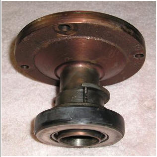
Alignment is important three ways. The Z and X axis (normally checked), and the crankshaft centerline to transmission case front angle (which should be exactly 90 degrees) that is almost never even considered
1.) The transmission input bearing is a fulcrum point for alignment issues for deflection in inches
2.) The transmission case face to crank centerline also directly affects alignment. The alignment degrees should be exactly 90, and the angle error is NOT stepped up or down by shaft lengths
3.) The crank pilot centerline to transmission input bearing center determines distance alignment errors through a lever action, like a teeter totter! Any error is stepped down by the ratio of shaft length outside the input bearing to contact point of the input shaft inside the transmission
4.) I will assume the transmission is constructed perfectly inside, without any alignment error internally and it holds gears and the transmission holds internal shafts perfectly rigid in alignment (good luck on this with hundreds or, depending on the gear and the engine, many thousands of lb/ft torque distorting things!)
![]()
Crankshaft to bellhousing transmission center location errors
![]()
Any centering error of the shaft or transmission, measured at the bell, is translated by the ratio of shaft outside the transmission bearing center (B) to length inside the transmission at the contact point to F. If we look all the way at the end of F, it might be dimension C. In this example the very worse case alignment would be C/B * error = actual internal error
Let's say we have .005 inch error outside in transmission centering, and everything else is perfect. The internal distance error would be .005* (C/B) = .005 * (3.7/6.8) = .005*.544 = .00273 inches.
The degree error would be the same. If we had a .05 degree error outside, it would be a .05 degree error inside. Angular error is not changed or modified by lever action.
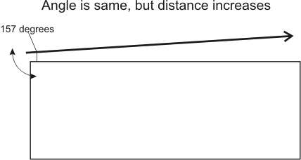
This works like a teeter-totter, or a triangle or parallelogram geometrically. With a fixed degree error, a long physical distance between points means far more than a small distance angle error. The distance error can also be multiplied or divided by lever ratios to the pivot point or fulcrum. Think about it this way; let's say we are installing a long fence. We measure two points 120 inches apart, and make a 1 inch mistake. At 240 inches, the error is the same number of degrees but becomes 2 inches.
Looking at the face, shaft, and bellhousing we find:

This is why the transmission face distance error to the crankshaft center line (through the bellhousing) means far more than the centering of the transmission in the bellhousing hole (or input shaft centering to the crank center). That angle should be 90 degrees, but is so difficult to measure accurately I doubt anyone does it. Measurement error would probably exceed machining errors because almost no one can measure small right angle errors accurately. I have machine equipment, and cannot measure .05 degree errors. If dust gets on the surfaces, or a hair gets in the way, the error can be .002 inches or 0.2 degrees or more.
Angles and Distance
Putting size into perspective, the average thickness of a human hair is 0.004 inches.
Let's say the input shaft tip is 6.8 inches forward of the input bearing center, and we measure a bellhousing hole error of .005 inches down. This crank centerline error shifts the transmission bearing down .005 inches to the crank, which is the same as lifting the input shaft nose by .005. This moves the input shaft gear down .005 * C/B or .00272 inches at the furthest point of the input shaft. If the input gear was 1.5 inches forward from the end where the slider teeth are, the start of the gear would shift down .001618 inches, or less than half a hair.
Now let's say the locating hole center is perfect, and the transmission top is .005 inches back from the shaft centerline. This .005 inch error is equivalent to moving the input shaft tip up .005*B/D = .01236 inches. This .005 inch backward move in relation to shaft centerline position is .01236/.005 = 2.47 times the error caused by hole centering on the crank. This means if the paint on a perfectly machined bellhousing is .005 inches thicker at the transmission top edge, it is like having the hole center .01236 inches off.
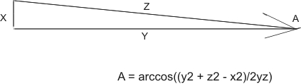
Angle A is the arccos (or also written cos-1) of (y squared + z squared - x squared ) over 2 times y times Z For .005 inches deviation measured over 6 inches, the angle is: cos-1 (6^2+6^2-.005^2)/2*Z*Y = 71.999975/72 = cos-1 of 0.999999653 = .047746469 degrees.
If we offset the bearing centerline on a six inch long shaft by .005 inches, the degree error is less than .05 degrees. A .005 inch error measured over 6 inches spacing causes a degree alignment error of a little less than 0.05 degrees.
Now you see why I am starting to have a problem with, or at least be very skeptical about, the idea that measuring hole center is meaningful.
Since we cannot measure what matters, we measure something we think (and everyone says) solves the problem. We make something to be a problem, we ignore what is probably a much larger problem source, and we fix the problem we invented.
I've been installing stick shift transmissions for about 40 years or more, and never measured the locating hole center one time.