Coaxial Cable Leakage
|
Coaxial Cable Leakage |
added coaxial cable measurements July 11, 2012Related pagescoaxial lines and shielded wires how a shield works (skin depth) Bench Test Fixture July 2012Data for common mode current ingress into cables is mostly non-existent. The data that is available is not very useful, because test method details are not readily available. A manufacturer might tell us shielding effectiveness is so many dB, but what does that really mean? Another problem is the abundance of opinions and advice regarding shields and shielding, and generalizations about what does what inside a cable, including functionality or operational contribution of shields and foils inside a cable. Advice and information in amateur radio circles seems to be based on opinions, observations, or feelings about VHF or UHF performance, or how audio cables work. Thinking about this problem, as it relates to amateur radio, I decided to build a fixture to directly measure coaxial cable ingress from common mode shield currents. Building a fixture for lower frequencies is not that difficult, because groundplanes and shields are very predictable. They are easy to test and verify. The concerns for an "outside-in" measurement are:
I constructed the following fixture:
Loads match cable impedance RF load current is found with a HP RF level meter across the load High power RF source is an IC751A through an ATR30 tuner Current sample is a calibrated clamp-on RF current probe
I normally set shield current at either 300 mA or 1 ampere. Load current is measured by voltage drop across a 75-ohm resistor using a high impedance RF millivolt level meter. This is a significant amount of common mode current. Verification of FixtureTo verify the fixture, I included a dummy port with load near the measurement connector. I can verify three ways:
In the first two cases, my meter stays out-of-lock. Lock occurs with about 0.2 mV, while normal readings (so far) are in the 5-40 mV range. This shows an insignificant error. In the last case, the fixture shows within 0.5 dB of zero loss (the error is from calibration or tracking errors).
MeasurementsRatio of outside shield current to center conductor current for 8-ft cable length:
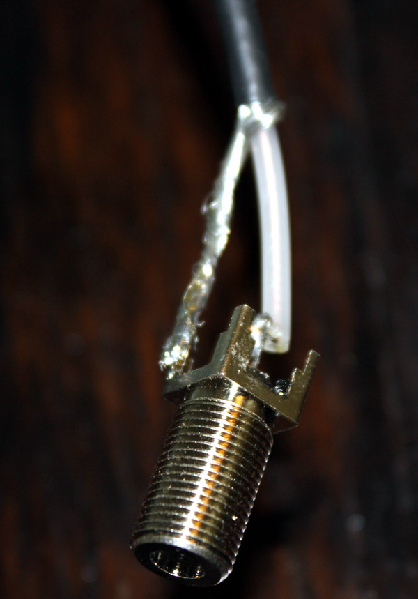
Removing braid has a very noticeable effect on common mode impedance, because injected current changes. It does not necessarily change common mode coupling very much. Even on 160 meters, innermost foil dominates shielding. The Dish Network cable was just removed after being outside since 2008. It is a foil / braid non-flooded cable. It appears to have excessive resistance and bad connections on the outer braid, because flexing changes RF current about 10%. Flexing does not change ingress very much, the inner bonded foil must be intact. Connector MountingConnector mounting is critical. For good CM rejection, cables entering boxes should mount on a common metallic wall. The wall must have significant conductor area to maintain low impedance between connector grounds, not moderately-sized circuit traces or wires. The exception is at an intentional interface to a shield isolation system. This is a commonly seen connector wiring method. Techniques like this are often used where cables enter plastic boxes.
Here is how a connection method like this, with 3-inches of coax, impacts measurements of
Some ConclusionsInteresting conclusions can be drawn from this data, and observing system behavior.
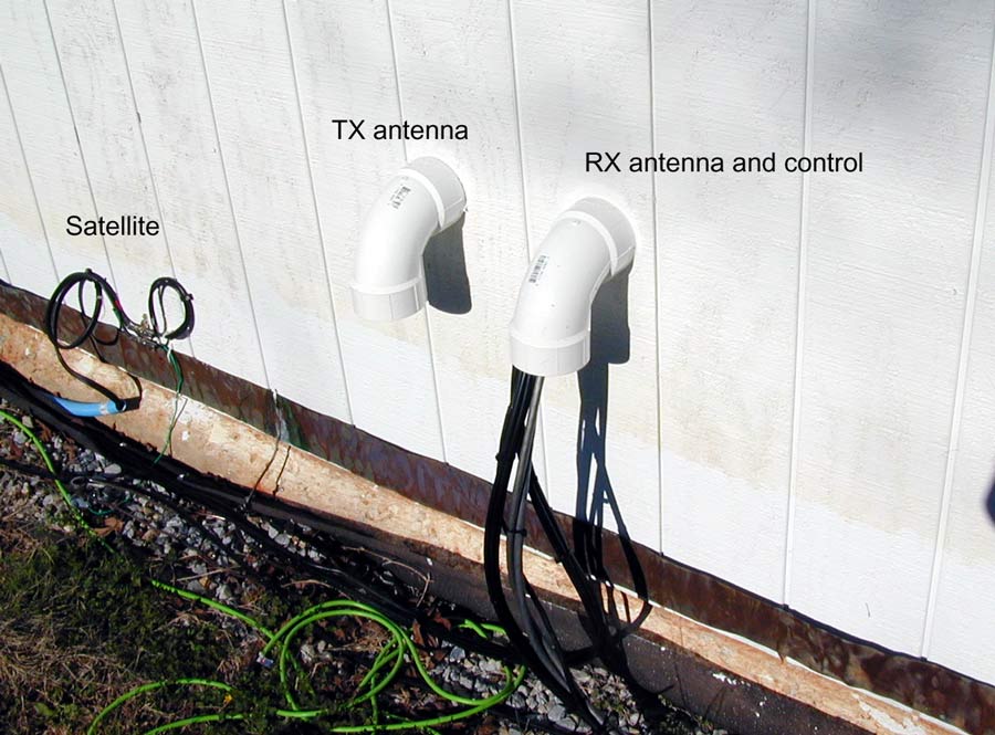
Real-world Measurements (leakage into a new 3000-foot long dual-shield coaxial cable) in summer 2006A separate receiving antenna and receiver can be used to find new multipliers while making contacts on the main radio. A second radio also can be used for two-transmitter interleaved operation on one band, provided one transmitter is allowed active at any instant of time. The purpose of this test was to see if cable shield leakage of the transmitted signal would exceed signal level picked up by Beverages or other antennas. The goal of this was to test transmitter signal ingress into the receiver's feed line and shack wiring, comparing the level from unwanted cable and wiring ingress to levels from the same transmitter into distant receive antennas. This data should also be useful in other applications, or just to illustrate the amount of ingress through this type of common, inexpensive, coaxial cable. This line is CommScope dual-shield F11 (roughly RG-11 size) cable. It consists of a single 100% foil shield with a single 60% coverage aluminum braid overlay. This is a flooded cable for direct burial, with snap-and-seal connectors.
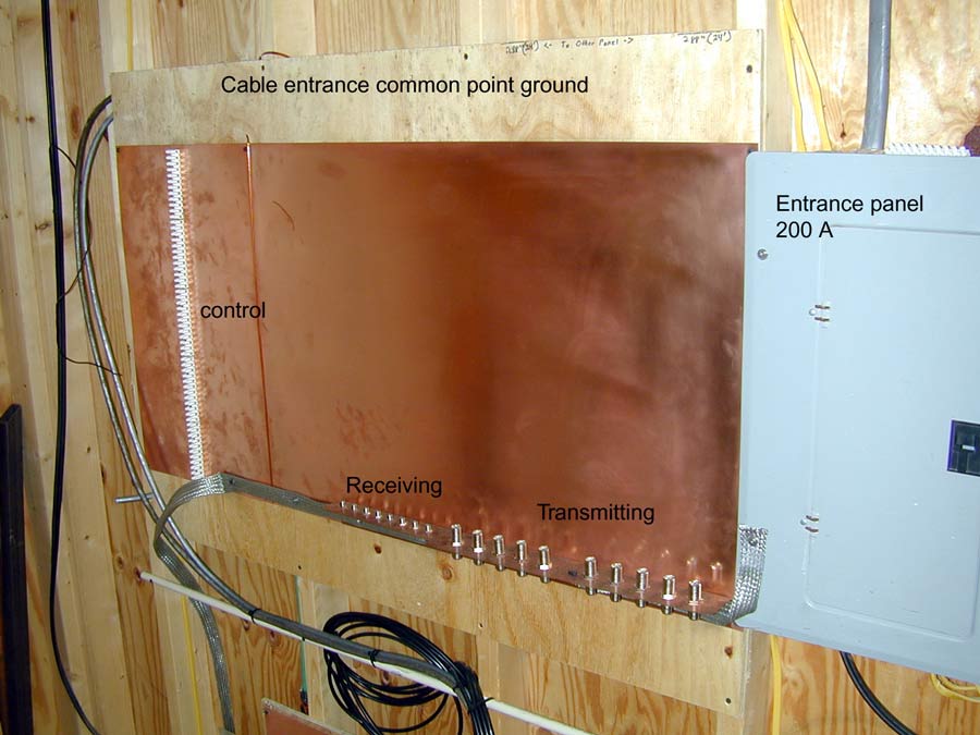
Building Entrance (old pictures)
Building Entrance Panel
Test Conditions 200 watts transmitter power. Cable terminated in 75 ohms. Signal levels are measured at receiver. Antennas used were my most distant beverage antenna group approximately 2500 feet (one half mile) from my transmitting antennas. "dBm" values below for RX antenna dBm are the values with actual transmission line losses included. 160 Meters
80 Meters
There are only two cases where signal ingress can exceed signal level from the beverages that are loacted one half mile away. Both cases are where a low dipole is mounted right above and parallel to the feed line. In these cases, the feed lines from the low dipole test antennas also paralleled the F11 receiving antenna feed line for at least 200 feet in the same bundle. 160 Meters
80 Meters
Conclusion Even with Beverages 1/2 mile from the transmitter, there are very few cases where signal ingress into the coax exceeds the signal level from the Beverages. The only cases of failure were when low dipoles parallel to the feed line were excited and compared to a Beverage with a deep null towards the transmitting antenna. This data assumes good coaxial connections. Common mode chokes were not used in this test. Certainly for any beverage installation closer than 1/2 mile to transmitting antennas feed line ingress will not be a problem. All of the signal will be from the receiving antennas and not leakage through the coax shield.
|