High power tubes should never be fused on the control grids. The reason is quite simple, any leakage current will offset contact potential bias.
A San Carlos, CA Eimac applications engineer
pushed manufacturers to us ea circuit he called super cathode drive. He wrongly
claimed the circuit would add negative feedback. This was not an Eimac
suggestion and virtually all of the staff disagreed with him. This was something
he personally promoted.
When I worked for Heathkit and Ameritron, I received
several calls from him trying to get me to float the grids off chassis. I made
IMD and stability measurements and did circuit analysis. There was never an
advantage to floating grids, and there was generally a few disadvantages.
We were scheduled to remove the grid chokes and directly ground the grids in a
revision of the SB220 series (tentatively called the Warrior II). Unfortunately
Heathkit moved out of the amateur market before that amplifier reached
production.
There was one Ameritron amplifier where I added
grid resistors in an attempt to better balance tubes. These resistors were
not intended to be fuses!
The resistors were to balance grid current better between tubes as the tubes
aged and lost emission. This was the AL811H amplifier.
Unfortunately, despite my best efforts, these resistors would fail in hard tube
anode flashovers or if the tube "leaked". These grid resistors offered a very
small balance improvement, but they put the exciter at increased risk of damage
from an amplifier tube failure. When I evaluated the positive results against
the potential cost, adding the resistors was clearly a mistake. Consequentially,
these resistors should be immediately removed from early AL811H amplifier and
the grids should be directly grounded.
I also suggest the grids in
amplifiers like the Kenwood TL-922, SB-220 series including the SB 221 and HL
series, and other amplifiers be directly grounded with the shortest widest
ground lead to chassis.
Some articles claim the grid resistor or chokes act as fuses or, even worse, were installed as fuses. They claim when the resistors or chokes blow open from a tube fault, they act as fuses and allow the tube to self bias off.
Such claims are ridiculous. Let's explore what
contact bias or self bias is, and why it does not work in high power or
defective tubes.
There are two forms of self bias on a control grid:
Note: Grid leak bias is often confused with contact potential bias, but the operation and applications behind them are totally different.
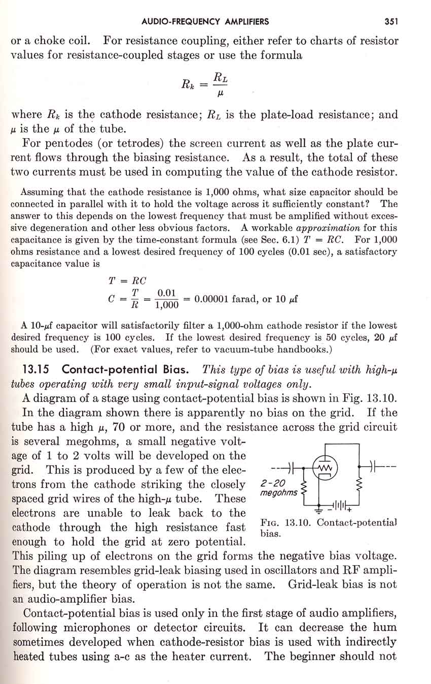
Contact potential bias is formed by space charge near the hot cathode of a tube. When electron emitters are heated electrons boil off. They collect in a cloud around the cathode. This cloud supplies all the charges available for normal operation of the tube.
Because the control grid is in the cathode cloud, a few electrons will land on the grid. If the grid has high enough resistance to ground it can develop a small negative potential (excess electron charge) of a few volts. Suitable resistances are in the order of several megohms. This is a very unreliable source of bias. Contact potential bias is useful only in very small low voltage tubes, and it is even unreliable in them if the tube is less than perfect.
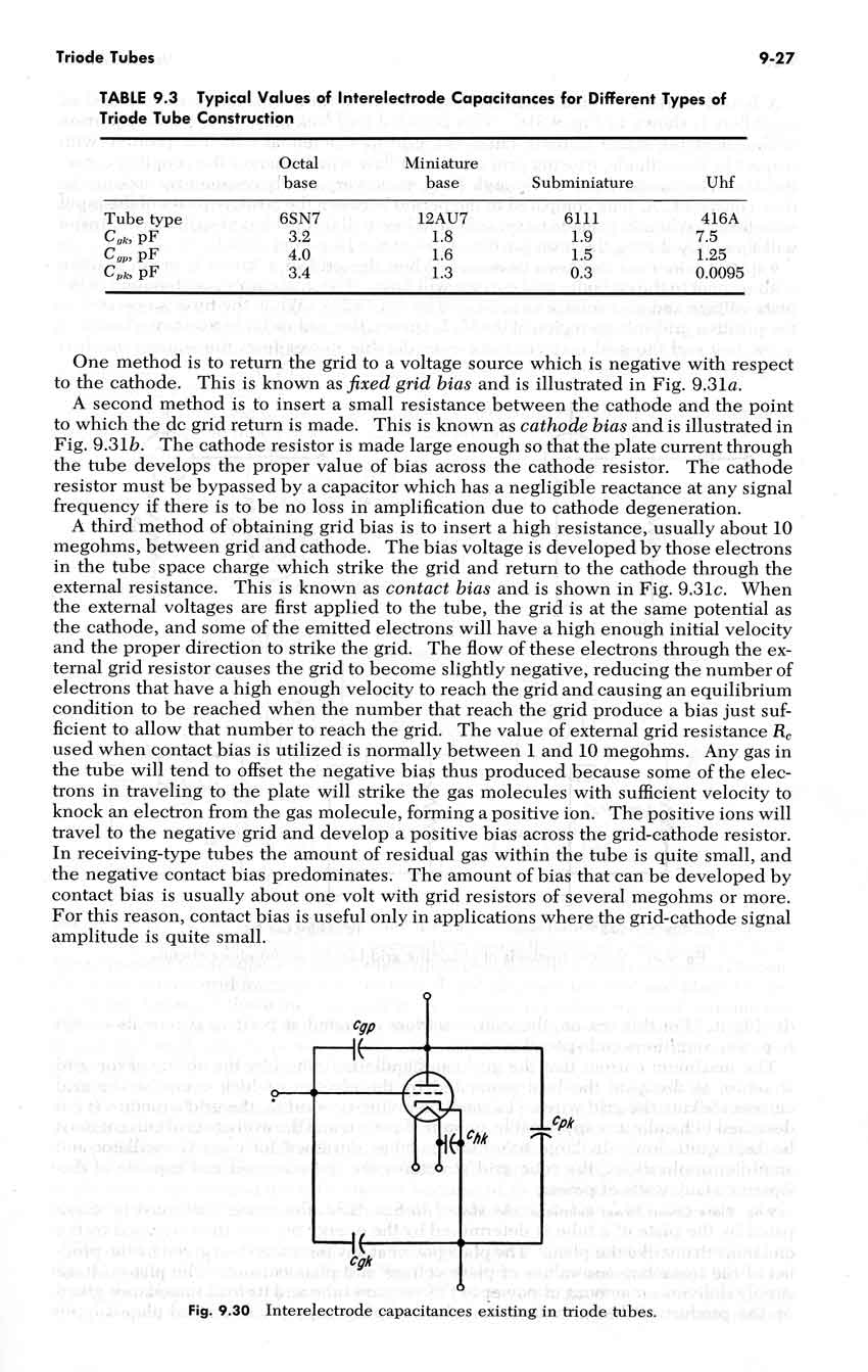
Grid leak bias is developed when a series resistance, with a suitable shunting energy storage capacitance, is placed between a control grid and the dc return path to the cathode. When the grid is driven positive current flows to the cathode. This current causes a voltage drop across a modest value resistance, and the resulting voltage drop charges a leak capacitor. The capacitor charges with a negative potential towards the grid and a positive potential towards the signal source. After many RF cycles of rectified grid current, the grid leak storage capacitor will charge to a reasonably stable voltage. Of course if grid drive is changed, the capacitor moves to a new voltage level. Bias voltage is proportional to grid current and the value of series leak resistance.
Grid leak bias is commonly used in class C amplifiers or self-excited oscillators. It is generally just a portion of total bias. It is undesirable in linear amplifiers because it encourages gain compression, although very small levels of grid leak bias can be used to equalize grid current in parallel tubes.
A few people claim grid leak bias or contact bias can be used to place a tube into anode current cutoff during a fault condition. The thought is, by placing a fuse in series with the control grid to the chassis, the open fuse will act like an infinite resistance leak or contact potential bias source and safely cut anode current off.
(also see vacuum tube failures and Fault Protection)
Destructive fault current comes from two sources:
Grids, regardless of fault type, should never be floated. This is because:
Note: This is true for screen grids also. It does not just apply to control grids. Screen grids, just like control grids, must have a reasonably low dc impedance to ground to prevent destructive runaway from a positive grid.
One participant in the Amps Reflector is convinced grid leak and contact potential bias are the same. He uses that as justification that a grid fuse is OK, since grid leak bias is OK.
Here is the unedited text from two peer-reviewed engineering textbooks that deal with vacuum tube amplifier system designs:
The text above goes on to caution beginners to NOT use or rely on contact potential bias in higher power tubes, since contact potential bias is generally unreliable and only works in special cases.
Clearly the peer reviewed engineering textbook above (used in my EE classes at Toledo University in the late 60's) states contact bias and grid leak bias are different. Grid leak bias comes from intentional grid current caused by grid drive from a signal source. Contact potential bias comes from random electrons collecting on the grid.
Text below comes from Giacoletto's Electronics Designers Handbook. This engineering book was a standard reference used in sophisticated vacuum tube system design, and was considered as one of the very best available by vacuum tube equipment engineers.
In the following text, Giacoletto separates bias into four distinct classes:
Notice Giocoletto, as in the earlier text by Shrader, makes a clear distinction between contact potential bias and grid leak bias. Dr. Giocoletto, like Shrader, cautions against high power use of high resistance grid paths. As a matter of fact Giocoletto specifically cautions about free ions, and he clearly states high grid resistance values are useful in receiving tubes only! You can find that statement near the end of Giocoletto's text.
It has also be suggested that Terman somehow supported the idea of open grids (high or infinite grid resistance). Terman actually claims the opposite. Here is what Terman actually says:
Hopefully this page will dissuade people from following the very bad advice to ever use grid fuses. We should always ground the control grids, employ fast electronic current limiters for soft faults, and use HV anode path fault limiting to protect against hard faults. We should never use protection systems intended to float a grid, either screen or control grid, in a transmitting tube!