Reason for PCV Systems
Internal combustion engines always produce crankcase fumes. Crankcase fumes primarily come from combustion byproducts leaking past rings. Secondarily, they come from other smaller-area lower-pressure leakage paths, such as leakage through valve guides or gasket leakage. Crankcase fumes are rich in acidic, dirty, combustion byproducts. These combustion byproducts, or fumes, are not good for engines. They prematurely contaminate motor oil. Crankcase fumes also condense into a hard varnish, coating parts inside the engine with a hard, dark, coating.
Keeping combustion byproducts (crankcase fumes) out of the crankcase greatly extends oil and engine life. Engine oil remains cleaner longer, and less varnish forms inside the engine.
It is impossible to increase ring and valve stem sealing enough to prevent combustion leakage into the crankcase and valve cover system. The only removal option is to displace fumes with fresh, clean, air. We call this crankcase ventilation. In modern engines, crankcase ventilation is almost always accomplished by pulling vacuum at one end of the crankcase. At the other end of the crankcase system, away from the vacuum source, the ventilation system allows clean filtered air in. The clean, filtered, air replaces the harmful fumes as the harmful fumes are drawn into the vacuum source.
It is important to replace crankcase fumes with clean air. Some supercharger kits like my original Vortech kit, and many other high performance modifications, allow unfiltered air to enter the crankcase. Worse yet, some systems completely remove vacuum-forced ventilation, allowing harmful, corrosive, byproducts to collect in the oil, valve covers, lifter galley, and crankcase. When this happens, engine life deteriorates. Engine internals can even become coated with a hard ugly varnish.
History of PCV Systems
Road Draft PCV Systems
PCV systems started years ago with road draft systems. In a road draft system, a tube from the upper engine area hangs down near the road. Air moving across the open tube end draws fumes out of the crankcase. That air is replaced by fresh air, typically brought in through coarsely-filtered valve covers 'breathers". In the 50's and 60's, it wasn't unusual to see oil-burning cars driving along, merrily streaming blue smoke out their below-car breather tubes. They would often have as much bluish-white smoke drifting out from their draft tubes as was streaming out their tailpipes.
Draft tube PCV systems required the vehicle be in motion, and still provided very limited air exchange. The result of such poor air exchange was rapid oil contamination and build-up of hard brownish-colored varnish on engine internals. It was fortunate when a road-draft PCV system car lasted 50,000 miles without burning oil, and most older engines (even with regular oil changes) had varnish inside.
Modern PCV Systems
The modern PCV system is a "winning system". The PCV system does not decrease horsepower or economy, while it keeps the environment, engine internal parts, and engine oil clean. The PCV system is very reliable, often lasting a hundred thousand miles or more without maintenance. The only parts to fail are the PCV check valve, hoses, and grommets.
Modern systems commonly use engine vacuum to draw contaminated air into the intake system. These byproducts, rich in hydrocarbons, are mixed with and burned with the regular air and fuel. The typical American V8 evacuation path is out through a one-way PCV valve at the lifter galley rear. The check valve prevents air-gasoline fumes from back-flowing into the crankcase when the engine is stopped, and the valve also acts as a flame arrestor or "backstop" in the event of a backfire. The check valve is usually a small steel ball in a housing, with gravity often forming the "closing spring". This check ball does not regulate pressure, it just blocks any reverse flow.
Gasses (hopefully no oil) are drawn out of the engine through the PCV valve by intake manifold vacuum. This causes a vacuum in the entire crankcase area, including valve covers. To replace gasses lost through the vacuuming, clean filtered air is drawn into the engine through the valve covers. This air normally comes from the regular carburetor or fuel injection system air filter. The regular air filter is a very high quality air filter, much better than older standard breather filters with their coarsely-woven metallic fiber filters used in road draft systems.
Since PCV systems usually depend on manifold vacuum, supercharged or turbocharged engines create a unique problem. In supercharged or turbocharged engines, the intake manifold operates at positive pressure during open throttle conditions. When pressurized or under boost, the intake tries to force air backwards into the crankcase. Compounding the problem, boosted engines produce more ring, gasket, and seal blow-by. All of this works to build crankcase pressure. This can push oil out of engine seals or tubes.
Many modern racers use a variation of the old road draft system, using exhaust collector vacuum to pull air out of the engine. Most of these systems don't even provide a filtered air inlet, so they are essentially nothing more than a crankcase pressure vent. Without a clean air inlet, they are one step down from old road-draft PCV systems.
Drag Racing PCV Systems
Racers sometimes use a tap into the side of a header collector to pull a vacuum. This vacuum would be similar to a sprayer siphon system, where a large volume of cross-flowing liquid pulls a small amount of liquid through a siphon tube. Certain paint guns use the same principle, where a cross-flowing air through a venturi draws paint up into the air stream. Carburetors function in a similar manner.
In tests here, little vacuum could be created. The vacuum was so low that any backpressure easily overcame the draft. With 500 CFM side draft flow at 0" SP in a mocked up 3" collector system, less than 2" negative Hg/in vacuum was created. This was with optimum hole sizes, siphon depth, and siphon tube angle. There was insignificant vacuum at low exhaust flow rates..
Also, as a general rule, these systems lack a clean air inlet. Even the crude road draft systems of the 1950's and earlier had filtered air crankcase inlets. Without a clean air inlet, crankcase contaminants are not purged.
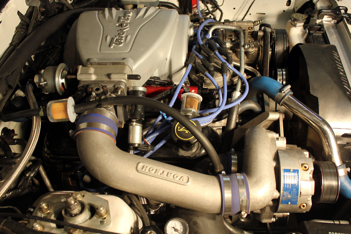
My PCV System for Supercharged 363 Ford Engine
I mostly drive my supercharged Mustang on the street. To keep oil clean and moisture-free, maximizing engine life, I wanted a modern PCV system. I not only planned a PCV system that works, I also learned what did not work for me!
PCV System Design Background
A typical non-boosted (no supercharger or turbo charger) PCV system always has some vacuum on the intake manifold plenum. A restricted portion of intake manifold vacuum, which often runs -15Hg to -20 Hg, is used to draw engine crankcase air out of the crankcase. The manifold vacuum pulls crankcase fumes out of the crankcase through a check valve. Clean filtered air flows into the crankcase, generally through the valve cover or valve covers. This fresh air prevents fumes and moisture from contaminating oil and damaging internal parts. When an engine has boost, or if an engine has worn piston rings, the crankcase tends to pressurize. This crankcase pressure must be vented or oil can blow out seals. Venting crankcase pressure, while still allowing non-boost vacuum to pull clean air into the crankcase, requires a little planning. (It took me a while to get this right.)
Some car builders use vacuum pumps to pull a vacuum, but I didn't want to do that. A vacuum pump can be expensive, requires wiring, and it also takes up space. A vacuum pump decreases system reliability, and if rings are not sealing or a gasket is bad, a pump system might not keep up with crankcase pressurize under open throttle conditions.
I wanted to purge crankcase gasses with "free" engine vacuum, while venting any positive crankcase pressure to air without restriction whenever positive crankcase pressure appears. My first try used inexpensive vacuum check valves, one or two inexpensive plastic Wal-Mart Fram fuel filters, and some standard vacuum hoses and fittings. The only machine work was adding a single hole to an unvented valve cover, and tapping the hole for a standard 3/8 inch barbed hose fitting.
My Initial Experiment
Someone described, in a conversation on a Mustang Corral forum, venting his PCV system into his supercharger inlet air. That seemed reasonable to me, because the supercharger's inlet pipe is always at some vacuum.
I decided to try that system.
This simple system, suggested on the Corral, used blower inlet vacuum to draw from the PCV valve. Filtered air went into the normal valve cover vent location through a small fuel filter that was open to the air. The fuel filter cleans the air into the valve cover, and catches oil going out.
Using a negative air inlet pressure point, such as the supercharger inlet, sounded good at first. On my car this method had two very significant problems:
1.) At low speeds or idle, there is very little vacuum at the supercharger inlet. I measured less than -0.5" Hg pressure at my supercharger inlet at cruise, and even less at idle. This connection point did not have enough vacuum to purge crankcase gasses at slow speeds or idle.
2.) At open throttle, crankcase pressure can push oil out the vent line into the supercharger inlet. That's bad, because oil lowers fuel octane. Oil in the intake system makes a mess and, in sufficient quantity, can actually hurt the engine.
After running this system for a few hundred miles, my SC inlet was wet with oil. I decided to not use this system.
First Solution Experiment
(This might work in some systems. It did not work long term in mine. )
I decided to use fuel filters to filter air. Fuel filters are cheap, and have very fine filtering elements. They also fit vacuum hoses and are easy to mount. Clear filters are readily available, allowing visual inspection for water, oil, or dirt. The downside is, if an engine has blow-by, fuel filters will very quickly load up with oil. Since a fuel filter is very fine filtering, oil contamination will significantly reduce air flow through the filter. Watching the filters for oil contamination is a necessary part of maintenance, and the clear plastic fuel filters make that job easy.
I planned on an oil separator on the outlet lines to catch any oil prior to the bi-directional inlet/outlet filter. This also turned out to not work well over time. These small fuel filters plug too easily with oil, and require constant cleaning with gasoline or solvents to restore operation. I had to wash them out with gasoline or some solvent regularly.
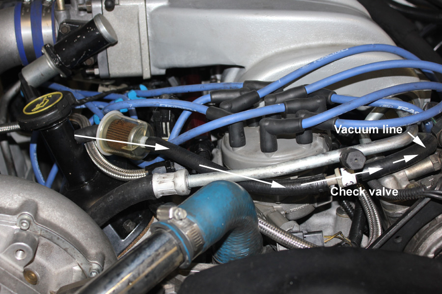
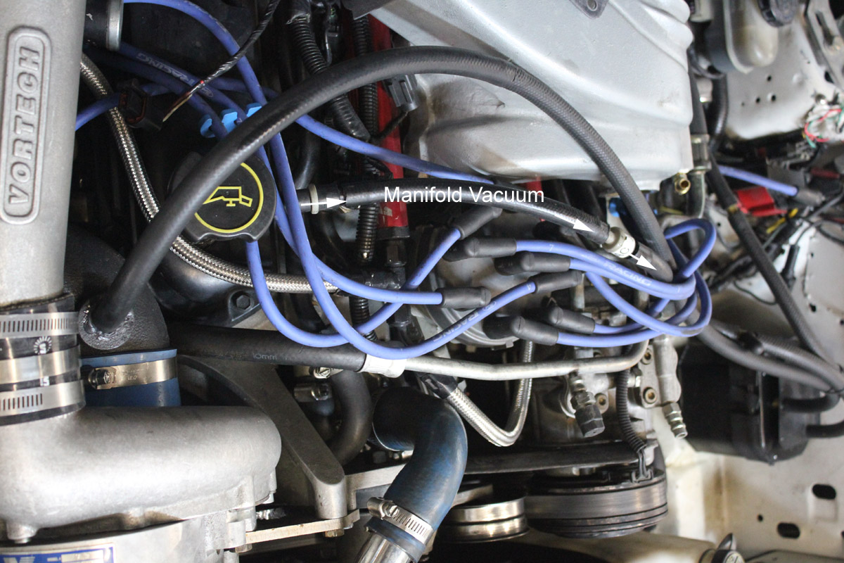
In the picture below, the vacuum line comes from the TFS intake plenum. The plenum pressure in my 363 cu in engine ranges from -25"Hg to +15" Hg under boost. A check valve allows PCV system airflow only in one direction, with crankcase air drawn out of the right side valve cover near number one cylinder to the intake plenum. The filter by the valve cover is optional, and I eventually replaced it with a second check valve. I used that filter mostly because it was already hanging there, I wanted some intentional vacuum restriction, and I wanted to see how much oil comes out that way under non-boosted conditions. I'm going to try a second, redundant, check valve located where the filter is.
If vacuum isn't restricted a little, and if the oil fill cap is opened, engine idle will be affected. I was initially worried about the unmetered air, but my concern turned out to be unfounded. Airflow through the crankcase is so small compared to metered air through the normal path to the MAF that the unmetered air turns out to be of no concern at all.
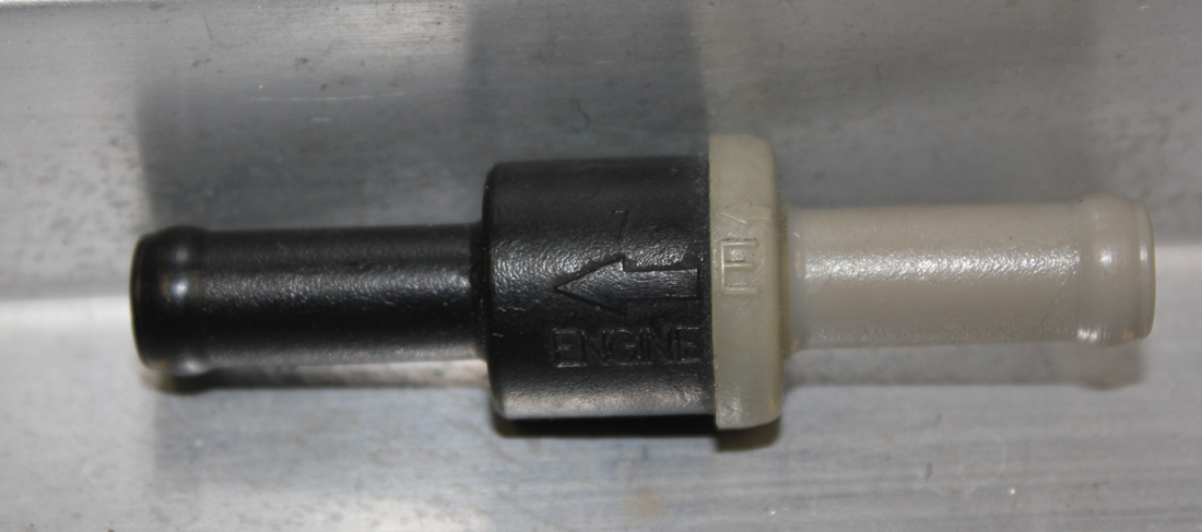
I found two different types of check valves at the local junk yard. They were used on power brake systems in little foreign trucks and cars. I think they were Toyotas and Nissans (they all look alike to me). In the foreign cars and trucks, these check valves isolate the power brake vacuum reservoir from the engine vacuum source. American cars have them, but they are normally integrated as the hose fitting on the power brake booster canister. The foreign car and truck valves are double-ended with hose fittings. This makes them ideal. You should be able to blow through the correct part in just one direction, as indicated by the arrows. I bought ten of these for $5 at a U-pull-it yard.
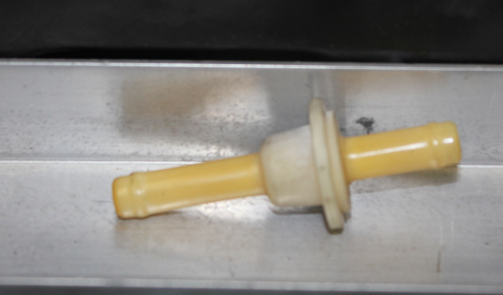
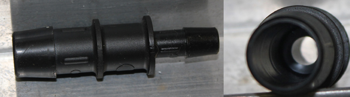
One word of caution! Do not use a normal PCV valve at the rear of the intake manifold. To get proper crankcase (lifter galley) airflow, use a non-directional coupling. Use an open adaptor that fits the PCV grommet, like the fitting pictured below. You should be able to see right through the proper PCV valve substitute:
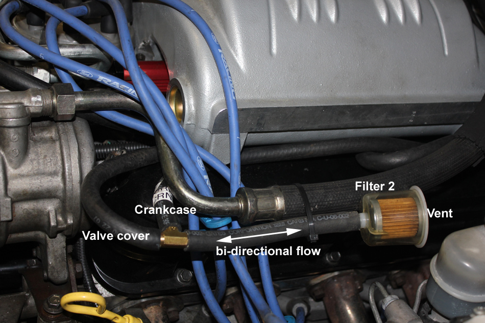
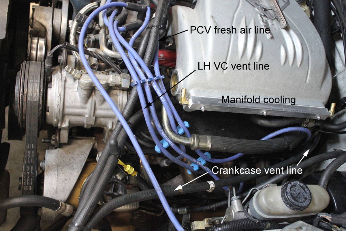
The picture below shows the bidirectional outlet and inlet system. This outlet sums both the VC vent and intake vent through a T connector. It has to flow freely in both directions. This system connects to the crankcase vent (intake manifold PCV valve grommet) and the left side valve cover. The fuel filter is critical, since it cleans crankcase inlet air. If your engine blows a lot of oil, you will probably want to use an oil separator after the T and before before the filter. So far, my engine does not need one. I haven't found any oil in this filter, even after runs at 15 lbs of boost.
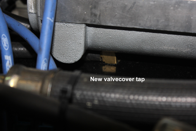
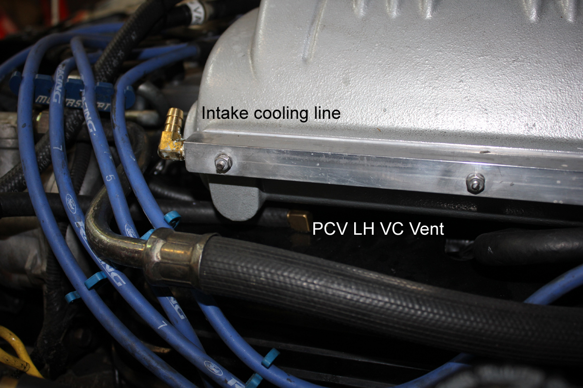
I added this valve cover tap to be sure clean air entered the valve cover. I placed the tap between the front two cylinders, where rocker arm oil would not splash and where there was maximum clearance. It is a standard brass 90-degree barbed hose fitting for 7/16" hose. Even though this fitting is located in a clear spot between cylinders 5 and 6, I shortened the pipe thread end so the fitting thread protrudes less than 1/4 inch inside the valve cover. The vent can be run to the SC air inlet, through an oil separator if you are blowing oil. If your engine does blow oil, you will want to separate the oil and air BEFORE any filters.
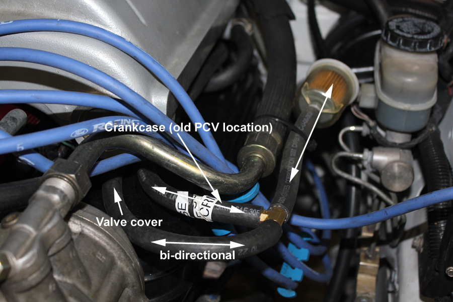
Front view of atmosphere vent side of PCV system, below:
Keeping the gas filters clean was a real nuisance. I also did not like the small amount of oil pulled into the intake system over time.
Final Solution
After a few months of running, my system evolved into this one. My manifold vacuum comes through two check valves (to prevent ever accidentally pressurizing the valve cover). This system pulls full manifold vacuum on the right side valve cover. The manifold vacuum is pulled in the normal spot high on the oil fill tube, so the vacuum does not draw excessive oil. This is the ONLY crankcase vacuum port. The manifold vacuum line runs directly to the manifold vacuum port through foreign-car power-brake check-valves retrieved from a local junk yard.
Needing an inlet for vacuum and an outlet for boost, I allowed bi-directional airflow into and out of the crankcase at the PCV valve location and at the LH valve cover. First the valve cover:
A second inlet comes from a bidirectional fitting in the old PCV valve location. This is now crankcase air inlet and outlet:
Picture Below:
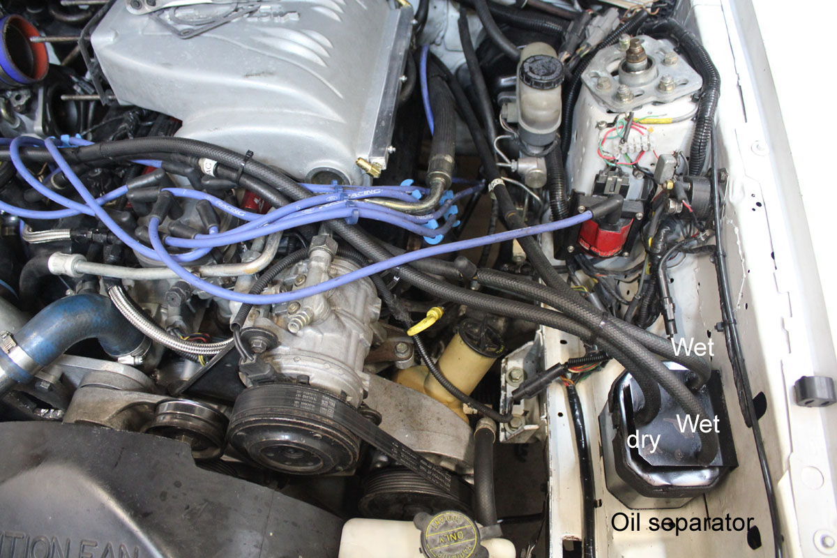
Finally, the SC air inlet is fed from a dry port (high position) on an oil separator. The LH valve cover and crankcase bi-directional flows go to the wet ports of my oil separator. Since the wet ports are at the very bottom of the canister, if any oil collects, the oil eventually draws back into the LH VC or crankcase lines by crankcase vacuum. The dry port goes to the filtered air at the SC inlet. The dry port is a barbed fitting up high on the separator can, while the wet ports have siphon tubes extending below baffles to the very bottom of the catch can. This is so the wet ports can suck any collected oil back into the engine.
Below...
SC inlet line is bi-directional after the oil separator (dry port) for clean air inlet and any crankcase boost pressure outlet. The SC air inlet line is not labeled, but it is the upper black hose. It goes from the SC elbow to the dry port on my oil separator.
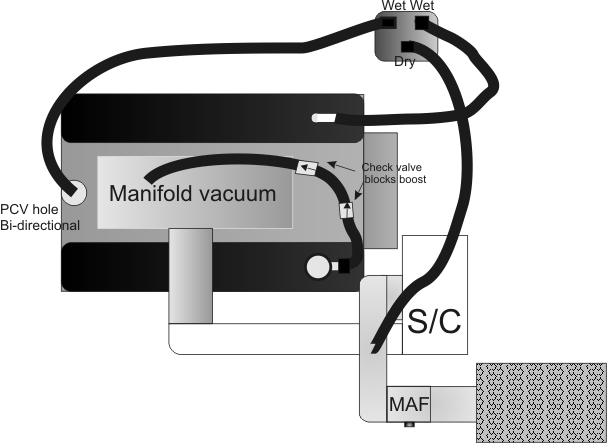
Schematic of final system:
materials © 2013 W8JI