Power transformer stress
|
Power transformer stress |
|
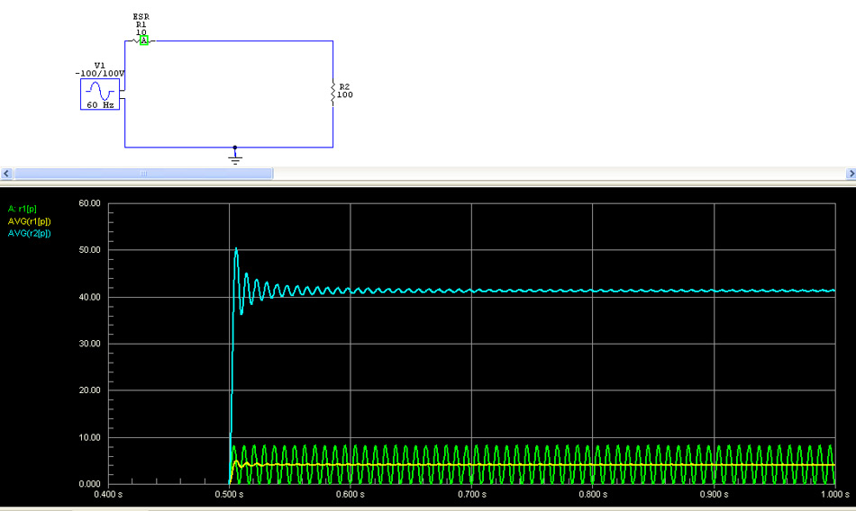
Articles and helpful comments appear everywhere about reducing heat in power transformers, or increasing transformer life, by changing from vacuum tubes to solid state rectifiers. Most of the articles and helpful suggestions make some very silly statements about heat, such as "the power transformer is weak. Changing to solid state removes 10 watts of heat from the weak Heathkit power transformer, and extends transformer life". You will find this advice everywhere for many pieces of equipment, from guitar amplifiers to amateur radio transmitters. Unfortunately, the advice is often completely opposite of the truth. We can show how this works by looking at what causes heat inside transformers. Replacement transformers are difficult to locate, and replacing damaged power transformers is often time consuming or expensive. Many of us, restorers or users of old radios and audio amplifiers in particular, would like to extend the life of power transformers in old tube style equipment. One of the ways to increase transformer life is to correct the thing causing failures. The problem is, most people guess at the cause of failures. They really don't know why something 20 to 100 years old failed, and they want to do something to not have another failure in a 20-100 year old part. Since they can only fix something they can control, they blame something they can easily do something about. This is the pattern, even though they often have no idea what caused the failure, or if the thing they are changing is actually helping. The purpose of this article is to quantify changes, and logically improve component life. Transformer FailuresTransformer failures, outside of manufacturing defects like nicked or scraped enamel insulation and poor solder joints, generally come from three sources: 1.) A transformer winding is subjected to significant heat from operation beyond transformer manufacturer's design or operational ratings, and the heat destroys otherwise adequate insulation 2.) A transformer is designed or constructed with inadequate or inferior insulation through design oversights 3.) A transformer has been subject to moisture or other external physical contaminants or stresses, and the contamination or physical stress has deteriorated insulation or internal connections Preventing or reducing failures require we understand the failure mechanism, and what effects any changes we make might have. Guessing, no matter how many radios or amplifiers we have worked on, is never a real solution! An authoritative sounding guess is really no better the guess of a totally inexperienced person, and can often be worse. People listen more to those with experience, even when they make no technical sense. An authoritative statement such as "always do this...." always sounds "expert", even when it is totally wrong. Transformer Vacuum Tube Rectifiers and Transformer Heat DamageTransformer heat comes exclusively from transformer losses, not from power passing though the transformer. This heat tends raises internal temperatures, based on how much internal heat is produced and how quickly that heat "leaks off" to the transformer outside. Naturally, a cooler transformer environment allows more internal power dissipation before insulation is damaged. The first goal should be removing heat, but we must understand what we are doing. If we don't understand what we are doing, we can easily make things worse. Losses Cause Heat, Not Pass-through PowerWhile there are several sources of loss, the predominant loss is normally in winding resistance. This is often called "copper loss". With casual thought, we might assume removing 10 watts of load power removes 10 watts of heat-stress on the transformer. This cannot be correct because the transformer loss would always have to equal load power...which we should immediately recognize as an impossible situation. Yet we find repeated statements that removing rectifier filament load removes ten watts (or some other number) of heat producing load power from the transformer. Let's consider a typical old power transformer. The primary has to supply power for all the secondary windings. The power loss in the primary is a combination of the perfect power factor load caused by the filaments and the sometimes very high power factor of a capacitor input filtering system of the high voltage supply. The most common modification is to remove a vacuum tube rectifier and substitute solid state rectifiers. Typical filament power is 2 amps at 5 volts. We are often told this removes 10 watts of power from the transformer. Since the primary is sized to handle all of the power load any heating by the rectifier filament is very low. The primary current caused by the rectifier filament load is only around 92 milliamperes. There is very little change in line current by removal of the filament load. We can reasonably estimate transformer heat by measuring the filament winding voltage change as the rectifier tube is switched to an external 5 volt supply. In the case of a National NC-303, I measured a filament voltage change from 5.15 volts under rectifier load to 5.43 volts without rectifier filament loading. This means the equivalent secondary resistance of the transformer filament winding was (5.43-5.15) / 2 = 0.14 ohms. The 0.14 ohm resistance would drop .28 volts at 2 amperes. The actual loss resistance is a little less than this...but it is close enough. We can now determine transformer internal heat caused by the rectifier filament. It is simple I^2 R heating, so the heat is 2^2*.14= 0.56 watts. Removing ten watts of filament load actually removed only .56 watts of internal transformer heat. Another way to calculate this, since the load waveform is a sine wave, is with RMS voltage difference and average current. Filament current is about 2 amperes, and RMS voltage change caused by that current was 5.43 volts no load, minus 5.15 volts full filament load, for a total of 0.28 volts drop. Since this is a resistive load with a sine wave, transformer heating will always be LESS than 0.28 * 2 = 0.56 watts. It may seem logical we can get rid of 0.56 watts of heat by removing filament load, but that really is not how it works!!! Let's look at converting to solid state rectifiers closely, and see what happens. Solid State Rectifier ConversionA little mentioned and not-well-understood factor actually INCREASES power transformer heat when a vacuum tube rectifier is replaced with solid state diode rectifiers. This heat increase occurs because a solid state rectifier is a much harder switch than a vacuum tube. A high vacuum rectifier tube switches into and out of conduction softly, over a range of many volts. A solid state rectifier diode, in stark contrast, either fully conducts with a minimal voltage drop when forward biased, or is immediately fully off when reverse biased. A vacuum tube rectifier waveform appears rather soft when in transition to conduction. The high vacuum tube can drop 20-30 volts or more, and does not supply the extremes of peak current supplied by a solid state rectifiers. Substituting a solid state rectifier for a tube rectifier always increases harmonics, and harmonics increase apparent power factor. This greatly increases heating for a given total load power. Without adding a suitable series resistance or inductance, there is a significant increase in load power factor in capacitor input supplies. (It doesn't do much to a choke input supply, since the choke input supply already has a very good power factor.) Because so little is gained by removal of rectifier filament power, transformer internal heating is often significantly increased by substitution of a high vacuum rectifier with solid state rectifiers in a capacitor input supply. We can increase transformer internal heat even when we add a voltage compensating resistance, because the resistance does not emulate the soft switching of a high vacuum rectifier. Where does most of the power transformer's heat come from?If filament loads produce little heat, where does most of the heat come from? With capacitor input supplies, most power transformer heat comes from the high apparent power factor. Short duration, but very large, load current-pulses cause much more I^2R heating of the primary and secondary windings then we would expect just from resistance and the same load current and power. Let's compare models of three loads using transformers with the same equivalent secondary resistances. A pure resistance is easy. R1 represents the transformer ESR (equivalent secondary resistance), R2 represents the load. This load is a purely resistive load like a filament winding or good full-wave choke-input filter:
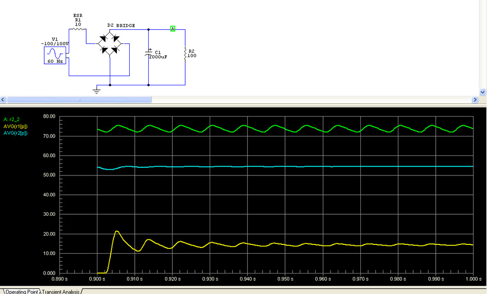
Supply voltage is 100V peak, or 70.7 volts RMS. The resulting RMS current would be 70.7/110 = .643 amps. Dissipation is I^R or .413 times the resistor value. This would give an average dissipation of 4.13 watts (yellow line) in the transformer, and 41.3 watts (blue line) in the load. A 10 ohm ESR transformer would be very efficient. Only 9.1% of total system power is lost in the power transformer with a purely resistive load of unity power factor. Same transformer with a full-wave and capacitor input filter:
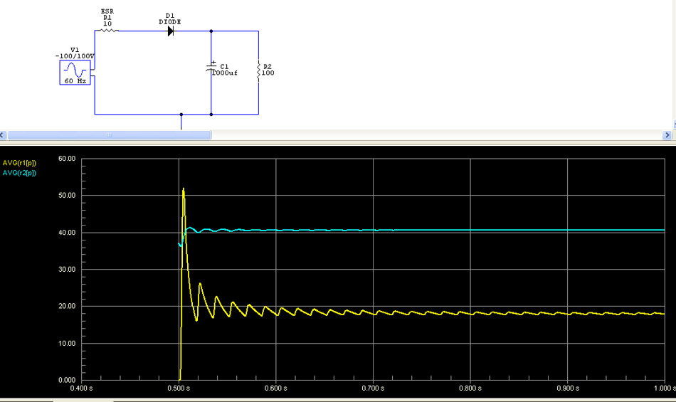
With no changes except the addition of a full wave rectifier capacitor input supply about 15 watts is lost in the transformer with 54 watts delivered to the load. Out of 69 watts total power almost 22% is lost in the transformer! Running the same load power more than doubles transformer heat when we change from a purely resistive load to a capacitor input supply! Transformer heat went from 9% of load power to 22% of load power. This is why transformers designed for resistive loads often make poor capacitor input power supply transformers. Now let's change to a half wave rectifier:
We now have 18 watts of transformer heat and 40.5 watts of load power. The transformer would dissipate around 31% of the total system power of 58.5 watts. We actually reduced load power by 25% while transformer heat increased by 20%! Comparison of this typical ESR small power transformer example for dissipation with various loads:Resistive (like a filament circuit load) or full-wave choke input filter 9.1% Capacitor input with full-wave 22% Capacitor input with half-wave 31% Clearly the largest power transformer heat savings would come from changing to a choke input supply if the equipment will tolerate the voltage being reduced to approximately 64% of voltage available with the capacitor input filter. This assumes no voltage drop in rectifiers. Voltage drop in high vacuum rectifiers would actually make the high voltage reduction less, so you may wind up with 75% or more of the original voltage. This is just one of those things we have to try in a real working system. Also, removing filament load does considerably less than we might expect. This is because tube filaments present a resistive load with perfect power factor. The transformer isn't heated nearly as much by that type of load. You might wonder why high power amplifiers use capacitor input supplies. Slightly increasing transformer size is significantly less expensive than adding a filter choke, and the overall increase in size required by a capacitor input supply results in much less weight and size increase than a filter choke would add. What we are talking about here is the possibility of reducing heat in an existing power transformer.
Some useful things to remember:
|