Also of note, VK1OD totally independent analysis. Many others have written QST with similar objections.
revised 10/11/2011 11AM est
Regretfully the October 2011 QST, on page 40, contains a fatally flawed filament voltage management article. Without question, the QST article gives life-threatening advice. The article specifically instructs readers to remove a protective cover and intentionally defeat a safety interlock by placing the reader's hand only inches from lethal voltages. The article further instructs readers to look away from their hand while high voltage is active.
There is never a reason to defeat a critical safety protection system and activate lethal voltages with protective covers removed. Anything determined with the cover removed can be more safely accomplished with the cover in place, or with power removed. This is true for all problems.
Besides safety, the article's instructions will almost certainly lead to improper equipment operation or tube life problems. Nearly all instructions in the QST article, as well as all technical information in that article, are wrong for any brand or type of amplifier. Following the article, readers are more likely to degrade emission purity and tube life than improve either.
- The article claims a 3-500Z filament is rated at 4.8 volts maximum. This is, without any question, false. Actual filament voltage range is specified as 5.0 volts nominal, plus or minus .25 volts. This means specified normal filament voltage operating range is from 4.75 volts to 5.25 volts. "4.8 volts maximum" is not true, and easily verified as false. The correct voltage information was readily available to the author and QST in tube data sheets.
- The article does not correctly correlate filament voltage to powerline voltage. Filament voltage or power transformer taps should never be adjusted without knowing minimum and maximum powerline voltage range. At the very least, knowledge of maximum powerline voltage is critical. Ideally, filament voltage should center on the nominal filament voltage and kept within allowable ranges as powerline voltage varies. Some manufacturers have already allowed for that in instructions.
- The article uses less-than-ideal metering, a 2% average-response AC meter corrected to indicate RMS, connected at the wrong place, to verify an adjustment the article claims is critical for tube life. The correct meter would be an accurate true-RMS meter.
- The article does not allow for transformer and line voltage drop under maximum power supply load and temperature. Voltage should always above minimum ratings under the lowest power line voltage condition at the highest amplifier power demand.
- The article predicts tube replacement reduction of ten times over the life of the amplifier for an attempted 0.5 volt change. The estimated improvement is unverifiable by any reliable source, and makes no sense.
Please be aware none of this is about a specific product or person. It is about the article in general, as the article may be applied to every system in the world.
Following for the article's instructions guarantees filament voltage below published minimum filament voltage (the article measures at the wrong point) at least part of the time. Your expensive tube's emission-life could be reduced, and your signal's bandwidth greatly increased, if you attempt to follow the QST article. The article and QST also needlessly place you at risk of injury or death by instructing you to remove a cover and use a rod to defeat a safety interlock. Never do this in any amplifier, no matter what brand. Advice to defeat interlocks with your hand just inches from exposed lethal voltages shows a total disregard for user welfare and safety.
This article comes with no benefit at all to readers. Following the article can actually harm the reader's equipment by decreasing tube life. It also hurts all of us sharing the bands, because reduced emission increases "splatter".
| Note: To ensure proper context, the article's exact wording is shown in "picture boxes". |
Safety Concerns First
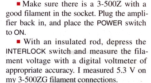
The article says:

![]()
Those are good warnings if someone absolutely must work around high voltage, but are also incomplete. It is not necessary, nor wise, to work inches from unprotected 3000 volt circuits, especially alone. The ARRL Handbook has much more complete safety guidelines, should anyone ever have no choice other than working around live high voltage circuits. Article safety falls apart here:
The ARRL Handbook, unlike the QST article, provides reasonable safety advice. The ARRL Handbook tells readers to "always follow the equipment manual" as well as many other important safety guidelines. Removing a protective cover with power connected is never safe. There is never a reason to tell people to defeat safety interlocks, while placing their hand inches from lethal voltages! Telling readers to remove a protective cover, connect the amplifier to mains, and defeat a safety interlock is an inexcusable lapse of common safety sense.
- Never activate lethal voltages with protective covers removed!
- Never defeat safety interlocks in any system, ever. Safety devices are there for a reason!
All through electronics and electrical testing and service industries, universal advice is never remove covers and disable interlocks. In some cases, defeating safety devices, or instructing others to defeat safety devices, can actually bring criminal charges. I do not believe that is the case with equipment of this type, but it shows defeating safety devices is serious. Here are Electronics and Electrical Engineering Laboratory NIST guidelines that, at least in part, the article might have considered:
high voltage safe distance off site link
local copy
Article Technical Accuracy Errors
Mistakes begin with the first sentence.
The author complains about an open filament, but Eimac's filament voltage management program is not about open filaments or reducing open-filament failures. The Eimac program is about gradual emission loss over extended operating hours in AM/FM broadcast service. You can read the actual Eimac filament voltage reduction program by clicking here, but you won't find anything in the program about the author's complaint, an open filament.
Open filaments are caused by mechanical shock, thermal shock, poor initial materials, bad solder connections in tube base pins (common with import 3-500Z tubes), or bad welds in the filament. Open filaments are primarily a function of off-on thermal cycles, mechanical shock, or poor tube assembly or filament processing.
The most common cause of open 3-500Z filaments are cold solder joints in tube base pins. The article neglects all common 3-500Z failures. The article focuses on one of the least likely 3-500Z failures, an internal open filament. It tells readers if a non-fix is applied for a non-problem the amplifier will use ten times fewer tubes over the amplifier's life!
The article then says:
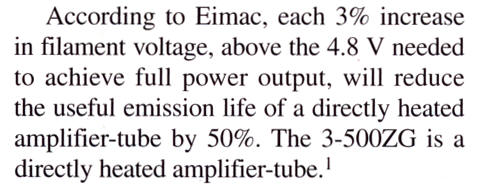
The author wrote "According to Eimac", but everything quoted came from AG6K, not Eimac. AG6K has no connection to Eimac or any tube manufacturer, and thus does not determine tube ratings. (ARRL members see this link)
Below is what Measures actually claims at http://www.somis.org/922.html We can see QST and the author extracted the above words from "bullet 3" below:
In its factory-stock form, the TL-922 has the following problems: |
Note that Measures does not link to an Eimac specification, he just tells us "According to Eimac".
Note: The light-red text boxes below this point are actually what Eimac does say, and all of this information was readily available for many years.
Also of note, the article's actual reference (AG6K) claims 1/6th life for a change from 4.8 to 5.3 volts, but the article claims 1/10th. All of this disagrees with Eimac.
Even worse, the article modifies Measures' self-created 4.8 volts "full power output voltage" to a brand-new "Eimac's maximum filament voltage rating". Neither the author nor Measures knows how much voltage is "needed" to produce full output, because neither measured it! Minimum safe operating voltage can only be determined through intermodulation measurements with SSB amplifiers, and minimum voltage varies from tube-to-tube, band-to-band, and with tube age. For the benefit of readers, I actually measured minimum filament voltage two different ways.
Minimum Filament for IMD
These measurements were made with new tubes. The target IMD was -35dB PEP 3rd order, with 3000 volts anode voltage. The target power was 850 W PEP. This power level gives 100 watts headroom for acceptable performance as the tube ages. Filament voltage is rounded to nearest 0.05 volts.
| Type | Min filament V RMS | PEP @ -35 dB IM3 |
| China | 5.25 | 800 |
| Machlett (1) | 4.8 | 850 |
| Eimac | 4.7 | 850 |
| Triton | 4.7 | 850 |
| Machlett (2) | 4.7 | 850 |
| Amperex | 4.5 | 850 |
With a variety of fresh new tubes in the same test system, we can see minimum acceptable filament voltage varies as much as 0.75 volts! It is impossible to set a minimum filament voltage without actually testing tubes. We will see, in the following text, Eimac agrees with that!
What Eimac Actually Says (not what people say they say)
This may seem obvious to some, but it needs mentioning. The first requirement, before adjusting filament voltage, is knowing filament voltage! Eimac's Filament Management paper tells potential filament management program users the following:
| Instrumentation
Are all tube elements metered in the transmitter? Elements should be metered for both voltage and current, and meters should be red-lined to define operation within safe limits. Modern transmitters may incorporate a microprocessor controlled circuit to monitor all pertinent parameters. In addition, the following controls are necessary if effective filament voltage management is to be undertaken: • Power output metering for an FM transmitter or a distortion level meter for AM equipment • Accurate filament voltage metering; an iron-vane instrument is preferred over the more common average responding RMS calibrated type but true-RMS digital meters are acceptable. • The filament voltage measurement must be made at the tube socket terminals and filament voltage control should be capable of being adjusted in 0.1 V increments. |
The author used the least preferred type of meter. The author's meter is a common 2% tolerance (on AC) average responding meter corrected to RMS. It is not the "acceptable true RMS meter"!
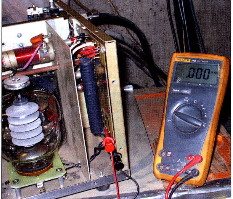
Further, in the photo above the author measures at the wrong point. Voltage at the author's measurement point is ~2% higher than voltage between tube pins. This is because of resistances in the intentionally light gauge wire, and the long socket clips. Wiring in the AL80 series is intentionally minimally sized to limit filament inrush current. This protects the tube, and should not be changed.
The author uses a 2% tolerance meter, measures at a point 2% higher than the filament-pin voltage, does not specify if he measured at minimum or maximum line voltage, and the meter is not even true RMS. In combination, all of these combine to produce a totally useless measurement technique.
The author "carefully" adjusts voltage to a useless arbitrarily-determined 4.8-volt meter value with someplace around 4% worse-case accuracy, measured with no load on the transformer. All of that is wrong. The tube filament could easily wind up more than 10% low in necessary operating voltage, which can be more harmful to life than being too high in filament voltage! It also creates unnecessary splatter or distortion.
This is a good article on how NOT to adjust voltage, because the article completely disregards everything important or critical!
Rather than saying what someone says, let's look at Eimac's words. Unedited, here is what Eimac actually publishes regarding voltage adjustment:
| When a noticeable change occurs in the output power or if the distortion level changes, the derating procedure must stop. Obviously, operation at and beyond this point is unwise since there is no margin allowed for a drop in line voltage. The voltage should be raised 0.2V above the critical voltage at which changes are observed to occur. Finally, recheck power output or distortion to see if they are acceptable at the chosen filament voltage level. Recheck again after 24 hours to determine if emission is stable and that the desired performance is maintained. If performance is not repeatable, the derating procedure must be repeated. Continuing the Program The filament voltage should be held at the properly de-rated level as long as minimum power or maximum distortion requirements are met. Filament voltage can be raised to reestablish minimum requirements as necessary. This procedure will yield results similar to those shown in the illustration (Figure 8), to achieve as much as 10% to 15% additional life extension. When it becomes necessary to start increasing the filament voltage in order to maintain the same power output, it is time to order a new tube. Filament voltage can be increased as long as the increase results in maintaining minimum level requirements. However, when a voltage increase fails to result in meeting output level requirements, filament emission must be considered inadequate and the tube should be replaced. Don’t discard it or sell it for scrap! Put it on the shelf and save it. It will serve as a good emergency spare and may come in handy some day. Also, in AM transmitters, a low-emission RF amplifier tube can be shifted to modulator use where the peak filament emission requirement is not as severe. |
The above is directly from the Eimac Filament Management program! Adjusting for minimum voltage requires measurement of distortion or some other parameter to ensure enough reserve emission and linearity. Eimac also does not claim a large life extension, you can read the text for yourself.
Actual Eimac emission data, useful if an amplifier is a successful filament voltage management candidate, appears here:
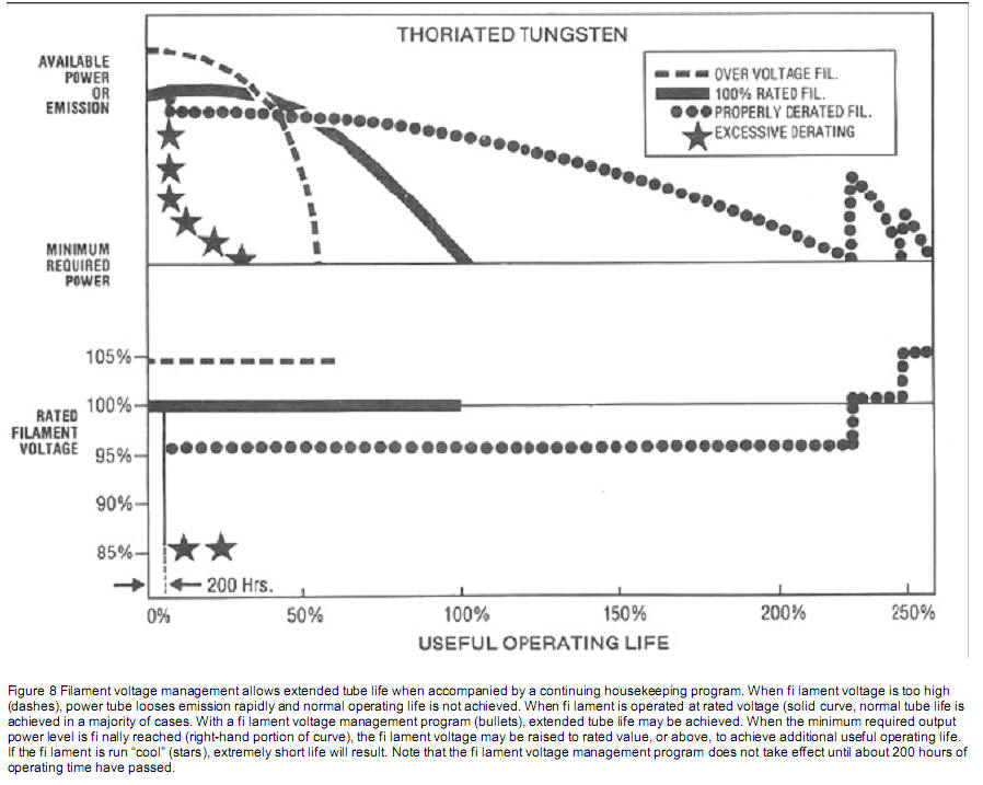
In the small text above, Eimac says "filament voltage management allows extended tube life when accompanied by a continuing housekeeping program". How many Hams are going to measure distortion weekly, and readjust voltage, or regulate their power lines?
There are many more conditions that exclude amateur use of filament management!
The above Eimac graph tells us before entering a filament management program, we should first run the tube 200 hours. For a typical Ham, that's about 6 months of operation to stabilize emission.
The Eimac graph does indicate filament emission life is dependent on voltage, but also shows too little voltage (stars) is much worse than too much voltage (dashed line). It also shows end-of-life voltage must be increased to obtain full benefits.
The graph actually tells us just less than 5% extra voltage over 100% (center of NOMINAL filament voltage range) results in about 40% reduction in life. It actually shows an ~8% increase from absolute minimum results in about 3 fold increase in emission life. This is for AM/FM broadcast use under special conditions, not amateur use! It clearly does not agree with the article.
Most important, we don't have AM/FM transmitters with regulated filaments operating 24 hours a day. It is unlikely to nearly impossible that we will ever see and life change, because amateur tubes very rarely fail from too many emission hours.
Here is what Eimac says about filament systems similar to those used in amateur amplifiers:
|
NOTE: If the filament voltage cannot be regulated to within ± 3%, the filament should always be operated at the rated nominal voltage specified on the data sheet. It should be noted that there is a danger to operating the emitter too much on the “cold” temperature side. It may become “poisoned.” A cold filament acts as a getter; that is, it attracts contaminants. When a contaminant becomes attached to the surface of the emitter, the affected area of the emitter is rendered inactive, causing loss of emission. |
Eimac warns us, if we cannot keep voltage within 3%, we should use the nominal voltage on data sheets. They further warn us filaments operated too cold (besides causing splatter or low output), will cause premature emission failure. Both Measures, and the article by repeating Measures, ignored Eimac's publications related to filament voltage.
The author's Fluke 77 digital meter is rated at 2% accuracy on AC, and is not a true-RMS reading meter.
The author also did not measure at the correct points. He measured at the choke, but there is about 0.1 volt drop between the choke and the tube pins. Filament voltage decreases more when the amplifier transformer and filament choke warms up, and when the transformer and power line is under operating load. Here is how voltage actually measures:
|
Using AL80B instruction manual
125-volt maximum line voltage settings |
|||
|
Line voltage at time of measurement |
Article test point |
Actual filament pin voltage (cold) RMS meter |
Actual filament pin voltage (hot) RMS meter |
|
124.1 |
5.32 |
5.21 |
5.15 |
If the author really set his measurement point at 4.8 volts using his meter, the tube filament could be as low as 4.5 volts or less even without normal power line variations. The author almost certainly set voltage far below allowable minimum voltage.

Eimac's application note says nothing of the sort; the author is wrong about maximum voltage. As we see below, voltage range is 4.75 to 5.25 volts. 5.25 volts is the maximum recommended Eimac voltage. Apparently no one looked at a readily available 3-500Z data sheet. We also know voltage was measured at the wrong point with the wrong type of meter.
Eimac's widely published 3-500Z voltages show a maximum voltage of 5.25 volts, not the claimed 4.8 volts maximum.
Voltage rating is, and always has been, 5.0 + 0.25 and - 0.25 volts.
Further, the article says:
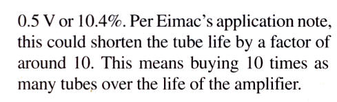
This is a problem because the article has no references to any application note. I can't find anything Eimac publishes that agrees with that, so I have no idea where that claim came from. That claims disagrees with the only article reference (Measures), and the sole article reference (Measures) disagrees with himself significantly at various places in his writings. Even if it were correct (which it isn't) the claim also assumes all tube failures are filament emission failures from long term filament operation, amplifier life will be many dozens of years, and no other failures exist.
Eimac does show, if we look at the graph for AM/FM broadcast above, emission hours until wear-out might increase about 3 times for that change. A major problem occurs because we cannot apply that data to the totally different use of amateur service with today's lower-quality tubes, especially without structured management. It appears someone just made up some numbers, and assumed every single failure would be because of emission depletion over many thousands of hours of steady use.
The AL80B transformer produces the correct high voltage when it also produces the correct filament voltage. If the filament is too high, so are anode and 12 volt buss voltages. This is a case where the author never checked with the factory, and apparently never read the manual.
If the author set voltage at his measurement point to 4.8 volts with a perfect meter, voltage at tube pins would measure about 4.6 volts with normal amplifier output power. There is 0.1 volts drop in conductors between the pins and his measurement point, and power line and transformer loading (with a good power line) causes an additional 0.1 volts drop. This is below tube ratings, and is unsafe.
It also gets worse. The author used a 2% meter that is not a true RMS meter, so the tube pin RMS voltage might be 4.5 volts or less even if line voltage never varies.
If the author adjusted his amplifier voltage during a maximum line voltage period and his power line voltage decreased 3% from increased power grid load, the tube could be operating at less than 4.35 volts.
![]()
Using the author's meter on a perfect power line, we can't be fully sure what the filament RMS voltage is, or what it will be later when we transmit or when power line voltage changes. USA power line voltage can vary as much as 10% and still be within specification, although in most cases I have measured voltage stays within a 5% range.
This article is unsafe, uses wrong voltage values as a target, promises more tube life change than is possible, probably actually decreases tube life, ignores Eimac, almost certainly increases splatter, and never even considers power line variations. It is an example of how not to optimize emission life.
The proper way to set filament voltage in the AL80B is to monitor your power line voltage for a period of time with a reasonably good meter, and determine the highest line voltage. You then follow the manual, setting transformer taps for the next voltage wiring above the maximum line voltage measured. The amplifier's high voltage meter, with the amplifier running but on standby, is useful as an alert of abnormal power line excursions. If high voltage changes outside of normal ranges for your line voltage and tap settings, verify the mains voltage has not moved significantly.
In any amplifier, you must know power line voltage extremes, and filament regulation extremes, and measure at the right point, to properly set filament voltage. It is much more reliably set if you never go over the maximum voltage! Do not set for minimum voltage, unless you know what that minimum voltage really is and you monitor distortion.
In reality, despite the article's seemingly dramatic claims, amateurs will find virtually no tube life change from doing a great deal of work and having a great deal of anxiety, and doing nothing at all. This is because the vastly predominant tube failures in amateur radio use are tube shorts, with other failures related to repeated hot and cold cycling, and tube manufacturing defects. Emission failures from filament-hour depletion, while a worry in broadcast service, are virtually unheard of in amateur radio. However, operating a tube with improperly implemented reduced filament voltage, as advocated in the article, will make it more likely the emissions from the filament will decrease over time, due to poisoning of the emissive material.