Under Construction.....
I was surprised by a lack of information about building a simple detector probe.
Let's consider a source of 100 watts and look at how to design an HF probe to rectify and detect the amplitude of an RF envelope. First we have:

100 volts would be the peak RF voltage of a 100-watt PEP transmitter into 50 ohms. RMS voltage would be 70.7 volts.
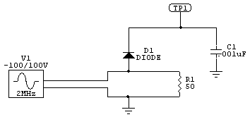
If we sampled through a diode directly we would have this:

The diode charges capacitor C1 to 100 volts minus the diode voltage drop. The diode reverse voltage is roughly twice RF peak voltage, or 200 volts. That is a high voltage to find in a low capacitance diode suitable for detecting high frequencies! A typical small signal fast diode like a 1N4148 or 1N916 is only around 75 to 100 volts PRV.
Also note we have a conduction threshold region where the detector is very non-linear. That would be down around 1 volt, depending on the diode and the current drawn from the diode. To minimize distortion we want a very high impedance load and the highest possible voltage. Otherwise we would need a more complex detector with active bias on the diode.
We also have to be sure there is a low impedance dc path through the source and load to ground for diode current. We can't always depend on that. Making a detector like this, if we want more than relative output, is not as easy as it might seem.

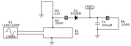
This is a 10:1 divider, so with 70.7 volts RMS we have .0637 amperes RMS divider current. This is 4.5 watts total dissipation. There is 7.07 volts across R3, and 63.63 volts across R2.
R3 dissipates about .45 watts.
Dissipation (use RMS for heat) in R2 E^2/R = 63.63^2/ 1000 = 4 watts. That is a big resistor and a good deal of heat for a non-inductive resistor. It also upsets load impedance a little bit, making SWR 1.05:1 or so.

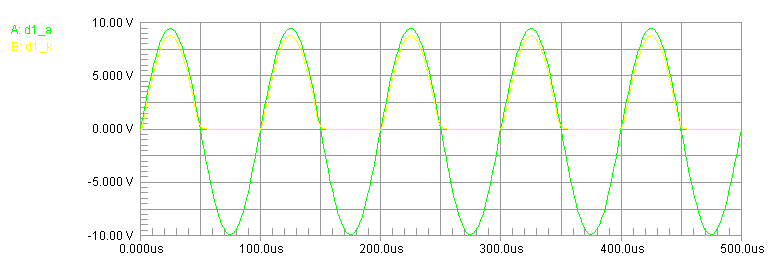
10 kHz response is good with a 2000 ohm load and .001uF filtering. We lost about 1 volt off the top, partially from diode current loading the divider and partially from diode voltage drop.