Antenna System Sales through CTR Engineering, Inc
Short verticals, while providing construction simplicity and space advantages, can present electrical problems. Let's walk through some cases.
The 43-foot vertical has become the new standard of vertical antenna heights. A typical 43-foot vertical vertical presents the following 50-ohm SWR curve. 43-ft verticals with 50-ohm feeders have three low-SWR points. SWR is:
| 1.8 MHz | >100:1 |
| 3.5 MHz | >100:1 |
| 7.0 MHz | 7:1 |
| 10.1 MHz | 23:1 |
| 14 MHz | 27:1 |
| 18.1 MHz | 2:1 |
| 21 MHz | 12.4:1 |
| 24.9 MHz | 18.4:1 |
| 28.5 MHz | 4.8:1 |
Low SWR:
| 5.8 MHz = 1.38:1 | 17.07 MHz 1.03:1 | 29.6 MHz = 1.22:1 |
Normalizing to 200-ohms will show us what it looks like through a perfect 4:1 current balun or un-un. Notice the only SWR points above 10:1 occur below 5.2 MHz. SWR is still off scale below 4 MHz :
On 80 and 160 meters, with 100 watts radiated power, RMS base voltages and currents will be:
|
Peak voltage = 6364.4 V |
Frequency = 3.5 MHz RMS base voltage = 849.9 V at -87.91 deg. Peak voltage = 1201.75 V |
160-meter Operation 80-meter Operation 43 ft Vertical
Mismatched Operation
Mismatched operation will generally be accompanied by considerable loss, with most of the stress concentrated in the matching transformer. With a feed line SWR over 100:1, insulation in the antenna will not be an issue. feed line and matching system losses will dominate.
Tuner or Matching at Antenna Top
The superior system would be top loading with a hat or "L" wire. Unless the wires are folded back when operating higher bands, some sort of trap or switching system will be necessary. Construction of high power isolating traps or switches is a significant challenge, unless losses in a poor ground or matching system limits antenna power.
Single 35 ft wire at 45 degrees.
L
| Frequency = 1.82 MHz RMS Base Voltage = 2069 V at -89.5 deg. Peak base V = 2926V (no hat voltage 6400V) Current = 5.486 A at 0.0 deg.
|
Frequency = 3.5 MHz RMS Base Voltage = 45.46 V at -28.49 deg. Peak base V = 64.3V Current = 2.503 A at 0.0 deg.
|
SWR Plot
Four 35' wires at 45-degrees
Base voltages at 100 watts radiated power with four 35-ft hat wires:
| Frequency = 1.82 MHz RMS Base Voltage = 804.6 V at -88.63 deg. Peak base V = 1138 V (no hat voltage was 6400V) Current = 5.214 A at 0.0 deg.
|
Frequency = 3.5 MHz RMS Base Voltage = 414.8 V at 83.99 deg. Peak base V = 586.53 V Current = 2.303 A at 0.0 deg. |
SWR Plot with 4-wire hat:
Base matching on 160 and 80 will produce the highest efficiency, unless some form of hat or top loading wire is used.
Voltage causes arcing and instantaneous operational failures, while current is generally a time average failure from heat. Consequentially, arcing failure voltages must be considered by instantaneous peak voltage. Heating is by long term average RMS voltage or current.
The arc distance of 5kV is about 1/2 inch for optimum dry conditions. Most "legal power" antenna tuners will only handle 2.5 kV peak or less. This means on 80-meters, a typical 1500-watt antenna tuner will allow 150-watts of equivalent radiated power before failing. When running high power, that 150-watts can be from a combination of feed line losses, ground losses, and matching network losses. It is a real limit.
The base insulator below is for a 43ft vertical that was mounted over a good ground system and fed with a good loading coil on 80-meters. The insulator failed at 700-1000 watts peak transmitter power.
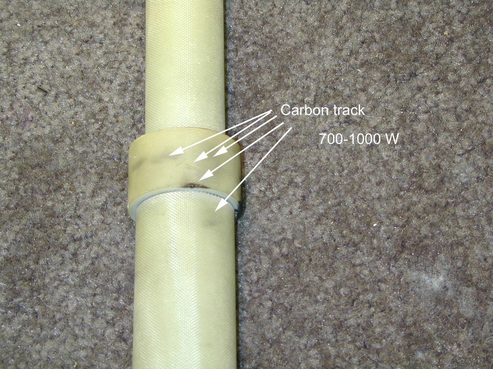
The limitation for a given radiated power on 160 and 80 meters is normally going to be insulation somewhere in the system.