Why is a tuned input necessary?
An RF power amplifier's tuned input circuit is more than just impedance matching. While reasonable impedance matching can be important for proper exciter operation, the tuned input circuit of a grounded-grid or cathode driven radio frequency power amplifier provides multiple important functions for the amplifier:
- The tuned
input system
prevents harmonics
generated in the
PA tube from
passing back to
the exciter
- This prevents false high SWR or exciter power readings, since cathode harmonics show as reflected power
- The tuned
input circuit
provides a stable
low impedance to
the cathode of the
PA tube
- This helps amplifier linearity and reduces IMD, and can improve PA efficiency
- The tuned
input circuit
matches the
cathode impedance
to the exciter
system impedance
- This lets the exciter work into a proper SWR
A tuner between the amplifier and radio, a matching circuit some distance from the cathode, or a high pass or broadband network will not do all of the above.
Harmonics
Current in the cathode shares the same path through the tube as current in the anode, with an additional current that flows in the grid-cathode path in class sub-2 amplifiers. (AB1 amplifiers have no grid current, while AB2 amplifiers have grid current.) The cathode of a vacuum tube essentially contains the same time-varying current as the anode, and if there is any grid current that additional current is also harmonic-rich current.
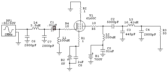
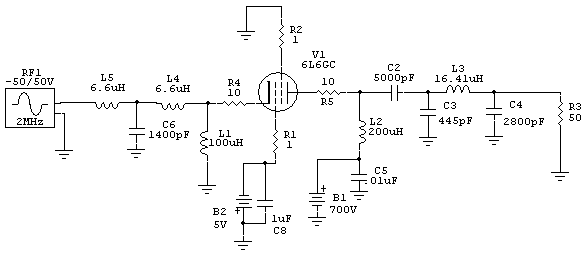
This is a spice model of a grounded grid pentode tube operating class AB2.
Drive voltage is 35 volts RMS, or 24 watts.
Output power is 112 watts.
Cathode harmonics across resistor R4:
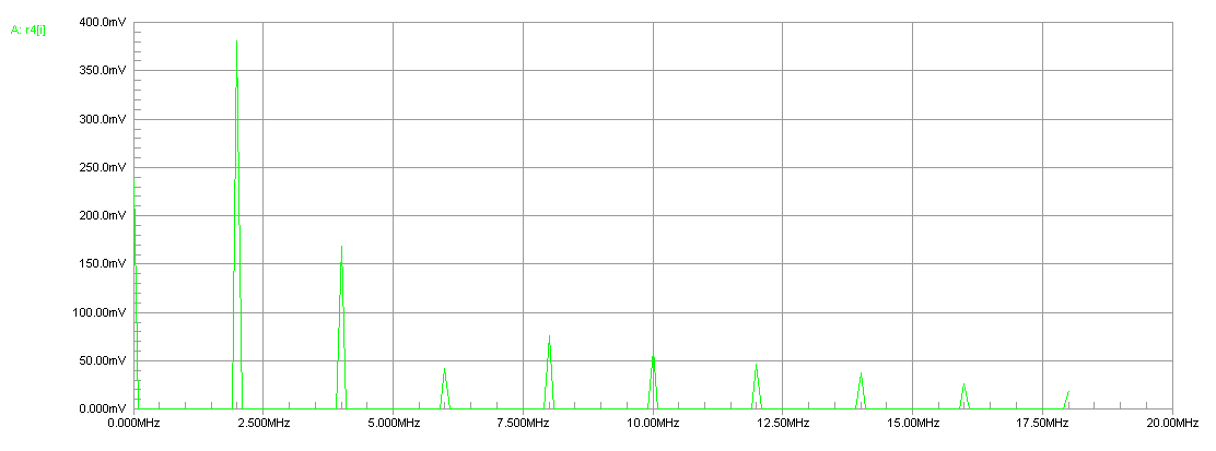
Harmonics at exciter are negligible thanks to low-pass filtering by the tuned input:
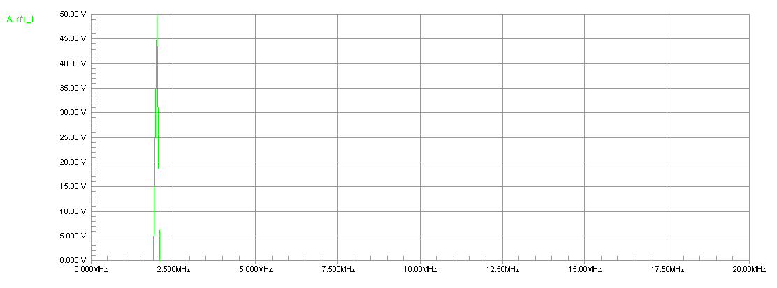
It is important to use a low-pass input matching network that presents a low impedance for harmonics at the tube cathode. This keeps cathode current transitions between conduction and non-conduction very sharp. A sharp transition into and out of conduction and reduction of cathode harmonic energy keeps efficiency high.
Type of Tuned Inputs and the Effects On Amplifier Performance
The tuned input should always be located as close to the cathode of a grounded-grid amplifier as possible. The input circuit should never be a large fraction of the wavelength away from the cathode at harmonics of the highest operating band. This probably relegates the safe distance to a few inches for an HF amplifier, although it is tube and operating class sensitive. There is also a way to work around issues, any distance will work as long as the cathode "sees" a relatively low impedance at harmonics.
I learned this lesson well when designing a pair of 3-500Z's for Heathkit. After struggling with low plate efficiency on ten meters and poor IMD performance on ten and fifteen meters, I found the problem was in the cable length between the tuned input network and the cathodes of the 3-500Z. Changing that cable from 52 ohms to 18 ohms increased efficiency from 30% to 60% on ten meters, and improved IM3 from -31 dB PEP to -38 dB PEP on fifteen meters. The reduction in cable impedance added capacitance to the tube cathodes and significantly lowered cathode impedance on harmonics. The reduced cathode harmonic impedance sharpened the transition into and out of conduction, and greatly reduced even-order harmonics in the cathode system.
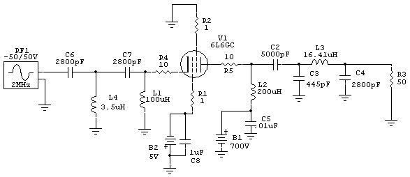
This tuned input is a high-pass "T" network. It presents a variable, but generally high, impedance to the cathode at harmonics. The harmonic frequency impedance at the cathode is greatly affected by the length of the cable between the amplifier and the exciter, and by the exciter's "reverse impedance" at harmonic frequencies.
Amplifiers using this type of input will be critical for cable length between the exciter and amplifier. This is because the length of the coax between the exciter and amplifier has a very large effect on cathode impedance on harmonics. The harmonics can also back-feed the radio, causing an apparent high SWR even though the fundamental frequency is matched!
This system is a low-pass "T" network. Even though it is a low-pass, it presents a high impedance to the tube on harmonics. Because it is a low-pass filter, cable length and exciter output port "reverse impedance" have very little effect on amplifier performance. While it sometimes works and does make the amplifier immune to changes in input cable length, it can also cause a reduction of efficiency and an increase of IMD.
This is the best system for tuned inputs. It presents a low impedance on harmonics, especially the even harmonics, at the tube cathode. This improves efficiency and IM performance, or at least eliminates the chance of problems in efficiency and IMD performance as exciters and cable lengths external to the amplifier are changed.
The input network should be installed as close to the tube as possible, with less than one foot of lead at ten meters. If the input circuit has to be installed remote from the tube, C7 can be moved to the cathode area or the coaxial line between C7 and L1 can be reduced to a very low impedance. Using a low-impedance line has the same effect as moving capacitor C7 closer to the cathode.
Input Impedance
The driving impedance of a cathode driven amplifier always varies some amount with power level and tuning. We can say the input impedance of a cathode driven stage is dynamic, with the tube's driving impedance changing with parameters like drive power and how the amplifier is loaded or tuned.
The input impedance changes dynamically because the output system is in series with the input system. The same plate current flows through both cathode and anode systems. Varying anode load impedance, because the same very same current flows through both, changes input impedance. In general the lower tube mu, the greater the effect of output tuning and power level on driving impedance. This is because a low-mu tube generally has a high driving impedance, making cathode impedance a larger percentage of anode impedance. The higher cathode impedance increases negative feedback, and increased negative feedback causes the input impedance to vary more with anode load impedance changes. The tuned input's resonance or "flywheel effect" does not stabilize this impedance variation, but additional losses brought into the cathode system by tuned input circuit components helps dilute or "swamp out" dynamic changes in driving impedance. An attenuator pad would do the same of course, but would not filter harmonics or sharpen conduction point transitions.
The dynamic cathode impedance, where cathode impedance changes with drive level, prevents us from accurately adjusting the tuned input system of a typical cathode driven amplifier at very low power. This prevents accurate use of an antenna analyzer to adjust the tuned input while using the operating PA tube as a load. The input system should always be adjusted near full output power under normal operating conditions, or with a suitable dummy load replacing the tube's dynamic impedance.
A reasonable approximation of tube input impedance, for circuit adjustment purposes, would be a small non-inductive resistor from each cathode pin to a control grid pin at each tube. This resistor should be the approximate value of the tube input resistance when driven near full power with normal tuning and loading. Filament power and HV should be off and the tubes left in place, and the input driven normally as if the amplifier was running but with a low power antenna analyzer substituting for the the normal exciter.
For various tubes the following cathode resistances are used at each tube:
| 811A, 572B | 220 ohms |
| 3-500Z | 100 ohms |
| 4-1000A | 90 ohms |
| 3-1000Z, 3CX1200 3CX800A7 |
68 ohms |
Using Tuners in Radios, or External Tuners, for Matching
- If the amplifier contains a proper low-pass tuned input, and impedance is close but not quite right for your exciter, there is nothing wrong with using an external tuner.
- If the input network is missing, or is a high-pass network, relying on an external tuner might cause IMD or efficiency problems. There is no guarantee the system will have a problem, but there is also no guarantee the system will not have a problem.
- Without a proper tuned input, system behavior will vary with the exciter type, the band being used, cable lengths, and other variables.