Full line of parts, service, and
repair by designer at CTR
Engineering, Inc
Vacuum Tube Evolution
Throughout history, to speed development and reduce tooling costs, newer tubes use tooling from older tubes. The AL811 tube is a descendent of the 812 tube. The 572B is an indirect descendent of the 811 tube.
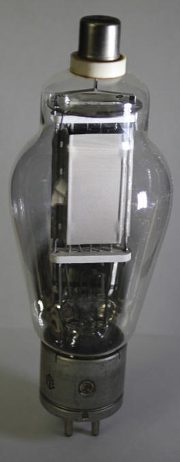
812 Tube
The 812 was a moderately low mu tube, primarily intended for grid driven modulator service. The 812 was used in some higher power WW II AM transmitters.
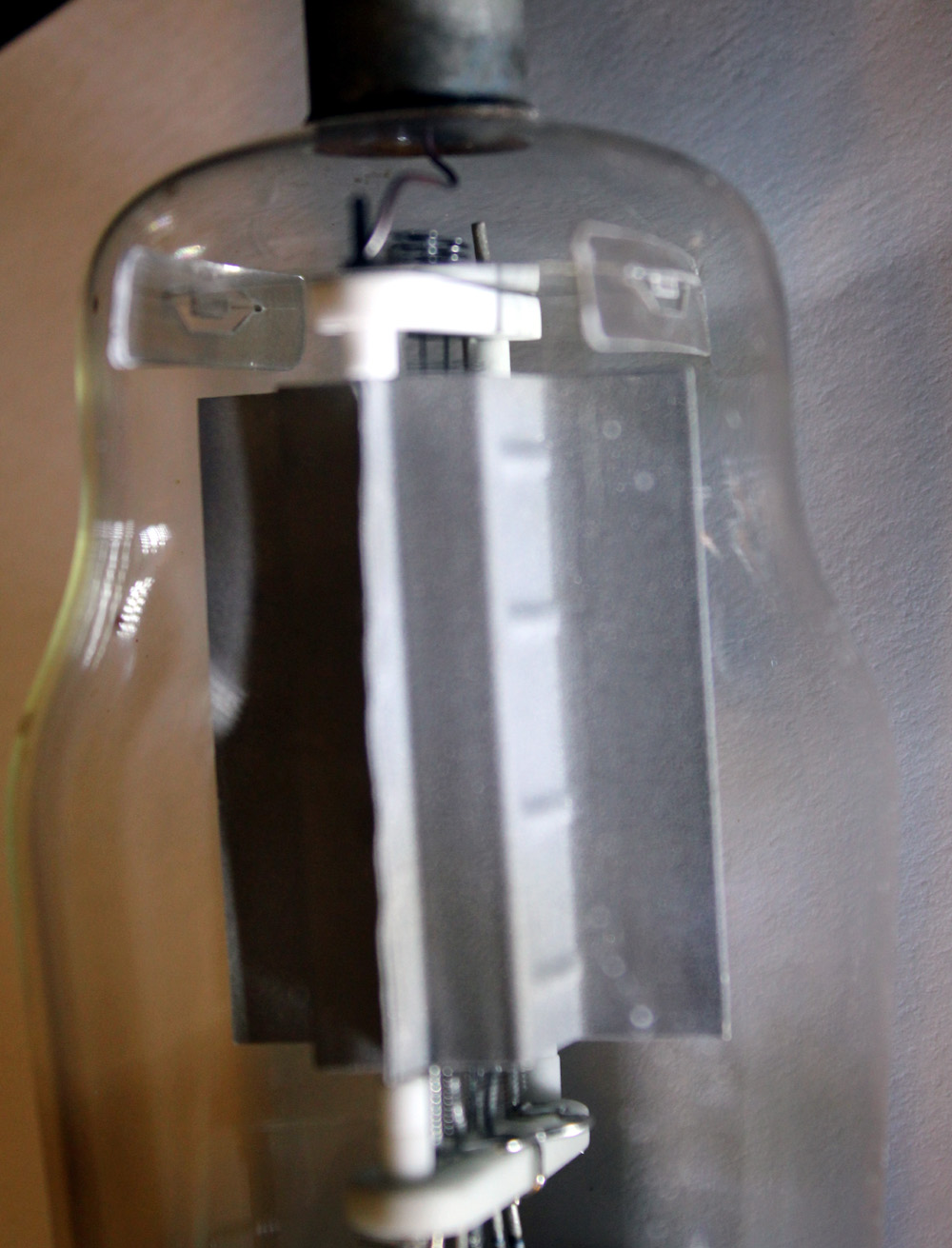
This is a GE 812 tube.
The envelope, anode, and filament are identical to the 811 tube.
Note the very wide flat gray colored area. This is the anode.
It is very thin. Because the anode is so thin, the anode heats rapidly.
The anode is damaged or destroyed by any color over dull red.
The 812 was low-mu. The 812 requires a great deal of negative grid bias voltage, in the 40-50 volt range or higher. This is because the 812 has wider spaced grid wires, so the grid wires do not shield the electrons around the filament-cathode from the anode's high positive potential.
Higher mu tubes have a denser control grid screen. The reduced wire spacing increases electric field density between grid wires. This reduces cathode emission current for a given negative grid voltage, and increases "shielding" between cathode and anode. Higher mu tubes have less anode current for a given negative grid bias, all other things being constant.
The control grid of the 812 was changed by increasing winding pitch. This made the 812 into an 811 tube.
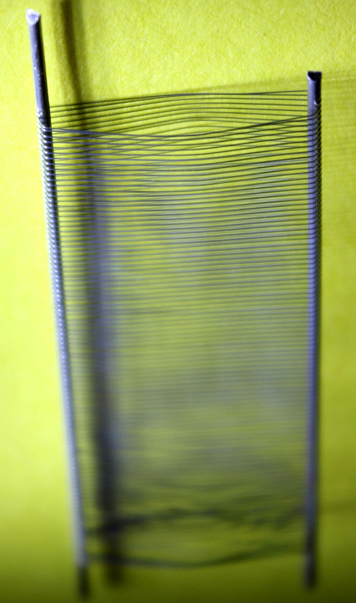
Typical 811 and 572B/T160L control grid.
This grid can be run almost to the point of incandescence without damage, although normal operation limits the grid dissipation to a much lower value. The lower operating dissipation is to avoid secondary emission from elevated grid wire temperatures, rather than avoiding grid damage or failure. (A gold plated grid would suffer permanent damage long before significant secondary emission occurs.) The real weak spots in 811 and 812 tubes were the very thin anodes. Thin anodes lack thermal mass, and suffer damage from brief overloads.
Electrons have kinetic energy. This energy heats the anode. The heating is much like a resistance, but an entirely different mechanism is at work. The dissipation formula is the same as a common resistor power formula, Pd = E*I This formula works because electron velocity is tied to E, and the number of electrons are tied to I. At every single snapshot of time, anode heating is simply E*I. We all know thinner metal heats faster than thick metal, and that thicker metal also cools slower. The physical mass of the anode averages the instantaneous heating over time to an average dissipation.
We can roughly calculate short term average dissipation as Pd = Pin - Pout, where Pin is average dc plate input power and Pout is RF output power. The actual heat, however, is caused by the instantaneous E*I product plus a small amount of heat transferred in from other tube elements and heat sources.
The 811 and 812 tube cools almost exclusively by infrared emissions. Very little heat is conducted out of the tube, or into the envelope. As a result, tube life is NOT impacted by air flow rate on the envelope. It is a waste of time to cool the envelope far below thermal limits of the glass. Cooling the envelope will not increase anode dissipation capacity, or reduce anode heat.
Because electrons striking the anode causes anode heat, the surface heating at any point is directly tied to the number of electrons striking that area. The center area of the anode was the hottest, and that is where all abused 812 and 811 anodes failed. The normal failures would appear as a shiny metal spot on the anode.
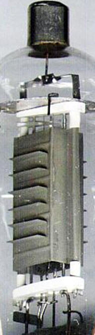
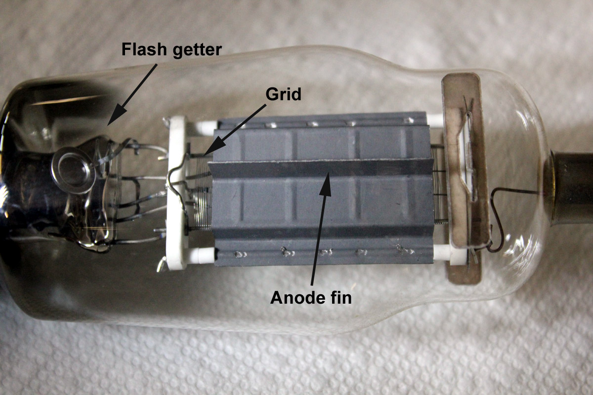
The thin 811/812 anode was improved by welding a series of U channels to the anode, normally three channels on each anode side. These U channels were welded to the anode. The U channels thicken the anode under each channel, and bridge the anode from side-to-side. The extra channels increase thermal mass in the area where electrons strike the anode, extending the thermal averaging time. The thermal averaging time of the anode tripled from the non-finned original anode. Instead of 20-30 seconds thermal averaging time for overloads, thermal averaging was extended to over one minute.
A secondary benefit to the addition of U-channel cooling fins was an increase in infrared emission area. This produced what seems like a meager 5 watt increase in ICAS dissipation, from 60 watts to 65 watts. That was a very conservative "published rating" of 811A anode dissipation. The actual working dissipation was much higher, actually 80 watts or more long term average power.
A Step Backwards Modern 811A Tubes
U-channels on the anodes of 811A and 812A tubes are expensive. To be effective the U-channel must be very flat and the U-channel has to be welded to the basic anode core. This is a costly process.
When 811A tubes appeared from offshore, they had a modified anode. The original USA 811A tubes were perfectly flat at the high-temperature high-current anode area with welded U-channels to increase thermal lag and dissipation. The import tubes eliminated the channels, and folded the anode up. The fold provides about the same infrared radiation area as the original 811A, and the import tube has the same 65-watt long-term dissipation.
Unfortunately, the new import anode greatly reduces shorter term dissipation capability. Instead of requiring 60-100 seconds of 200-watt dissipation to go beyond thermal limit like the USA finned anode "A" version, the import "A" version's folded anode thermal limits at hot spots in about 15-20 seconds at 200-watts dissipation.
Operators have to be mindful of on-time when tuning, and watch transmitting times in higher average dissipation modes.
The excellent averaging time of the increased thermal mass through old 811A anode U-channels is mostly lost in the new 811A tube. The vertical fin is now made from a single tall fold in each anode face. This system does not conduct heat out of the flat anode areas between the anode middle and anode narrow edge very well.
If you look at damaged 811A import tubes, heat failures occur around the middle flat areas. These areas would be finned in the channeled anodes, which would smooth or even the temperatures across the anode and fin surfaces.
So while the import tubes have the same "book" long-term anode dissipation of 65 watts, they have greatly reduced short-term dissipation capacity. The vertical fold anodes are 65-watt anodes, but the short term dissipation or allowable overload time is reduced to nearly the value of the early non-finned 811 or 812 tubes.
Duty Cycle of Tubes
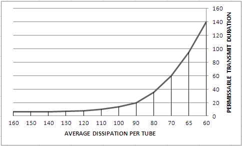
"Folded Plate" 811A tube Anode Damage vs. Permissible Transmit Time for average dissipation in any series of consecutive 20-second time periods
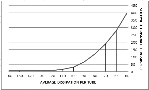
"U-Channel Plate" RCA 811A tube Anode Damage vs. Permissible Transmit Time for average dissipation in any series of consecutive 20-second time periods
New 811A tubes have inconsistent cut-off characteristics. This is similar to the Svetlana 572B behavior differences known to cause problems in Yaesu amplifiers, where tubes oscillate on standby. People blame this on higher tube mu or transconductance, but the problem really centers around cutoff bias characteristics. Tubes behave like they are lower mu for cutoff, like a semi-remote control grid used in tubes designed for AGC controlled stages.
Occasionally this causes 811amplifiers to make receiver noises, like a popping or broadband noise. This noise might also be heard from the rear panel area of the amplifier as a very faint buzzing, ticking, or clicking noise. The noise may or may not change as BAND, PLATE, and LOAD settings are changed. This noise happens only on standby. If the amplifier includes gas protection tubes on the filaments, the gas tubes may fire during the noise periods.
This problem took a while to locate, because I could not initially replicate the problem. After the problem was initially located, tubes starting arriving with different characteristics.
This problem appears to be related to the cutoff characteristics of the 811A tubes. I plotted the plate current with various bias voltages at this page 811A tubes . Tubes with sharper cutoff have the oscillation issue below. Because of tube variability, a three-tier approach is best.
There have been no reported problems when the mods below are included:
1.) Be sure your amplifier has gas clamp tubes. This protects the amplifier T/R relay and exciter if tubes have a hard arc
2.) Be sure any un-neutralized 811 amplifier has the damping resistor discussed below. This is primarily for the AL811, not the AL811H, although it may not be a bad idea for either
3.) Be sure your amplifier has forced positive bias of about 40 volts. This is accomplished with a high impedance voltage divider across the lower electrolytic.
Some recent 811A tubes have an unusual remote cutoff, and will not fully cut off with normal cathode self-bias. This is caused by the grid being off-center vertically, or not having enough winding length.
In this case the simplest modification is to add a 11.5:1 very high resistance divider, 750K 2 watt metal type and 100K in series. This divider can be used to force the cathode high.
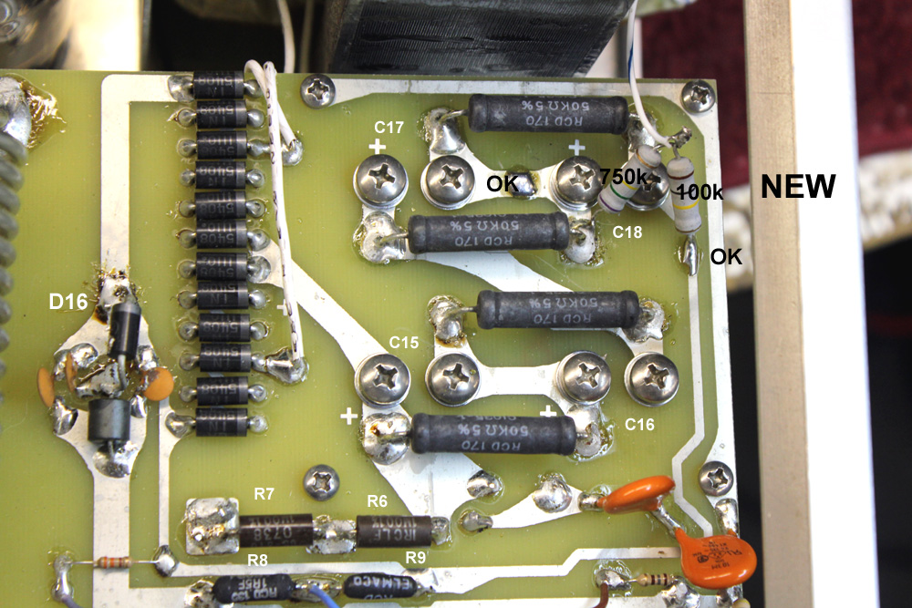
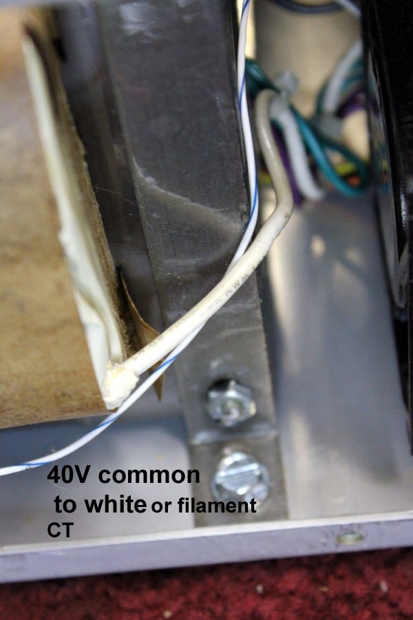
Center of 100k and 750k connect to white filament CT wire
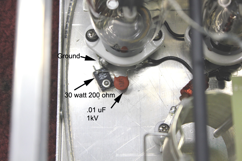
The acoustical noise comes from the ceramic disc capacitors normal piezoelectric effects. All of the .01 µF disc capacitors in the filament system, all four located on the rear panel circuit board, are involved. This is normal when a ceramic capacitor is subjected to very large voltage swings, and not an indication the capacitors are defective.
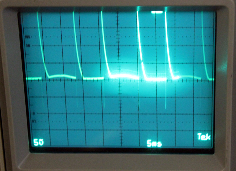
This scale is 50 volts per division. The sawtooth cathode voltage reaches 90 volts negative, and exceeds 200 volts positive, with the scope centered on zero volts.
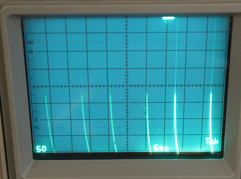
Peak positive voltages exceed 450 volts.
A 4.7K RF load resistor on the filament pin, R100 below, stabilized these tubes in the original AL811 circuit. Unfortunately, there is no assurance it will stabilize all tubes in all amplifiers. Because this is the only tube combination I have seen, I am basing this on a sample of only three tubes. Note that the FL2100 has stability issues with some tube types while on standby. These mods might help the FL2100, or they might not. This modification certainly will not hurt any 811 or 572B amplifier system.
I also disconnected the coaxial line from the tank to the rear panel circuit board, to be sure RF feedback was not occurring from output to input through the T/R relays. Disconnecting the coax made no difference. Loading the tank output with a low value resistance stabilized the amplifier, and eliminated the sawtooth.
Although 4.7K ohms stabilized this system, in my opinion it would be better to load the
cathodes as heavy as possible. The AL811 will eventually switch
to a pair
of 200 ohm resistors in parallel (~30 watts each). This should allow use of very sharp cutoff tubes
and increase the required drive level, but will also require tuned input circuit
changes.
It is better to add something, even if imperfect, to RF-load the RF path at the
filament in all 811 amps and 572B amps. This is because of production
inconsistencies
(variations) in 811A tubes. We can reasonably assume 572B tubes, since they use
the same grid assembly and filament, also have this problem.
Worse case peak RF cathode voltage is 100 volts. Typically, at full drive, average cathode RF voltage is around 75 volts. This is why I chose 150-volt breakdown gas tubes to protect the radio. If your amplifier has gas clamp tubes installed, and if they are firing, there is an abnormal reason they are firing. It is always better to find the reason for activation than to remove protection.
Using 100+ volts peak, or 75 volts RMS, as cathode drive voltage at the
cathodes, the safe resistor power should be
![]() where E is RMS voltage.
where E is RMS voltage.
| 2.7K | 2 watts |
| 1.0K | 6 watts |
| 470 | 12 watts |
| 200 | 28 watts |
The added resistor should be a low-inductance metal oxide type resistor. Any net resistance above 200 ohms will have minimal effect on input SWR, and not require more than a slight retouch of tuned input tuning slug position. The load resistor could be as many as thirteen 2.7K 2-watt metal oxide resistors in parallel. Do not use wire wound resistors, even non-inductive wire wound.
The popping occurs when a sharp cutoff tube has the input and output open circuited. New resistor R100 loads the cathode system of the amplifier, and prevents sharp cutoff tubes from oscillating.
Rsb is the typically seen, but generally unnecessary, self-bias resistor. I rarely use this resistor, installing it only in cases where it actually has a useful function. Adding this resistor makes the problem much worse, so much suggestion would be to never add this resistor, resistor Rsb, on a whim because you think it should have one.
The AL811, without any resistor at Rsb, floats to full plate current cutoff. This is almost always around 40 volts positive. The problem centers around tubes that only develop around 18-20 volts, or less, open circuit self-bias.
The following curves are from 811 tubes that behave normally, and tubes that oscillate with bursts of HF energy while on standby:
This is an unstable tube that breaks into oscillation. It self-biases into total cutoff at about 18 volts. In other words, if the filament center tap return is opened completely, the center tap only rises to about 18 volts positive. A normal tube, at least all the normal samples I have (about 50 tubes of various types), self bias to about 40 volts. This particular tube is unstable on higher HF bands even with a 47K filament CT leak resistance.
This is the plot of a stable 811A tube. It self-biases off, with a completely open cathode return, at about 40 volts. A totally open filament center tap floats up to +40 volts. This tube is stable at HF with any cathode leak resistance above 2.5 k ohms.
Blue curve is unstable HF tube on standby
Black curve is stable curve HF tube on standby
Note the curves converge and track at about 20 mA. All tubes I have tested have within a few percent same gain at normal drive power levels.