Heising Modulation
|
Heising Modulation |
|
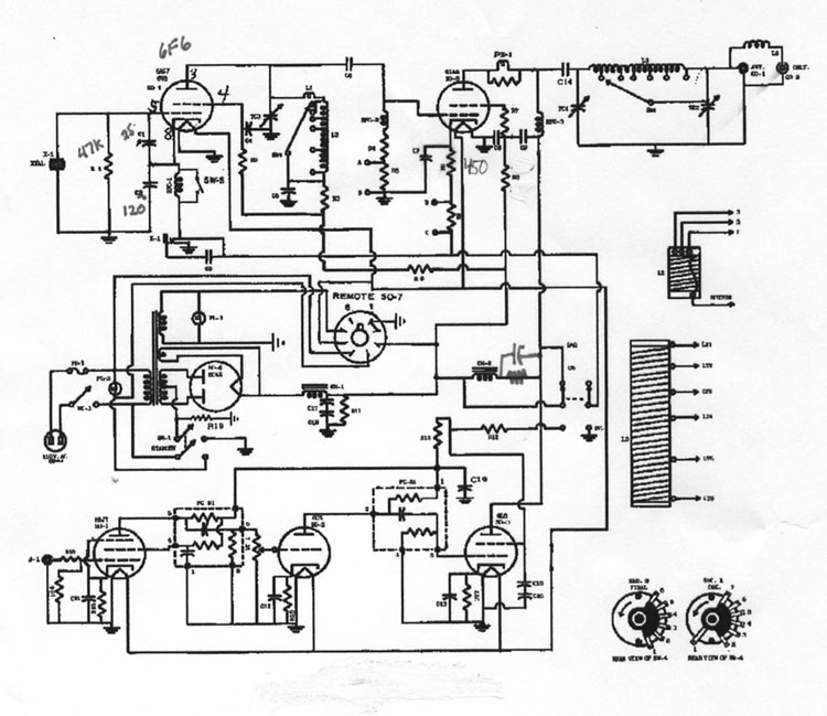
Also See: Viking Valiant Modulation modifications Heising modulation, also known as constant current modulation, was very popular in the early days of AM. It was largely replaced by conventional transformer-coupled modulation systems. The Globe Scout series was one of the very few transmitters still using Heising modulation in the twilight of amateur radio amplitude modulation dominance. By the mid-1970's, SSB was rapidly dominating HF voice operation. It is important to remember Heising modulation does NOT use a modulation transformer. Contrary to popular misuse on AM phone forums and on the air, a dc current bypass choke or modulation reactor used in conjunction with a transformer is NOT a Heising modulation system! The modulation choke or reactor in a transformer coupled systems prevents power amplifier steady-state current from flowing in the modulation transformer and biasing the modulation transformer core. While this is often called "Heising modulation" and the choke is sometimes referred to as a "Heising reactor", the use of "Heising" is incorrect. By definition Heising modulation has a 1:1 modulator impedance to PA impedance ratio. Heising modulation shares power supply current between a PA stage and a shunt modulator tube. When the modulator tube is biased "on", the modulator tube pulls current away from the PA stage. When the modulator tube is biased off, current is diverted to the PA stage. Power supply load current is nearly constant throughout the modulation cycle, hence the alternative name constant current modulation. Here is the Heising modulation circuit in my modified Globe Scout 65A.
How Heising Modulation Works Using the circuit to the left as an example, we can see why Heising modulation is simple, but limited in performance. Heising modulation operates in the following manner: The modulator tube (V1), like any conventional power amplifier tube, acts like a time-varying resistance. The anode-to-cathode resistance pulls the voltage at point A up and down at an audio rate. The large impedance or inductance of L1 allows the voltage at point A to move. L1, being a large reactance, stores considerable energy. During positive going modulator plate excursions (negative grid peaks) L1's collapsing magnetic field pushes voltage above B+ rail. L1 behaves like a flyback transformer. The collapsing field can never force the voltage up as cleanly or as far as a regular transformer-based push-pull modulator. This is because of flux leakage and losses in the Heising modulation choke. The best type of choke would be one with the lowest flux leakage. This is not the type we normally find or want in power supply filtering. Power supply filter chokes normally have an air gap in the laminations. This gap is created by stacking the laminations all E with E and all I with I. The more desirable stack in a modulation choke would be an alternated E and I position. This minimizes air gaps and significantly reduces flux leakage. If you look carefully at power transformers you will see they use alternating stack positions between the E's and I's. Filter chokes, for the most part, run all I's at one end of the lamination stack and all E's at the other end of the core stack. Another way to view operation is the modulator tube (V1) and PA tube (V2) share current through L1. A basic inductor property is the inductor tries to readjust voltage to maintain constant current flow. While capacitors try to maintain constant voltage across capacitor terminals with varying current, opposite behaving inductors try to maintain constant current through terminals while allowing voltage to vary across terminals! When modulator tube current decreases, the collapsing field in L1 causes an increase in voltage at point "A". The PA tube has higher operating anode and screen voltages. Current that formerly went through the modulator tube now goes through the PA tube, along with the higher voltage. When the modulator tube draws increased current, the choke tries to oppose the current change. Because of increasing current, the choke generates a counter electromotive force. This voltage opposes modulator and final amplifier supply voltage. In this case PA and modulator tube voltage is reduced. Current that was flowing through the PA tube is now diverted to the modulator tube. This is why Heising modulation is called constant current modulation. Current from the supply is constant. The supply current simply shifts back and forth between the modulator tube and the PA tube. There is one more important consideration and an interesting exception to rules, the modulator tube. Current into the PA/modulator section in a plate modulated Heising has to be constant. This means the modulator tube has to be class A, and biased to idle near or even above the plate current into the PA section. The modulator tube has to draw at least as much current as the PA section to provide linear modulation. There exception to this is with a tetrode tube. Because the tetrode is combination screen and anode modulated, we do not need to double anode voltage for 100% positive peaks. We also do not need to take the anode to zero volts for 100% negative peaks. In the Globe Scout, zero envelope is reached with 30-35 volts on the 6146 anode. 100% positive envelope peaks are reached at about 185% of resting anode voltage. The 6L6 can be biased to about 70% of the 6146 current with minimal distortion, because both the 6146 anode and screen are modulated. Linearity and DistortionThe modulator tube and modulation choke must never be allowed to go into non-linear regions. The resulting harmonic and intermodulation distortion will appear (unfiltered) as modulating voltage and cause splatter. This is true even if the percentage of modulation is well below 100%. One test of proper linearity is to measure current from the supply through the modulation choke, L1. If power supply current flowing through L1 changes at an audio rate, the modulation cannot be linear. This is the basis of constant current modulation. Of course we can and we should use conventional distortion measurement techniques to measure distortion, but constant current is a novel characteristic of perfect Heising modulation. There are also limits in anode voltage swing on the RF power amplifier tube. Even with with positive grid voltage causing a fully saturated modulator tube, the modulator can never pull voltage to zero. Voltage at point A can never lower than positive voltage at point C. As a matter of fact, the lower voltage limit at point A on negative cycles is always greater than the positive voltage available at point C. This limits modulation to less than 100%, unless a dropping resistor is included somewhere between the modulator anode and the PA voltage feed. The resistor can be at any point that limits anode to cathode voltage in the modulator to a value significantly less than the lowest voltage obtainable at the choke and modulator anode connection junction with full linear positive-going modulator grid voltage.
Modulator current flows through 390 ohm cathode bias resistor R101. Any voltage on the cathode, even steady bias voltage, reduces negative modulation peaks. It is imperative to bypass the cathode bias resistor R101 with large value bypass capacitor C202. C202's reactance must be low compared to R101's resistance. Without C202 across R101, the cathode will lift on negative modulation peaks (when the grid of the 6L6 goes positive). This is a downfall of the original Globe system. Grid bias of the modulator tube would have been best. Lacking that, they also never included a low-reactance cathode bypass capacitor. Omitting C202 only made an undesirable situation much worse. Since modulator and PA anodes are in parallel for audio signals, the anode voltage swing in the modulator and PA track each other. This means the 6146 PA has voltage swing limitations similar to the modulator tube. Because of the lower voltage limit established at point C and point A during positive grid voltage swings, the 6146 anode can't possibly reach zero voltage on negative modulation envelope peaks. The solution is the addition of R106 and C110. Resistor R101 causes the anode of the 6146 to operate at reduced voltage. C110 provides a low-impedance path for audio variations. Both are necessary to achieve 100% negative modulation peaks. Modulation Problems with Tetrode Power Amplifier StagesTo 100% plate modulate any power amplifier RF output must follow the square of the anode voltage. If the resting anode voltage is 1000 volts and the carrier power is 100 watts, the net RF output power must reach 400 watts when the anode is at 2000 volts. Output must reach zero watts when the anode reaches the full negative peak. This only occurs when the plate current tracks the plate voltage change. Doubling the voltage doubles the current, and this quadruples the RF output power. The RF load impedance also stays uniform; voltage and current are changing in the same proportion. This condition of perfect AM, with only plate modulation, can only occur in deep class C low-mu triodes or FET's that are neutralized or that have insignificant driver feedthrough power. Such devices will have square law power output as supply voltage is modulated. Anode current in tetrodes is largely controlled by the screen voltage. While anode voltage can be run up and down, anode current will not proportionally track the changes in anode voltage. A tetrode will not have linear, low distortion modulation unless we also properly modulate one or more of the grids. In other words we must use a combination of grid and plate modulation. (We could also correct the problem by modulating the driver stage along with the PA anode.) For 100% linear modulation in a tetrode stage, the screen must follow anode modulation in the correct proportion. This can be accomplished by operating the screen from the same modulated source feeding the anode. Correcting Screen Swing in the Globe ScoutOnce again we can look at my Globe Scout schematic.
C113 increases audio voltage applied to the screen. In some radios it might be necessary to add a series resistance with C113, but best modulation linearity and lowest distortion occurred in my Scout without a resistor in series with C113. This system worked best with full modulation swing on the 6146 screen. In other cases screen resistor R107 may or may not require shunt capacitor C113. If C113 is required to achieve 100% linear modulation, the screen's audio voltage can be limited with an additional resistance (not shown) in series with C113. (Rather than adding a resistance in series with C113, the resistance of R107 could be split between two series resistors. C113 could then only bypass one resistor. R107 could be a tapped adjustable resistor of the proper value to establish proper screen voltage, with C113 between the slider and the end.) Any resistor in series with C113 should be selected for best modulation linearity.
My Globe ScoutThe circuit above is the actual circuit used in my modified Globe Scout 65A. C113 required a large series resistance in my Scout, about 22K ohms. This resistor is NOT shown on the schematics above. The resistor value was determined by watching modulation linearity. I use a sine-wave audio generator, comparing the diode-detected audio of the RF output to the generator audio output. A standard trapezoidal pattern would work also. Remember, the resistance in other systems might be different. R101 sets the quiescent current of the 6L6 at the maximum allowable dissipation of the tube. I used a 6L6GC, which has higher dissipation than a regular 6L6. I adjust R105 to set the 6L6 at the maximum dissipation limit. I generally operate the 6146 PA at the same current as the 6L6 while operating AM. This modified system allows 100% negative peaks and nearly 100% positive peaks with voice. PA current is about 55-65 mA, or 30 watts. In class C operation, my Globe Scout runs about 18-20 watts carrier output. Notice R109. This resistor is a 2 watt high voltage type resistor that connects to the cathode of the 6J5 triode in the audio amplifier. The bypass capacitor is removed by snipping the white wire at the cathode pin. The 6J5 is a weak link in the Globe audio system. Bias is too low. On positive peaks, the 6J5 grid actually goes into conduction. This clips the signal from the gain control, and limits positive peaks. R109 does two things. It biases the 6J5 closer to cutoff, allowing the grid to swing more positive before drawing current and limiting. It also adds negative feedback, reducing non-linearity in the 6L6 modulator tube. I tried removing R101 and using grid bias to reduce the lower-voltage limit (because point C could be chassis ground), but the actual gain in negative peak linearity was too small to make the mod worthwhile. I also added a grid leak resistor, a screen clamp set at 225 volts, and a fixed grid bias source. The fixed bias is set so the Globe draws about 40mA with HV and no excitation. It is important you do this, because the original 6146 cathode resistor of 450-ohms adds negative bias that decreases modulation level and linearity. If you want to leave the 450-ohm resistor in, I suggest adding an electrolytic capacitor for audio frequency bypass. In that case it would not be harmful, and you could omit C110 and R106. I have not tried this because I converted my Globe to grid block keying and eliminated the 450 ohm resistor long before starting audio modification. With no other mods the Globe Scout is flat from 200Hz up to about 3500Hz, where it starts to roll off. By 6000 Hz audio is 6dB down. The Globe Scout audio is comparable to any other good radio (Ranger, etc.) on AM. This is the original Globe Circuit. (The penciled-in components were from a mod I made in 1963) :
|