Viking and Ranger Valiant Modulation modifications
About Power
One of the first things we must understand before discussing characteristics of AM is power measurement. First, there is no such thing as "RMS Power". We find power by multiplying RMS voltage times RMS current, but there is really no such thing as "RMS power".
What does exist is equivalent or heating power. This is useful power over a defined period of time, even a very short time. It is power that does, or can do, some amount of actual work. Both PEP and average power are based on the heating or work power, even if that heating or work power is taken over a single RF cycle.
The old common method of quantifying RF power was average power. Average power is same as equivalent work power or heating power of each cycle averaged over a significant time compared to the time when power level changes. With an unchanging (during the measurement period) power level, such as a steady unmodulated carrier applied to a constant resistance load, average power and peak envelope power are the same. If we close and hold-closed a manual telegraph key on a good stable CW transmitter, we will see the average power displayed on a power meter. It will not be the "RMS power". It is also the peak envelope power, because it is the maximum stable heating power level over some period of time that we hold the key.
As for peak envelope power, peak envelope power is the very maximum short term peak reached of either steady or varying heating power levels!
Consider a sine wave with a peak voltage of 100 volts. The RMS voltage is 70.7107 volts, or 100 peak volts. If we placed that voltage across a 50 ohm resistance we would have 70.7107 / 50 = 1.414214 amperes. That would also be 100 watts average power in one complete cycle or any number of equal amplitude cycles that follow. The peak envelope power is also 100 watts because the peaks are the same cycle after cycle.
If we pulsed that power off and on rapidly with a 50% duty cycle the average power would be 50 watts. Half the time it would be 100 watts, and half the time zero watts. The peak envelope power would be 100 watts, because that would be the power at the crest of the envelope! The envelope can be as short as one cycle, although no meters ever respond to that.
Power cannot be RMS power. RMS is calculated by squaring the function's value, taking the average (mean value) of the squared function, and finally converting that mean value back by finding the square root of that mean. If we had a peak power of 100 watts with a 50% duty cycle the RMS power, if there was such a thing, would be SQRT( (100^2 + 0)/2) = 70.71 watts. We see that 70.71 watts is not the average power, is not the heating or "work" power, and is not the peak power. It isn't anything at all useful! We can have meters that read RMS voltage, and we can also have RMS current, but we don't read "RMS power" with any of our power measuring instruments. We can't even calculate RMS power to be anything useful or sensible at all.
Let's consider the case of perfect undistorted sine wave modulation of an amplifier stage. The carrier, sidebands, and power levels of the various spectral components making up the signal have a certain ideal relationship. Consider the case below with symmetrical sine wave modulation.
Unmodulated carrier = 100 watts (PEP or) average carrier power.
Average is the same as PEP because, absent amplitude modulation, the carrier level is unchanging over time.
100% steady modulated 100 w carrier = 400 watts PEP or 150 watts average or "heating" power. Of this 150 watts average or "heating" power, 100 watts is in the carrier, and 25 watts average power is in each of the two AM signal's sidebands.
Carrier average power = 2/3 of the total 100% modulated average power
Total of both sidebands, average power = 1/3 of total average power under 100% modulation
Average power one sideband = 1/6th average power with 100% modulation
Peak Envelope Power 100% symmetrical modulation = Four times carrier power
Plate Modulator Requirements
100% sine wave modulation of a 100-watt carrier requires a modulator sine wave power of 50 watts. This audio power directly adds to the PA's RF power, making the total heating (or average) power 100+50 = 150 watts.
On 100% positive audio peaks waveform, as seen on an oscilloscope, doubles in voltage. Doubling load voltage on audio peaks also doubles load current on audio peaks. This means any AM signal with symmetrical 100% modulation, when measured using true PEP meters, has four times carrier power.
If we monitor transmitter output current on a typical slow-response RMS current meter, like a typical thermal RF ammeter, we should observe current rising to 1.22475 times steady state current with steady 100% modulation. We should also observe an average RF voltage of 1.22475 times the unmodulated carrier voltage, when steady sine wave modulation of 100% is applied. This is 1.5 times the unmodulated carrier average power, and fully accounts for the carrier power plus the 50% audio power required to modulate that carrier at 100% modulation.
One word of caution, measured values are affected by the type of meter we use, and the modulating waveform! Some metering schemes don't fully respond to peaks, and some don't fully read the average either. This is a metering problem.
We will not see the 100% sine wave modulated average power levels with perfect 100% modulated speech, although PEP will indeed reach four times the carrier on a good sample and hold meter. This is because speech has a larger peak power to average power ratio, when compared to peak-to-average power ratio of steady sinewave modulation. A true peak reading meter with adequate peak-hold time is, by far, the most reliable way to measure positive modulation peaks. A true peak-reading RF power meter, with adequate hold time, is actually a much more accurate indicator of 100% positive peaks than a conventional oscilloscope.
The best overall modulation percentage indicator would be a specialized device that sampled and held negative peaks, and also sampled and held positive peaks. This would not indicate bandwidth of course, only percentage of modulation! Actual bandwidth would only be indicated by using a peak holding spectrum analyzer or, in a pinch, a very narrow bandwidth tunable receiver with a peak responding and slow decay calibrated signal level meter.
Plate modulation might well be the most common method of obtaining amplitude modulation. Most amateurs consider plate modulation in a very favorable manner, and many of us are capable of building a simple rig we call "plate modulated". Most older tube gear uses a system called "plate modulation". What isn't often understood is the system often called plate modulation is often not true plate modulation, but rather a combination of plate and screen modulation!
In order to be purely plate modulated without distortion, a plate modulated RF power amplifier stage must maintain a square law power output function with varying plate or anode voltage. As a matter of fact this can actually be called parabolic, or square law, modulation. If peak PA anode voltage increases 50% from modulator power (50% modulation), peak envelope RF output power should increase 225% over the carrier value. If the modulator doubles plate voltage (100% modulation), positive peaks of envelope power output should quadruple (400%) from carrier values.
The reason for this squaring of power is logical and easily understood. With 100% symmetrical modulation, the plate modulator system doubles anode voltage on positive peaks. When tube anode voltage doubles, assuming the tube behaves like a constant average resistance, this also doubles anode current. Doubling current and voltage at the same time obviously means plate input power is four-times initial resting power. Efficiency remains constant at a pretty high value in a class C stage, causing peak RF output power to ideally be four-times the unmodulated carrier value with a 100% modulation and symmetrical modulating waveform signal!
The above assumes real 100% plate modulation. Most amateur
rigs and not pure plate modulation, but are a combination of screen and plate
modulation. We just call them "plate modulated" rigs.
True
plate modulation has the same PA load, or PA operating impedance, all
through the modulation cycle. This occurs because any change in anode voltage
results in a proportional change in anode current. The product of anode supply
E/I is constant across all voltage swings. Doubling anode voltage proportionally
doubles anode current.
Methods of "Plate" Modulation
There are several methods of obtaining "plate" modulation. The two most common in amateur use are Heising modulation and standard plate modulation. Heising modulation is also called constant current modulation. There are details of Heising modulation on my Heising Modulation page.
It is very popular among amateurs to call the modulation reactor a Heising choke, and to call a conventional transformer coupled modulator Heising modulation when it has a modulation reactor, but it is NOT Heising modulation. Contrary to what amateurs popularly claim, plate modulation with a transformer and modulation reactor is not Heising modulation and the modulation reactor is not a "Heising choke". The reactor serves only to keep steady-state PA current out of the modulation transformer, giving the transformer more headroom before magnetic saturation is reached.
Heising modulation is constant current modulation, in that the modulator tube and PA tube share the same reasonably-constant power supply current level. The power supply current shifts back and forth between the PA tube and the modulator tube, but the supply load is for all practical purposes constant. Heising modulation never uses a transformer, but rather parallels the PA stage and a modulation with both being fed through a modulation reactor or choke. One of the few rigs to employ Heising Modulation is the Globe Scout.
The modulation choke, when used with transformer coupling from the modulator system, simply serves to keep dc plate current out of the modulation transformer and keep flux levels low in the modulation transformer. The modulation reactor improves performance of the modulation transformer by lowering flux levels cause by dc current flowing through the secondary winding. It serves no Heising function at all.
Plate Modulated Triodes
As a general rule only plate modulated low-mu or medium-mu triodes provide needed square-law power response with modulated anode voltage variation. The ideal response generally occurs only when a triode is operated well into class C with short conduction angles. A triode operating in this manner behaves like a rapidly off-and-on switched resistance (switched at the RF excitation rate). This means the triode presents a nearly constant load resistance to the much lower frequency plate modulator system. Some of the cleanest, least critical to tune, high-level modulated AM transmitters use low-mu triodes.
| A | B | C | |
| 1 | .4 | .05 | 0 |
| 2 | .6 | .1 | 0 |
| 3 | .7 | .2 | 0 |
| 4 | .83 | .3 | .05 |
| 5 | 1.0 | .42 | .1 |
| 6 | 1.2 | .58 | .2 |
| 7 | 1.4 | .7 | .3 |
| 8 | 1.5 | .8 | .4 |
| 9 | 1.7 | 1.0 | .55 |
| 10 | 1.9 | 1.2 | .67 |
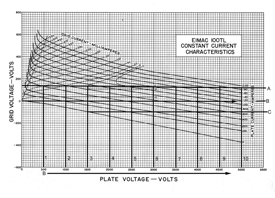
We can see a low-mu triode, as plate voltage increases, has a substantial increase in plate current. If we pick the correct loadline, the input power will approximately quadruple for every doubling of anode voltage.
For example at A5 we have 1 amperes at 2500 volts, or 2500 watts input power. At A10 we have 1.9 amperes at 5000 volts, or just under 10,000 watts instantaneous plate power.
Remember this is instantaneous power, since the anode current is in very short pulses in class C. The average power is MUCH less. Tube anode heat is an integration of these short pulses of very high dissipation. The thermal mass of the anode averages the heat.
Linearity is not perfect with the 100TL, but if we pick the correct operating loadline, the tube provides very close to square-law response. If the modulator doubles anode voltage, peak power would nearly quadruple.
Let's look at a tetrode.
Plate Modulated Tetrodes (and pentodes)
An ideal tetrode or pentode tube with fixed grid voltages has
constant current characteristics. The anode current does not track with anode
voltage. A "plate
modulated" tetrode or pentode,
without the aid of
supplemental grid modulation,
will not follow desirable square-law
power performance. This is
because screen
grid voltage dominates
cathode-to-anode current in a
tetrode (or pentode).
The tube does not operate at a constant, stable, E/I ratio (impedance) over the modulation cycle.
Production of linear undistorted modulation requires a combination of grid and anode modulation.
The tank circuit tuning is also critical, since the tube functions partly as as
a grid modulated stage.
Deriving screen voltage through a high
resistance, so the screen has a high audio frequency impedance to ground, is
common method of adding grid modulation to a "plate modulated" tetrode or
pentode. A better way is to add an intentional amount of audio to the screen.
Whatever method is used to get around the constant current effects in the
tube the stage also becomes sensitive to tank loading. Unlike with a low mu
class C triode, tetrode and pentode operating impedance varies with supply
voltage. The tank has to be "tuned" (as does a linear) for the lowest impedance
(highest peak power).
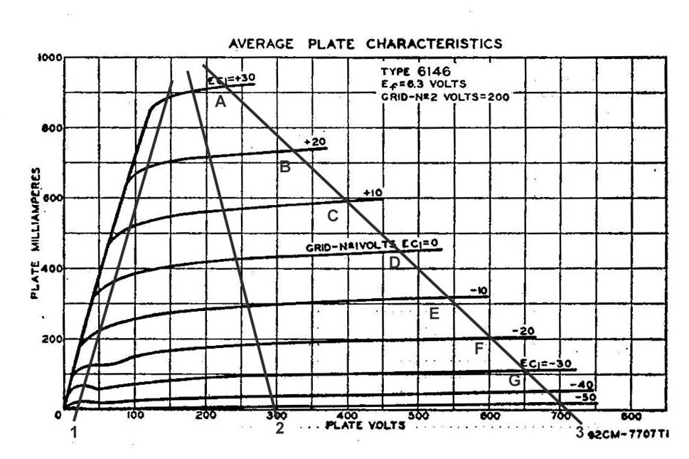
Let's look at a commonly used amateur beam power tube, the 6146.
Curves A through G represent anode current as anode voltage is varied with constant bias and screen voltage applied. Notice how flat the plate current curves are as anode voltage is varied.
If the modulator doubles anode voltage in an ideal tetrode or pentode amplifier, plate current would not change at all! Most tetrodes are not perfect and will do a little better than this, but still have considerable distortion when exclusively plate modulated.
If we plate modulated a typical pentode or tetrode like the 6146, the system will only achieve 50-60% positive peaks (200 watts PEP for a 100 W carrier) by the time negative peaks reach 100%. For example at -30 volts bias with 200 volts on the screen (curve G), anode current is about 100 mA whether anode voltage 200 volts or 700 volts. If only the anode was modulated, audio would be highly distorted. With true plate modulation of a tetrode, it impossible to obtain 100% positive peaks. Even negative peaks would be grossly distorted.
The easiest way to properly plate modulate a tetrode is to screen modulate at the same time the PA stage is anode modulated. By applying the correct proportion of modulating voltages to the screen grid and anode, with neither element actually modulating 100%, the system can come very close to producing the desired square law power response. The exact ratio of modulation applied to the screen and anode varies with tuning, loading, grid drive, tube type, and operating voltages. A properly designed plate modulated tetrode is actually not plate modulated, but rather is partially plate and partially screen modulated. We could also modulate the control grid along with the anode, leaving the screen fixed in voltage. We could modulate an earlier exciter stage in combination with the plate of the final amplifier. Still, the most common plate modulation method of tetrodes, and the method that seems to work adequately, is a combination of screen grid and anode modulation.
There are two ways to combine screen and anode modulation. One method "forces" the screen to follow modulated anode voltage by supplying the screen from voltage taken on the power amplifier side of the modulation transformer. This method is shown below:
C4 (screen bypass) must have high reactance at the highest audio frequency when compared to the parallel combination of R1 and R2.
C6 (screen supply blocking capacitor) must have low reactance at the lowest audio frequency when compared to R2.
R1 determines screen operating current and voltage.
R2 is adjusted in value to provide the best audio linearity at the design value of plate and grid operating currents and voltages. This resistor determines the amount of audio supplied to the screen grid.
A second method is to let the screen self-modulate:
C4 (screen bypass) must have high reactance at the highest audio frequency when compared to R1.
C6 (screen supply blocking capacitor) must have low reactance at the lowest audio frequency when compared to R1.
R1 determines screen operating current and voltage. This resistor must be very high in value, probably over 5,000 ohms in most cases. If the resistor cannot be made high in value, a series choke that has very high reactance across the audio spectrum must be added in series with R1. R1 is often compromised in value to provide the best audio linearity at the design value of plate and grid operating currents and voltages. This resistor determines the amount of audio supplied to the screen grid.
Self-modulation of the screen works because screen current varies with anode voltage. The screen system, in effect, becomes a constant current supply for the screen grid. As the plate modulator pushes anode voltage higher, screen current decreases. Decreased screen current causes screen voltage to increase. This system, when a series resistor is used, normally requires the screen supply voltage to be at least 50% higher than required. With a screen choke, the screen supply voltage can be equal to the desired screen operating voltage. For a 6146 with the resistor method of supplying constant current, the screen source voltage should be at least 300 volts. Screen voltage is often sourced from the anode supply line.
Since the tetrode (or pentode) stage is both screen and anode modulated, high voltage supplied to the anode system does not reach double carrier voltage on 100% positive peaks. More important, and a point many people seem to miss, is the modulated anode source voltage does not reach zero for 100% negative peaks! If a negative peak limiting circuit is installed in the modulator system of a "plate modulated" tetrode (or pentode), the stage will normally go well beyond 100% negative peaks without crossing over to negative voltage. The scope display below is a good typical representation of modulator voltage supplied to the 6146 power amplifier in a Johnson Ranger II.
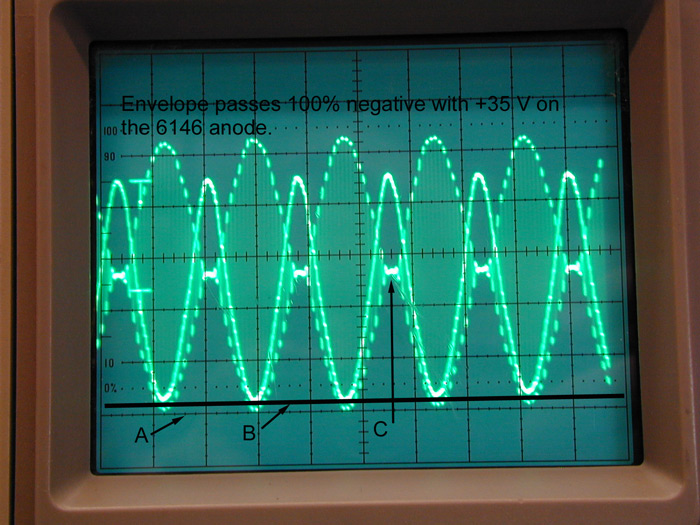
For more details see Johnson Ranger and Valiant Audio mods.
There is an important lesson to be learned from this. Some articles claim a negative peak limiter, or blocking diode, can be used to prevent over-modulation on negative peaks. That claim is clearly false because a properly configured 6146 (or any other tetrode) reaches 100% negative peaks while the anode is still significantly positive. In the case of the Johnson Viking Ranger a properly designed negative peak limiter would hold the anode at least at 40 volts positive, and have filtering to round the transition off and not create sharp waveform edges near the negative limits. This is almost impossible to do at high levels. It would be much better accomplished in low level stages.
There are two basic systems that use efficiency modulation, grid modulation and linear amplifiers. A linear amplifier or grid modulated stage has constant anode voltage. Just as changes in anode voltage from modulation do not change current linearly, changes in drive level can only change anode current. When we vary current in a device without a corresponding change in voltage, we normally do not have a square law power response. With fixed coupling to the load, if we match at full peak power, lower drive levels cause a reduction in efficiency. This is because, unlike with plate modulation, anode supply voltage does not vary. With a conventional deep class-C triode with plate modulation, the output device acts presents a constant time-averaged resistance to the modulator. If the modulator doubles anode voltage, anode current also doubles. Since anode voltage and anode current changes in the same proportion, they maintain the same ratio. Anode impedance is E/I, and if the ratio remain constant the anode RF impedance also remains constant. The output device sees the same match (or mismatch) at zero modulation as the output device sees at modulation positive peaks or modulation negative peaks, and with the same conduction angle efficiency remains the same.
Screen modulation, control grid modulation, or linear amplifiers all have a constant anode or collector voltage. This means output device impedance, or E/I of the output device, varies over the audio cycle. The device has highest current on modulation positive peaks, and lowest current on modulation negative peaks. This means the mismatch between the output device and the load varies over the modulation cycle. The normal tuning procedure is to match the output device at maximum positive modulation peak. As the modulation positive peak is reduced the output device has a higher impedance, and this mismatches the device to the tank. The result is a reduction in efficiency as the system moves below the peak positive modulation level, reaching minimum efficiency at maximum negative peak.
The approximate rule with 100% modulation is device carrier efficiency is half of the device positive peak efficiency. Let's say we have about 70% efficiency at the anode of a tube with 4% tank and other losses for 66% total efficiency. At carrier, plate efficiency will be about 35%. With tank losses of 4% we have an overall efficiency of 31%. This means on carrier 2/3 of the plate input power will be heat, or twice as much heat as carrier power into the tank. With 500 watts PEP output on modulation peaks, the tube anode dissipates about 375 watts of heat.
This is true for screen modulation or linear amplifiers!
Many linear amplifiers with high conduction angles only have about 50% efficiency on peaks, plus the normal procedure is to slightly over-couple to ensure linearity on occasional exceptionally high peaks. This means with an unmodulated carrier, that same amplifier might be down around 25% plate efficiency. A safe general rule for linear amplifiers is output device power dissipation is three times the carrier power when amplifying the unmodulated carrier.
This means a legal-limit AM linear could have about 1125 watts dissipation during carrier conditions of 375 watts, and on positive modulation peaks output power will be about 1500 watts with 1500 watts of short-term dissipation. This is a reasonable safe estimate.
If a conventional AM linear or screen modulated stage is making more than half the peak efficiency on carrier, odds are very good it has excessive distortion and splatter.
It may not seem like it at first glance, but grid modulation and linear amplifiers use similar principles. As such, they can be discussed together.
Low level modulation
often has much less
distortion and more
fidelity than high
level modulation of
tetrodes, and more
faithfully
reproduces the audio
input. It is much
easier to have low-distortion high-fidelity audio using
low-level
modulation. To be
sure, some of the
cleanest AM BC
transmitters ever
built were low level
modulated systems.
Unfortunately the
low efficiency
resulted in high
energy consumption,
causing most
stations to use more
energy efficient
high level
modulation.
The sole shortfall
with linear amplifier or
grid modulation schemes is
efficiency. In order
to reproduce the
input faithfully,
the amplifier has to
be loaded to handle
the PEAK power. This
is normally four
times the carrier
power (or more in
some cases). This is
because the linear
has to be
"efficiency
modulated".
A safe estimate is
25% carrier
efficiency. This
means your amp would
be making three
times the heat as
carrier power. An
SB220 can safely
handle about 500
watts of steady
dissipation
(inadequate airflow
to fully use the
tubes) so it is safe
at 125 watts carrier
when properly tuned.
Very few amplifiers
can safely
handle legal limit
AM. Legal limit AM
requires
375 watts of carrier
power,
and three times
carrier power would
be a safe power
amplifier
dissipation estimate
for
carrier-level heat dissipation.
Typically, with a
375-watt carrier,
over 1100 watts
of heat is produced.
This
takes a lot of air
and a 1200-watt or
higher plate
dissipation tube. An
8877 at full rated
airflow, or a
3CX1200 series tube, would work.
A rig certainly does
NOT need to be plate
modulated to sound
perfect, and as a
matter of fact most
amateur plate
modulated
transmitters have
terrible distortion
as a percentage of
modulation. It's
just that most
people can't
actually hear the
distortion, they
listen to and enjoy
the frequency
response and might
actually "like" a
little distortion,
and they confuse
distortion with good
sound.
Contrary to popular myth,
there is no
difference in the
sound of any AM
transmitter when
amplified in a
properly tuned and
operated linear
amplifier. This is
because a properly
tuned and operated
linear, be it a
Heath SB220 or
anything else, has
much less modulation distortion
than the typical
boatanchor rig. The
real problem with a
linear is NOT the
sound. The
real problem is
heat
caused by poor
carrier efficiency.
It's certainly
possible to have bad
low level
modulation, but
plate modulating a
tetrode also guarantees
we have to do
special tuning and
add "circuit tricks"
to avoid significant
distortion. While
the plate modulated
tetrode system
reduces problems
with loading, drive
power, and heat, it
does not eliminate
these problems.
Additionally,
high-level
modulation requires
a high power
modulation source
with low distortion
and adequate
fidelity.
To be linear all stages must be tuned or loaded at full peak envelope power, plus a little safety factor. In other words if we are going to 1500 watts PEP output, we must load the amplifier stages to 1500 watts carrier or more! After loading at full peak power, carrier is set at less than 25% of the peak power. Failure to do this will result in modulation distortion called "flat-topping". The result will be very wide bandwidth splatter and "downward modulation".
If we are going to run 100 watts AM carrier, all stages must be tuned for at least 400 watts of peak power.
Some newer HF transceivers are excellent on AM, with much less distortion and better fidelity than most older amateur AM rigs. The Ten-Tec Orion and the Yaesu FT-1000D are two examples of very good AM transceivers.
Peak envelope power,
with 100%
modulation, is four
times carrier power.
For 100% modulation
in a 100-watt radio,
a 100W PEP radio
must run 25 watts or
less carrier. With a
100-watt radio, peak
power on voice peaks
should be held to
100 watts or less.
I used an
IC-751A or IC-706
ICOM on AM. The
problem with that
ICOM, like with many
HF SSB radios, is it
uses ALC to
limit output power. Turning
the output power
down or mic control
up will not increase
the percentage of
positive peaks. This
is because the
ALC system in most
SSB rigs almost
always detects
peak power. If we
adjust carrier power to 25
watts and try to
modulate 100% (100
watts), the peaks
cause the radio to
reduce gain until
peaks are back at
the 25 watt carrier power
level. The positive
peaks stay at 25
watts or so...and
the carrier drops to
7.5 watts when
modulated!
The cure is to run
the power level all
the way wide open
and apply an
external stable
negative voltage to
the external ALC
input. Adjust the
external negative
ALC until the
carrier is 20-25
watts, and then the
mic control until
we have 100 watts
on peaks using a
good peak reading
meter.
An external ALC
carrier control can
be a 9V battery
across a 500k pot in
a voltage divider.
The positive battery
lead goes to ground,
and the ALC output
comes from the pot
wiper. P1 goes to
the EXT ALC jack on
the radio.
Remember to disconnect the battery when using other modes or when not using the radio!
To use this circuit, run the radio's normal power control wide open. Adjust the pot for 20-25 watts carrier. Adjust the mic control for 100% modulation, or 100 watts PEP (on a 100W radio).
as of 2/7/2010