Also see:
45G tower page
Rotating Tower page
Antenna System and my house station
A ground will not....
My grounding.....
|
My station is located in middle-Georgia, just off I-75, in grid EM73XB and Lamar County.
It is a rural agricultural location with few local power lines, the nearest high tension lines are miles away.
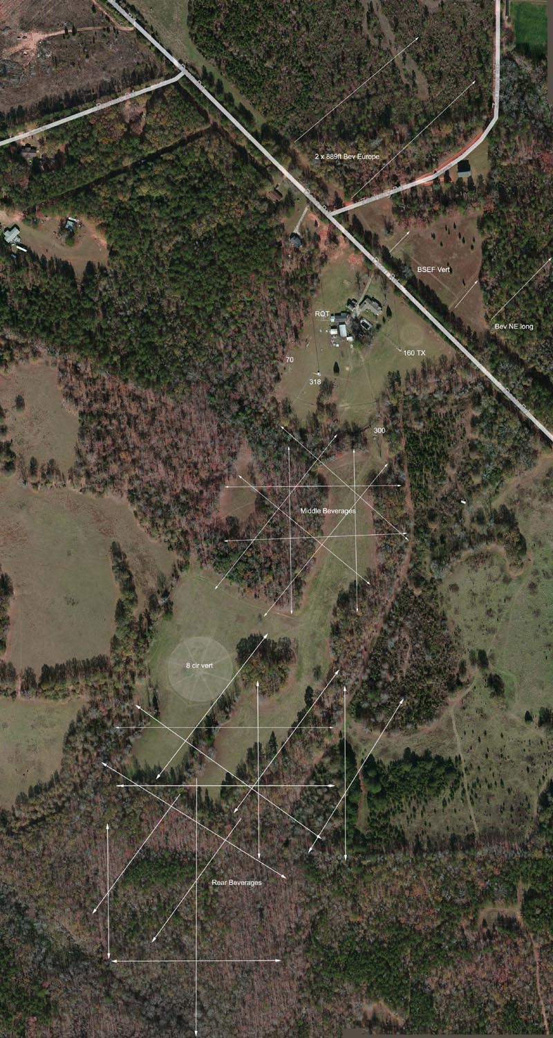
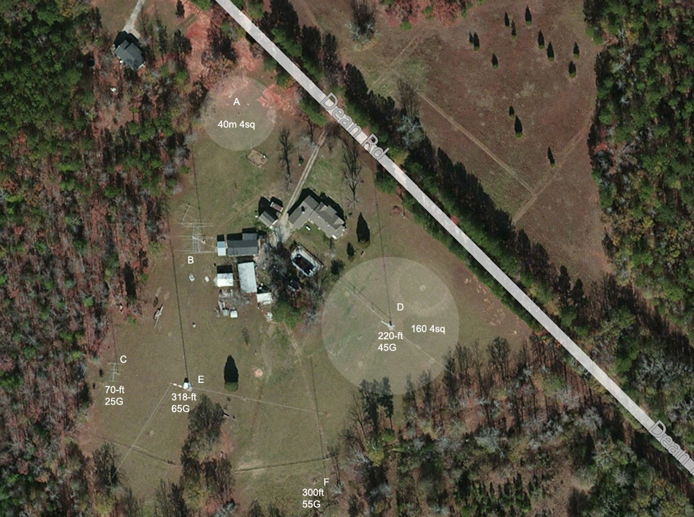
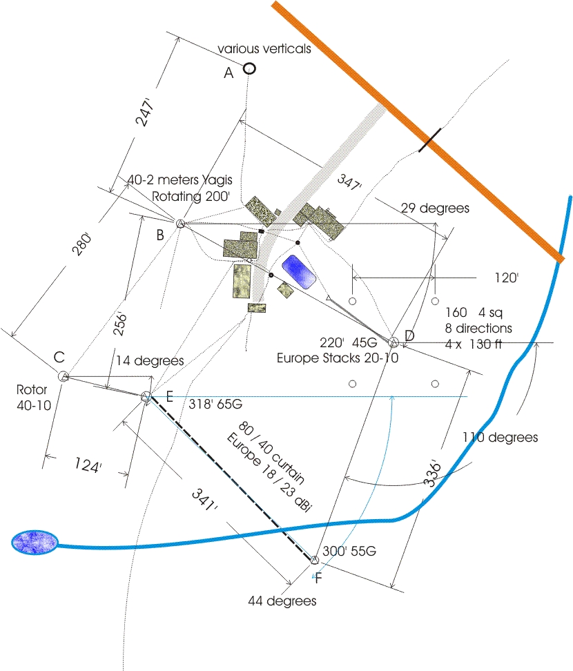
Basic overall property showing antenna layout:
Underground control wire and feed line routing.
Tower position and spacing.
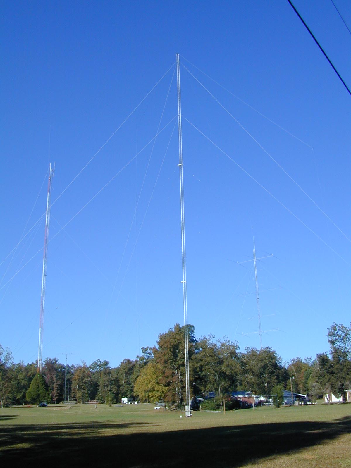
Left-to-right 318ft 65G, 70-ft 25G background, 200-ft 45G foreground, 200-ft rotating background
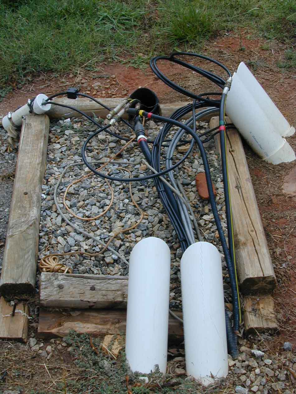
Cables and conduits arrive from different directions at connection islands.
New cables are easily installed through 4-inch diameter pipes, either flexible black drain pipe or PVC. All pipes have drain holes and gravel at low spots for drainage.
I try to keep receiving and control cables in one pipe and transmitting cables in the other pipe, mostly to make wiring easier to follow. I find very little electrical advantage.
I use tape "color codes" to keep track of cables.
Some cables are directly buried under the pipes.
All transmitting cables are 50-ohm, all receiving cables 75-ohm. The large hardline and heliax cables in this photo are all 50-ohm.
The red/green taped cable with the yellow stripe is a flooded aluminum jacket CommScope "50-ohm power cable". In the event the jacket is cut, flooding compound between the jacket and shield re-seals the cable. This cable has a very large solid-copper center, and the shield is .625 inches OD. It is very tough cable, suitable for direct burial. I have about 1,500 feet of it in my transmitting system.
Other cables, like the red/white and red/yellow marked cables, are traditional heliax. Solid copper jacket heliax can be directly buried. Most of this cable has been pulled from Cell and Two-way towers. The average price for good used heliax cable is about 75-cents per foot.
The silver cables are control cables. Each control cable has 44 shielded conductors.
The smallest black cables are F-6 type cables, for receiving. They are single-foil single-braid flooded cables, and offer unnoticeable leakage or crosstalk over HF. By far, connectors and interface designs have far more influence on leakage.
The two black cables entering the hose-clamped white PVC "pipe box" are telephone cables.
All HF connectors are large DIN connectors or UHF-type fittings. N-connectors are only used for upper VHF and UHF wiring. This is because standard UHF male and female (PL-259 or SO-239) connectors have much higher current and voltage breakdown than type-N connector. A typical Teflon UHF pair, properly installed, will handle at least 5kV in a high-pot test. They will also handle 10-15 amperes RF current through the large center pins. While less weather resistant than type-N connectors, UHF fittings are much more reliable in systems with lightning or high-power SWR issues.
The two large white pipes at the bottom run under the driveway to another collection point in a recessed hole. Rather than thin wall or flex drain pipe, I use a more rigid schedule 40 PVC pipe under the drive.
Manhole
Across the driveway, the white pipes enter a yard area. This ruled out using an above ground island. I used a plastic feed storage container and large corrugated pipe drain cleanout as a makeshift double-walled manhole. Rock in the bottom promotes drainage. This view is after more than 1 inch of rain from a severe thunderstorm, and the hole bottom is only moist!
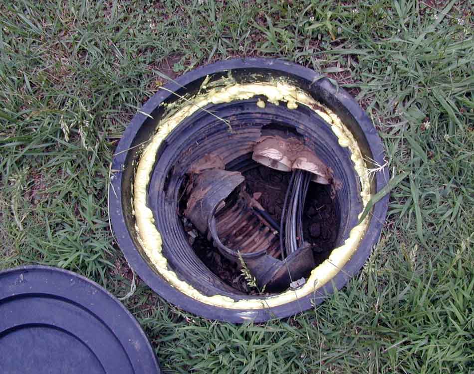
Note the large corrugated drain pipe cut-away T. This pipe runs between the 318-foot tower, about 350 feet away, and the house.
Although barely visible in the picture, there are many 50-ohm Heliax, control, and 75-ohm hardline cables under the pipes. These cables feed other antennas, like receiving antenna systems behind the house area.
The house serves as a collection point for receiving antennas and cables from my 200-foot tower, while most newer antenna towers and feed lines route into the contest barn.
When covered the manhole looks like this:
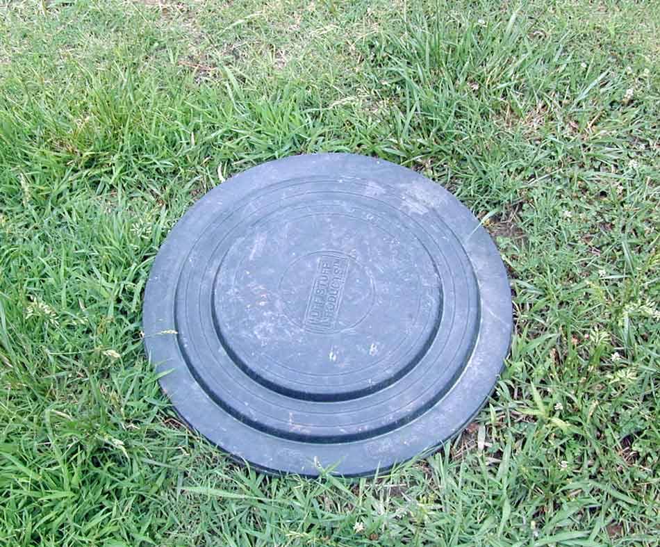
Cover in place hides wiring and keeps out water.
There are other cables arriving at the new building.
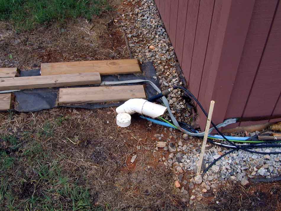
This feed goes to the north end of the property, to the area of the 40 meter foursquare. Several direct burial telephone, control, 50-ohm Heliax, and 75-ohm cables are buried under the conduit. The conduit allows for easy future expansions and protects the directly-buried cables. There is a vertical access point every 100 feet. The little vertical PVC pipe marks an F-11 style direct-burial receiving cable. That F-11 style cable runs 3000-feet to the very rear southwest corner of my property. It is primarily used for experimental or trial receiving antennas. It has access points every 500-feet.
I use an open panel entrance scheme. 2 oz copper G10 double-sided circuit board, mounted on plywood, provides a large groundplane for mounting terminal blocks and switches.
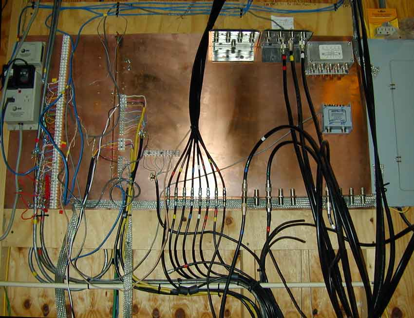
Relay switches above can be quickly patched in, or added in with steering diodes. This flexibility allows creation of rapid customized radio setups in the operating room. Four RG-213/U transmitting antenna cables come down from the operating room. Over sixteen RF trunk cables exit to various towers or antenna locations.
| System | 70 ft with rotor | 315 ft Rohn 65G |
200 ft Rohn 45G |
Rotating tower | Vertical Group | Dipoles |
| Number trunk cables | 2 | 4 | 4 | 3 | 1 | 2 |
All wires are documented on a list:
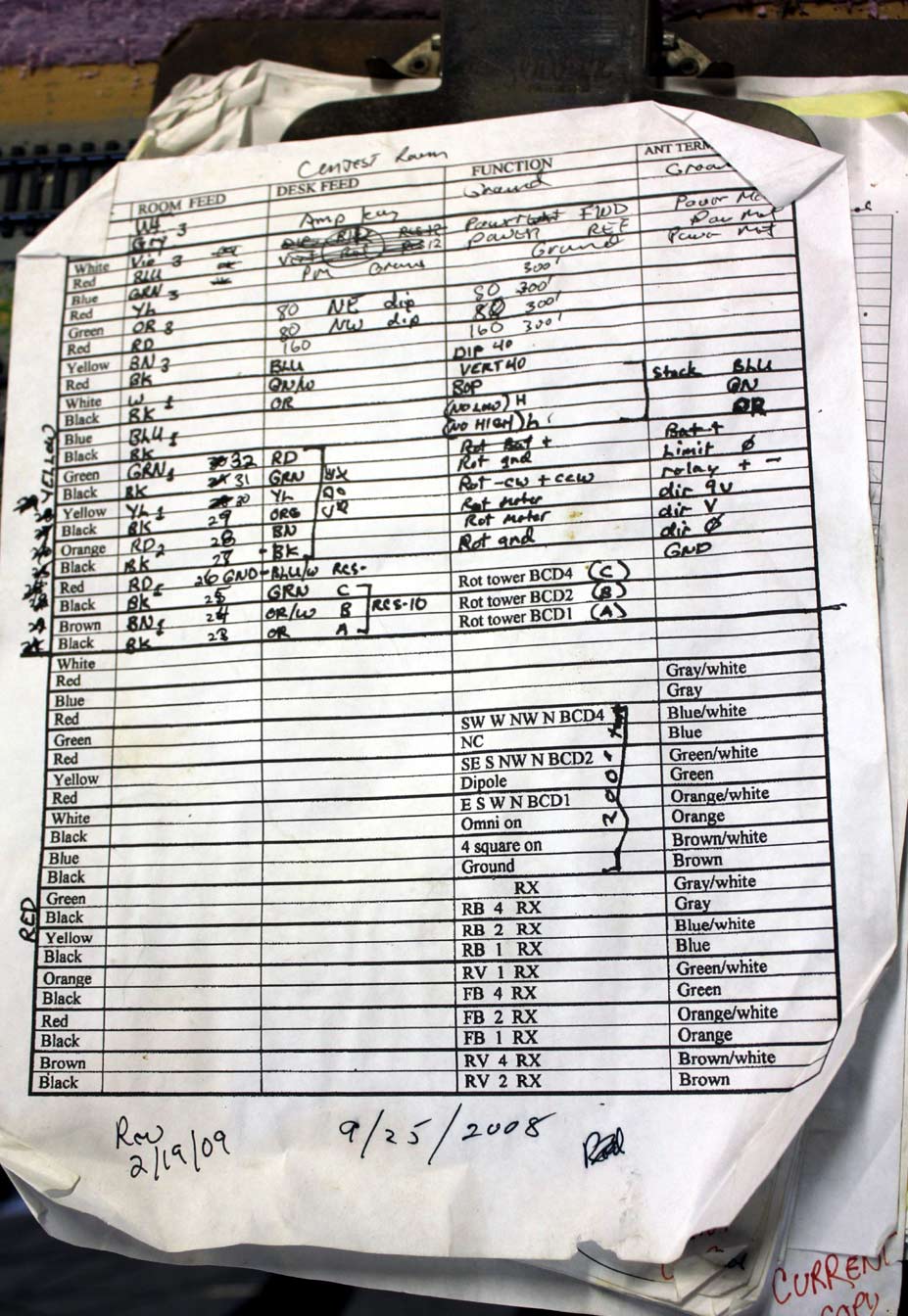
The RCS12 boxes have band decoders inside, lock out wrong-band antennas, and have amplifier relay line lockout.
The transmitting antenna system is being revised to the following system:
W8JI Antenna Matrix 9/12/09
|
Ant |
Tower |
remote relay |
feed+ control line |
local relay |
Sub-local relay |
Control conductors required |
|
160v |
200 |
8 Direction 4sq |
200/.5 2 +(3 BCD) |
2 of 8 |
2 of 4 |
5 (4sq controls) |
|
160 4sq |
|
|
||||
|
160 dip |
300
|
2 of 8 |
300 .625 300 7/8th 3bcd x2 12v x1 |
|
|
7 (2x bcd3 and one +12V) (note:3 spare unlisted ant ports available at tower) |
|
Reserved Spare |
2 of 4 |
|
||||
|
80 Eu |
|
|
||||
|
80 JA |
|
|
||||
|
80 low |
rot |
2 of 8 |
rot .625 x3 |
|
|
12 (note: 3 unlisted spare ant ports available at tower) |
|
80/40 curtain |
Direct barn |
N/A |
N/A |
|
|
0 |
|
40 Yagi |
rot |
|
2 stack, 4 min rotor, 6 bcd |
|
|
Stack 2 wire BCD Rotor 4 conductors min |
|
40 Yagi (+4 extra) |
70 |
RCS-10 |
70 .875 |
|
|
3 (BCD) (4 ant spares) |
|
40 4sq |
barn |
|
vert 7/8th 4sq= 3 |
|
|
3 (4sq direction) |
|
Aux dipole |
barn |
|
|
|
|
0 |
|
20 stack |
200 |
2 of 4 |
bridge .625 bridge .625 |
|
|
12 (2bcd +12v and stack ) Not installed yet. |
|
20 yagi |
rot |
|
|
|
|
|
|
20 yagi |
70 |
|
|
|
|
|
|
15 stack |
200 |
|
2 bcd x3=6ant 6 for stack elv |
|
|
|
|
15 yagi |
rot |
|
|
|
|
|
|
15 yagi |
70 |
|
|
|
|
|
|
Reserved Spare |
300 |
|
|
|
|
|
|
10 stack |
200 |
|
|
|
|
|
|
10 yagi |
rot |
|
|
|
|
|
|
10 yagi |
70 |
|
|
|
|
|
The entire receiving antenna switching matrix was assembled just hours before the first 160-meter contest from the new barn. This switching matrix allows any of four receivers (outputs on top) to connect to any of six antenna groups in any combination. Most antenna groups can select multiple directions at the same time.
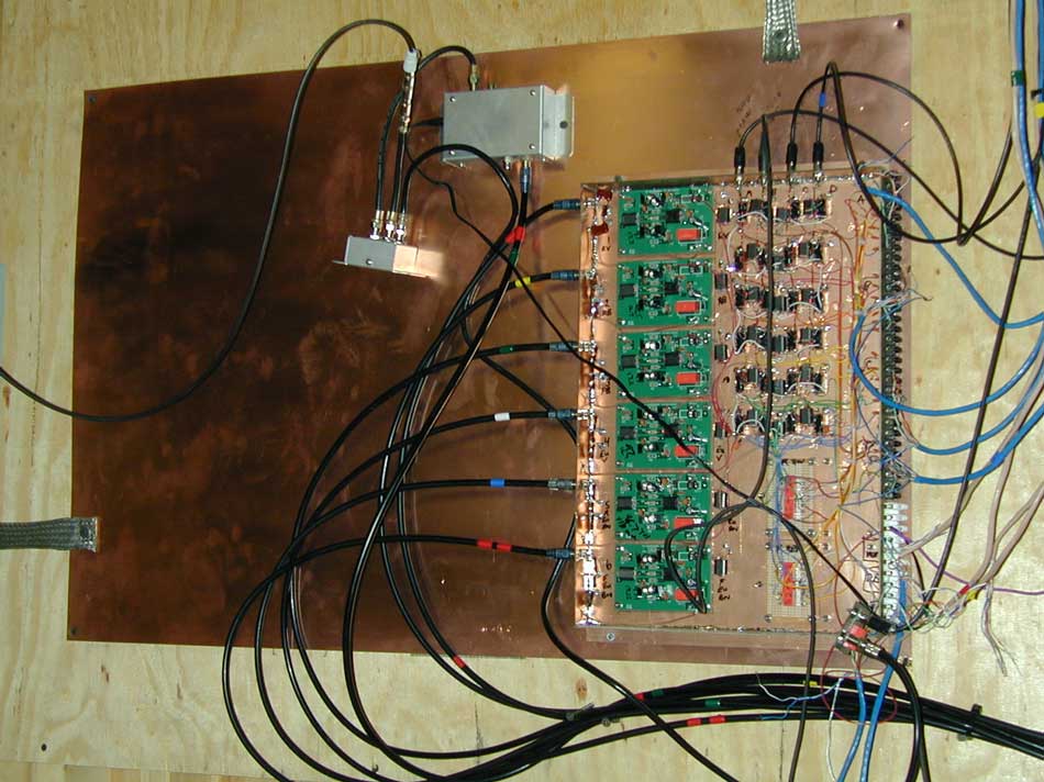
The following are critical construction techniques:
All input connectors mount directly to the input connector wall. Grounds do NOT flow through wires or shield extensions.
Relays are dead-bug style, and use twisted pair wire busses instead of coax. With this construction over the large copper foil PC board backplane, ingress and egress from very strong signals is far into amplifier noise floor.
Cables are color coded by resistor color code sequence, and documented for function and termination on a wire layout list.
One 75-ohm coaxial cable, a CAT-5, and four CAT-3 cables go to each receiver antenna and audio line switch position box. These boxes can be moved around the room to any desk.
Callsign Used: W4AN
Operator: N5OT
Bill Fisher, W4AN, set an all-time CQWW 160 single-op record in 2004 at W8JI. Bill scored 753,867 points, with 1495 QSO's in 56 US/Canada sections and 67 countries. That record was taken away in 2006 when N8T (K3BU at W8LRL) scored 776,424 points with 1464 contacts in 60 US/Canada sections and 72 counties.
In memory of Bill, N5OT wanted to bring the single-op CQ160WW record back from W.Va. to Georgia and W4AN.
The December ARRL 160 is always planned as an equipment and operator warm up session for the January CQWW160. It was pretty tough getting ready for the 2006/7 contests. A heavy work load and contest barn construction delays prevented the new contest station from being ready for the ARRL 160 contest. Bad weather prevented N5OT from operating the ARRL 160 at the old W8JI station, so Mark missed the warm-up where the operator becomes familiar with the station.
I (W8JI) pecked away at the keyboard, mostly sending with a paddle. Despite not being a particularly proficient contest op, I managed 444,528 points, with 1544 QSO's and 126 multipliers, resulting in the top 2006 ARRL 160 CW contest score.
We were still moving equipment into and wiring the new contest barn at the start of the 2007 CQWW160 contest on Friday of the contest. We did not have an amplifier during much of the first few hours, and we experienced several malfunctions as the new station was debugged. One of the worse failures occurred when a loose clamp on the 200-foot omni vertical transmitting antenna caused a catastrophic and non-repairable failure in the 18-year old RCS-8V feeding all 160-meter antennas. This knocked W4AN off the air at a critical hour. When the antennas were restored, another failure forced barefoot operation through Sunday morning peak hours. The best receivers, a pair of stereo diversity phase-locked R4C's with double-balanced diode solid-state mixers, were not available until the second night.
In spite of a few setbacks, Mark piloted the W4AN callsign to 840,486 points with 1706 QSO's in 58 sections and 69 countries. This was enough to soundly move the 2007 CQWW 160 record back to Georgia and the W4AN callsign.
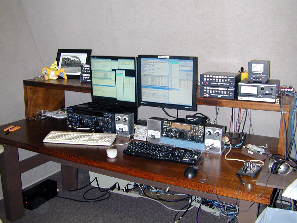
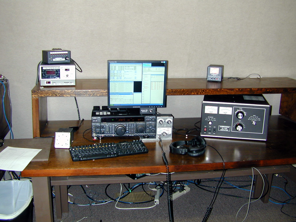
Any operating position can access any antenna on any radio in any direction, and select the audio feed from any receiver or (multiple) receivers independently in each ear with stereo headphone jacks.
On Top
From left to right:
Transmit antenna switches for assist or partner
Monitor for assist or partner
Monitor for run
Run transmit antenna selection
Rotating tower control
Power meter
On main desk level
Left radio FT1000MKV. This radio can transmit, but is interlocked with main radio. We normally do not use it to transmit.
Assist radio receiving antenna and audio selector
Receiving antenna direction control
K3 sub-receiver antenna selector
Elecraft K3
K3 main receiver antenna and audio selector
The receiving antenna boxes can pick up to six different receiving antenna groups or systems. Most groups or systems can pick eight directions. It also has a stereo headphone jack, and any receiver's audio can be placed on either ear. We do NOT use the headphone jacks on radios. The radio speaker lines all feed a transformer-isolated audio buss. This way any headset can listen to any receiver in any ear. See cables and wiring page
The multiplier station is interlocked. It cannot transmit while the run station is on. It can either use its own transmitting antennas, or it can share the transmitting antennas of the run station.
It has an identical receive antenna box. Six antenna groups or systems are available. As with the run station, the mult operator can hear the audio of any receiver in the room in either ear.
The radio here is a modified FT1000MP MKV.
The multiplier station has control of the receive directions for his receiving antennas.
Floor vents below each desk blow cool filtered air up under the desks. This helps keep operators and equipment cool.
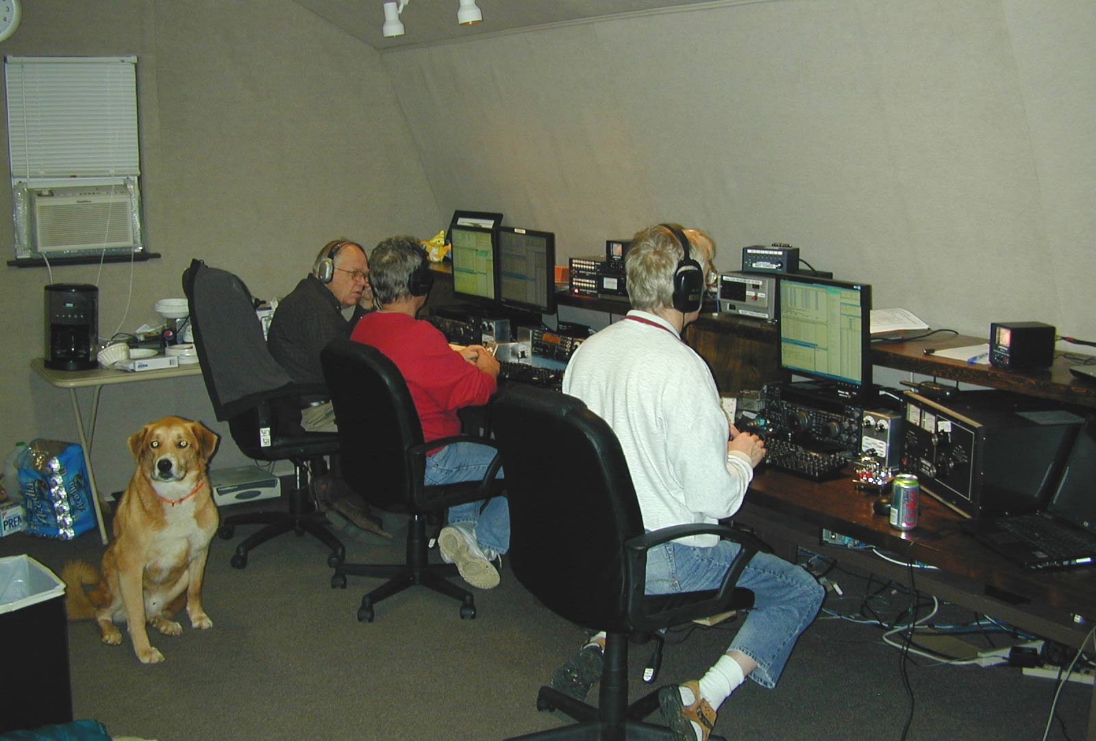
These are the ops from one CQWW 160 CW contest. From left to right:
Hershey, he cleans any spilled snacks up.
John K4BAI
Dan K1TO
Jim VE7ZO
Our station was the first USA to ever score over one million points in any 160 contest, and consistently places first or second place for USA locations. We have set several all time record scores, including 40-meter single-band records. This is despite our inland Georgia location and ~1,000 mile longer path to Europe than northeastern USA stations. Although I'd rather live by the ocean, we do OK with Georgia clay, always in the top one or two place position.
Rule #1 of contesting: Murphy was an Optimist
since 1/30/2007