Station Ground
|
Station Ground |
|
Related Pages: My Contesting and Boatanchor Room Antenna System and my house station
Rumor has station equipment or desk grounds improving reception and transmission, and reducing TVI or RFI. Some even think filters divert harmonics to ground, where the ground absorbs unwanted signals. Like many things heard, there is an element of true results behind scientific folklore. In early radio installations, single-wire feeders were common. Even after WWII, when coaxial cable became common, very few systems used baluns. As a result, early installations frequently had very high levels of RF on station wiring and equipment cabinets. Early equipment did not have a safety ground. USA house wiring was absent the round ground pin, having only a hot and neutral in 110 circuits, and a neutral and two hot leads in 220 applications. Many pieces of gear, since there wasn't a safety ground connection on plugs and cord, depended on a ground rod for safety. Manuals admonished users to "always attach an earth ground" to a ground terminal on equipment. Eventually line voltage increased, as did safety. Line voltage increased to a nominal 117/234 volt with an isolated safety ground (grounded only at the fuse box). Eventually, voltage became 120/240 with typical voltages reaching 125/250 during times of light load. We now have 120/240 in the USA, not 110 or 220 volts. Most equipment is now double insulated, or has a three wire cord with safety ground. What a Station or Desk Ground Can and Cannot DoEffects on Signal Reception or Transmission Even modern RF systems might have installation or design defects. These defects can cause excessive RF current to flow on wires and cables entering the house. Currents like this are called common mode currents, because the current flows without a close-by countering current. For example, a perfectly functioning transmission line has exactly equal and opposite direction currents one each close spaced conductor. This cancels distant radiation, and confines current to the inside of the transmission line. If an antenna or tower system has common-mode current problems, caused by a faulty design or installation, a ground can help reduce common mode noise reaching the antenna. This is really from an antenna flaw, and not from the "reflection of signals". In a case with unwanted common mode currents, a station or equipment ground can also decrease TVI or RFI. The ground might do this by giving unwanted current someplace harmless to flow, keeping RF out of power lines, CATV lines, and telephone lines. A station ground can also keep RF currents out of lossy media, by providing a
low resistance path, if unwanted antenna currents are appearing on station
equipment or cables. A station ground might......
A station ground will NOT.....
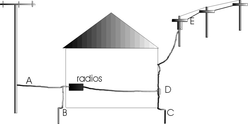
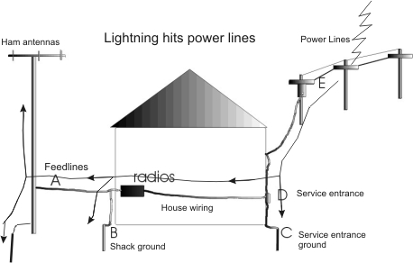
Unless we have a tower that is tall compared to surrounding structures, or unless we are fortunate enough to have underground utilities, lightning most often strikes utility lines. Even when heights of utility lines and towers are comparable, utility lines offer a much wider-area target, so they get hit much more often. Many amateur radio installations have an independent radio-room ground rod installed just outside the radio room. Station ground rods that are not bonded to the power mains ground outside the house can, and often do, increase chances of equipment damage. We should never use an independent ground rod or rods just outside the station as a station safety ground. In this poor but common layout:
Lightning surges flow from E into the service drop and house entrance (D). A very small portion of surge is diverted into the fairly high resistance entrance ground rod (C). The station ground and "electrical mass" of the tower and amateur antennas look like a much better ground than a typical small ground rod at the service entrance. The largest portion of surge flows through house wiring to station equipment, and eventually out to the low impedance antenna system (A) and station ground (B). With common lightning hits on powerlines and powerline surges, good grounds installed at A and B actually increase current flowing through house wiring and radio equipment when the power line gets struck, or if the powerline has a ground fault!
One path for lightning, common with above ground utilities and modest antenna heights, is from powerlines to the house and tower grounds. It can also loop from mains through telephone and cable equipment, or the cable and telephone can also share bringing lightning energy into the house.
Another path for lightning, common with taller towers or underground utilities, is from the tower through equipment to power mains, telephone, and/or CATV lines. Water and gas lines can be included in the path.
Some of us disconnect our antennas, and consider everything in the shack safe. If A is disconnected and B (the station ground rod) remains connected, the radio is still in the lightning path from D to B. Disconnecting the antenna doesn't do much, unless the tower or antenna takes a direct hit or has induced charges from a nearby strike. Disconnecting the antenna is better than nothing, but not by very much. The only way to eliminate more common lightning paths is to disconnect every path through equipment. Unplugging the radio equipment from the power line while disconnecting antennas helps, but there is still significant risk of lighting flowing though equipment on other paths from D or C to A, or from D or C to B unless all external connections are removed from station equipment. The best solution is to bond point C to point B with a much lower impedance path than any other path. B and C should always be bonded together. This is even spelled out in the National Electrical Code. The National Electrical code says," Common grounding is important to ensure an electrically continuous and uninterrupted path to properly dissipate lightning’s harmful electricity. Failure to make all of the required ground system interconnections is a common trouble spot cited in lightning protection system inspections." Also, the desk equipment should be properly connected in the hamshack. Proper radio room cable and power entrance RF grounding also works well for lightning protection! Power lines feeding shack equipment should be grounded to the same entrance point as the antennas. You can see pictures of how I do this at the end of this article. Proper building and tower grounds, and proper wiring methods, provide virtually all equipment lightning protection. The building entrance ground must be tied to the power mains ground. Any additional work, such as improving grounds or adding lightning suppressors, will not mean anything if entrance and mains bonding is incorrect (or does not exist)! Second floor grounds offer a unique (but similar) problem to installations in existing houses where the hamshack and all cables, power wiring, and grounds cannot be at one single entrance point. Click to see typical ground layouts Isolated Ground Leads and Grounds ( Avoiding Ground Loops)Never isolate RF cables on desk equipment with feed line isolators. Our equipment is designed to operate with the equipment tied together with low impedance cable shields. The last thing we ever want are multiple cabinets with differing RF potential on the operating desk. feed line isolators at a minimum belong outside, at the cable entrance. Better yet, they belong at or near the antenna, or the antenna system needs corrected. The only cables required to have ground isolation are audio cables that connect between equipment with different chassis potentials, even when the voltage potentials are relatively small. This is because shields are not several skin depths thick at audio frequencies. Unless a shield is many skin depths thick, common mode current, magnetic fields, or electric fields, will easily move to the cable inside. While newer equipment is 12-volt operated, or has three-wire grounded plugs, older gear often has internal HV supplies and two wire plugs. This equipment must be grounded to a good earth path for safety, otherwise the case of the equipment could rise to more than the highest voltage. For example a blocking capacitor failure in an old radio, with some antenna configurations, could elevate the s chassis to full high voltage. A line bypass capacitor could fail resulting in 120 VAC on the chassis, or a power transformer could short from primary to a grounded secondary winding, adding the secondary voltage to the power line voltage and applying it to the chassis by pushing against the power line. Older equipment also often has power line voltage, sometimes un-fused, on external relay lines. While more modern gear is generally safe, it is best to always bond all gear to a common heavy buss on the operating desk. This buss should be reliably bonded to a good earth path. Any claim you should run isolated grounds to the earth from each piece of gear is not only false, it is also dangerous. Such a silly wiring scheme actually encourages ground loops, as well as decreasing electrical safety for the operator. Some amateur gear is not grounded through a three wire plug. This equipment requires an external safety ground connection to the chassis. This means some stations actually require a station ground buss. This additional ground at the desk will never hurt, and it will never bring lightning in if properly done. It will only make things better, although it often is not necessary. More modern stations
sometimes do not require this
ground because all
of the gear has
three wire plugs or
is 12 volt operated.
If a station buss is
required, place it
at the desk. Every
piece of gear should
connect directly to
that buss as a
common point. That
common point should
run to the station
entrance panel on
one large flashing,
braid, or large
conductor wire. The
station entrance
panel ground must
ground all cable
grounds as they
enter, including
power mains and
telco grounds.
Everything has to be
at the same
potential entering
the room. Do NOT run a separate wire from each piece of gear to the ground rod to avoid "ground loops". Do not use separate ground rods to avoid ground loops. Doing either creates undesired ground loops! This is true at your operating desk, at the entrance, or at the tower. Do NOT use isolators on coaxial lines at the operating position. That is not the place for them, it creates a harmful situation! My Station GroundingMy ground system works. My towers get hit at least once in every major lightning storm, and we have at least a dozen severe lightning storms a year. I never disconnect anything, not even consumer devices, and I have never even lost a sensitive computer modem or delicate VCR to lightning. Tower GroundsThe following is typical of my tower grounds:
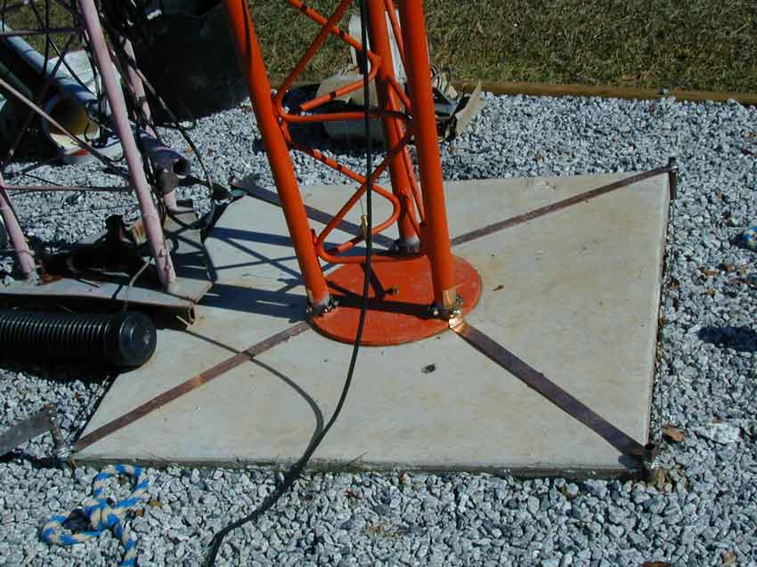
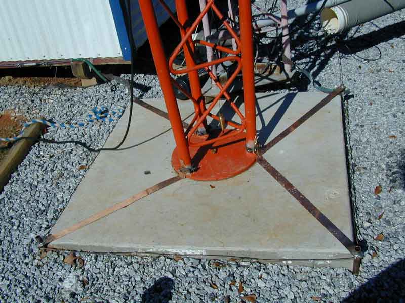
Because this is the point where most lightning current passes, the grounds are wide flashing high temperature silver soldered to the ground rods. This ground does not reduce the chances of a hit. It prevents the cable shields and control wires leaving the tower from being the sole path for lightning currents. in other words, this ground reduces current on wires leaving the tower for the house in the event the tower gets a direct hit, or has substantial charge from a nearby strike.
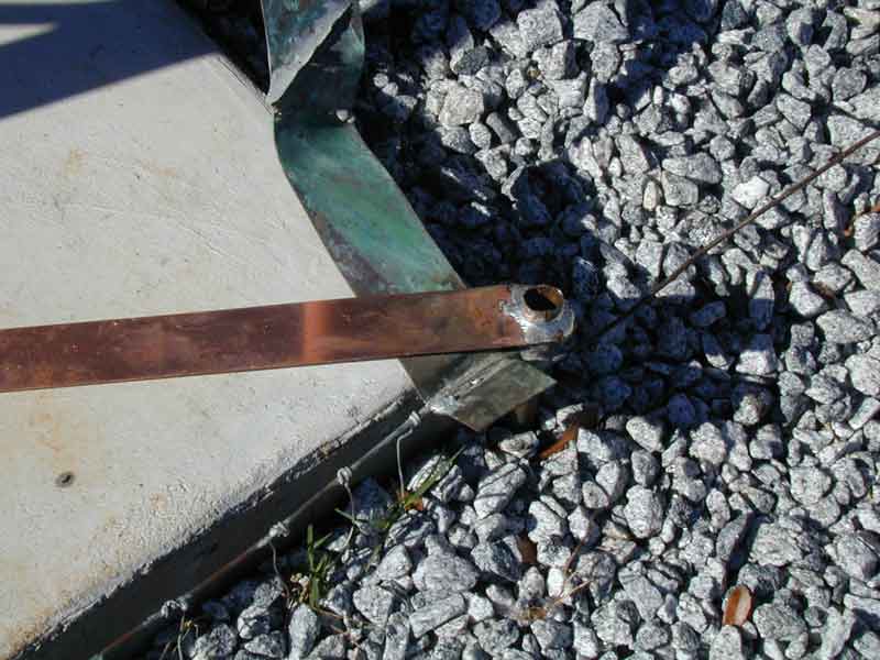
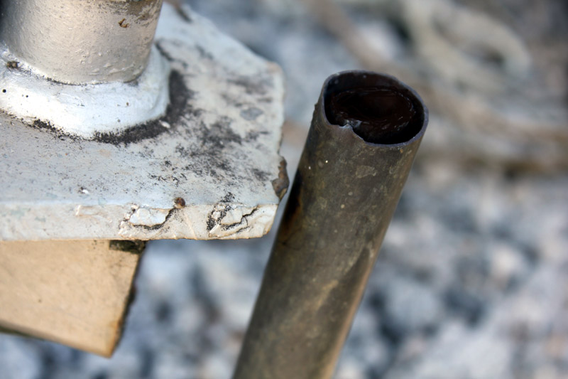
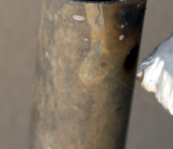
Some say we have to cad weld to have a good connection. That isn't true. We installed many commercial towers using silver solder, and those ground systems are still good after 35 years. The old green patina flashing in the picture was installed in 1998. The older 300-foot tower and its grounding strap has been removed, but during its life the silver soldering survived what must have been hundreds of direct hits. This is high temperature hard silver solder, not plumbing solder. #14 AWG radials are also tightly wrapped and soldered with high temperature silver solder to a number 6 AWG solid buss wire. That buss wire follows the perimeter of the tower pad. I've never had a #16 or larger ground radial fail from lighting hits so long as there are at least ten of them to share current. I use copper pipe for ground rods. To make the connections to the pipe, we use a step bit and blocks of wood to drill a tight hole in the copper flashing. We force the flashing down over the rod. We fold it slightly upwards to cup the joint and fill the resulting depression with high temperature silver solder using a MAP gas torch. You must use high strength high temperature solder, not traditional plumbing solder.
All four corners are grounded to the tower legs. Most of the real work in the ground system is done by the buried radials, not the pipes. An interesting point, I measured the ground currents in my old insulated Rohn 45G 300-foot tower. During an approaching severe thunderstorm, the total corona current was a few hundred milliamperes maximum. unless there is a nearby or a direct strike, current is not that high. Also, the ground system does not "bleed off" and discharge clouds. That is a myth. There is no discharge path to the clouds other than lightning.
Insulated-base Tower ProtectionMy insulated base Rohn 45G tower is protected by a shunt tower to ground (130 feet long), and spark gaps at legs.
Blackened area is from storm arcs.
These are commercial AM broadcast static drain chokes. Like static dissipators, they do not prevent or reduce the number of hits. They do prevent ungrounded towers from "trickle charging" to high voltages.
For amateur service on insulated towers or verticals, amplifier plate chokes work OK. 100 µH is adequate inductance for a 160-meter 1/4 wavelength vertical.
Workshop entrance and ground: Entrance grounds are critical.
This is the entrance ground point of my work shop. The copper pipe has no water, it is actually a ground. It is driven six feet deep, and connects to a buried #8 buss wire running around the outside of the building. Copper flashing ties it to an entrance bulkhead under the rain hood. A number six solid copper wire ties the Telco and alarm ground to the feed line ground. The power mains (breaker box) is also located inside the building at this same point, and it also grounds to this point.
Connection distance between cable entrance, Telco entrance, and antenna cable entrance is virtually zero length.
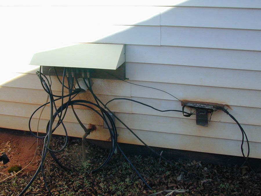
House Ground Receiving antenna, transmitting antenna, and control cable entrance at house:
Because the house was wired without the idea of a radio room, there isn't any way to have cables enter at the same point as the power lines and Telco lines enter the house. Ground conductors and cable shields entering the house are grounded to wide copper flashing. The wide copper flashing connects from my station ground inside the house to the utility company and circuit breaker panel ground. The perimeter of my house has a #6 solid copper ground wire that bonds to the water line, propane tank, TV antenna tower, satellite cable, shack entrance ground, and telephone and electric service ground rod. The wide flashing you see also continues under the house directly to the power mains entrance ground about 30 feet away.
This ensures everything in the house comes up at nearly the same rate during a lightning strike. Large lightning currents do not flow through the house wiring.
House station internal common point ground:
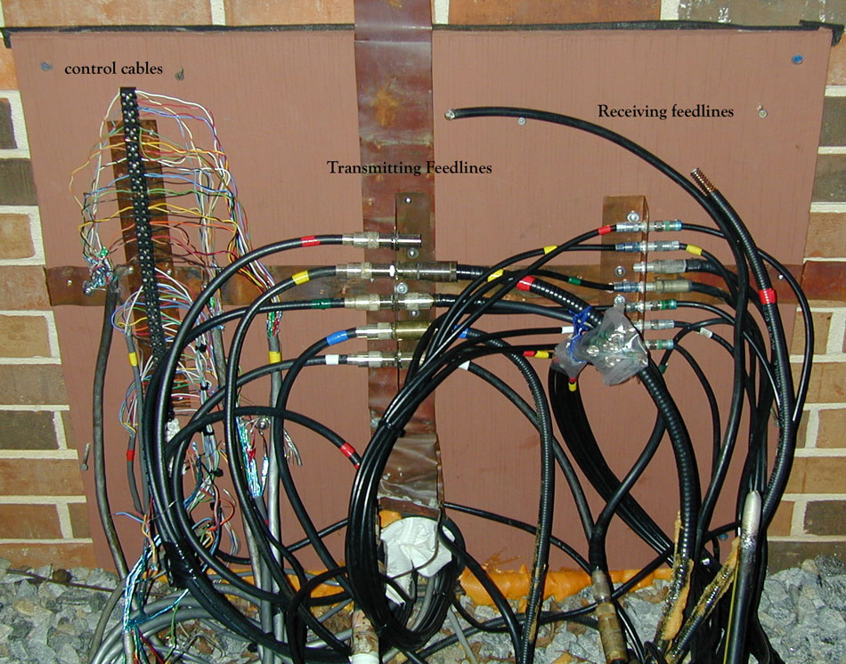
Transmitting cables go to a single point where an 8-position relay cross-over antenna switch routes cables and harmonic suppression filters to various radios. This switch allows any tower's grouped feed line or single antenna feed line to be connected to any radio. Receiver cables are not wired yet, but will go to a common grounded switching matrix.
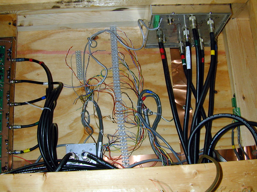
Station power comes from this point:
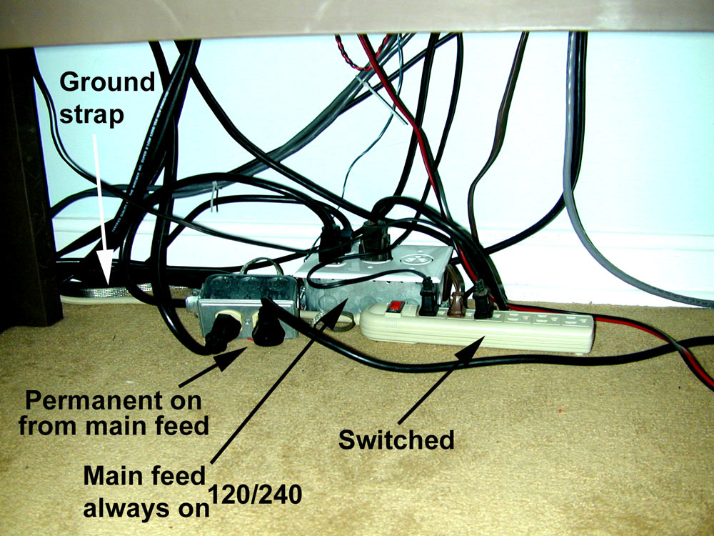
Every ground is bonded to the common point. That common point is bonded to the feed line entrance ground with almost zero lead length. The large relay transfers a 25 kVA generator on-line.
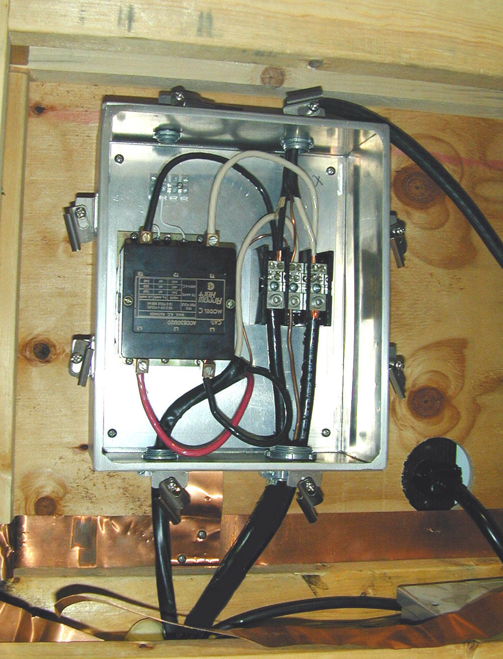
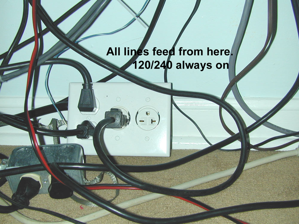
The power distribution to my desk follows:
The white outlet distributes 120/240 volts continuous. The smaller metal outlet branches off to feed a battery backup supply for my computer, VHF/UHF radio, and scanner.
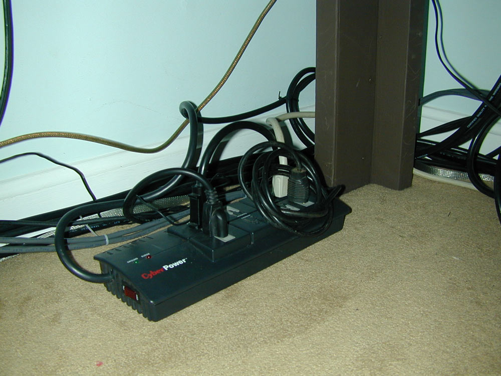
Radios and low power equipment are powered from a master switched outlet:
The following master outlet strip feeds a smaller strip for very low power devices:
Eventually these cables will be dressed up a little more.
Protection is really more about how things are connected than anything else. For more grounding look at my contesting barn's entrance. Also see my Antenna Layout
|