Be sure to read the RFI grounding page
Stations on the second story or higher have a unique grounding problem. Lead lengths to the grounding system are much too long to provide a "low-impedance" RF ground. Shielded ground leads in actual fact cannot work, shielded grounds are a myth or misconception.
With a second story (or worse) station, ground rod or rods (or even buried radials) have very limited effectiveness except on very low frequencies. Still, we should probably have or attempt to have an RF ground when using an antenna feed system with high common mode current, or when using any antenna located close to the operating area.
Electrical safety is a separate issue from radio frequency problems. Electrical safety requires a properly working safety ground path back to the breaker panel, and is more a matter of wire resistance at near dc frequencies.
Lightning safety primarily deals with how entrance cables are routed and bonded to dwelling power mains grounds, and usually or often will require a ground level cable entrance panel.
Curing RFI Upstairs
I'm sure I'm not alone in situations where obtaining a short ground lead is impossible, but first an important fact! Remember this, because it is important! A ground to "earth ground" is never required for RFI mitigation. RFI is NOT caused by the lack of a ground, but rather by a lack of proper bypassing or shielding. RFI is aggravated by poorly installed or designed antenna systems, and sometimes we have no choice in this matter. For example even with all my land and spread out antennas, I still have a tower close to my contest barn. An 80-meter antenna and ten-meter antenna on this tower are only about 80 feet or so from the upstairs contesting room. With 1500 watts, and especially with the high gain 40-foot boom ten-meter antenna pointed right into the radio room, considerable common mode currents can be induced on shack wiring and equipment cabinets.
Installing a ground plane at room level is the most practical way to minimize RF in the above-ground shack. This ground system or more correctly counterpoise can be strips of foil laid under the carpet, a screen, or something under the floor. The conductive wide strips or screen should connect back to a wide station equipment ground buss. Stained-glass hobby suppliers sell adhesive backed copper foil that works very well, and is solderable. As an alternative to copper foil strips, a metallic screen or grid of wires at room level can be used. Whatever is used, be sure the electrical connections between wires are good.
This type of counterpoise system makes the entire room, including the operator, "rise" in voltage to match the equipment chassis voltages. It also disperses or spreads the current and voltage around, reducing intensity of localized electric and magnetic fields.
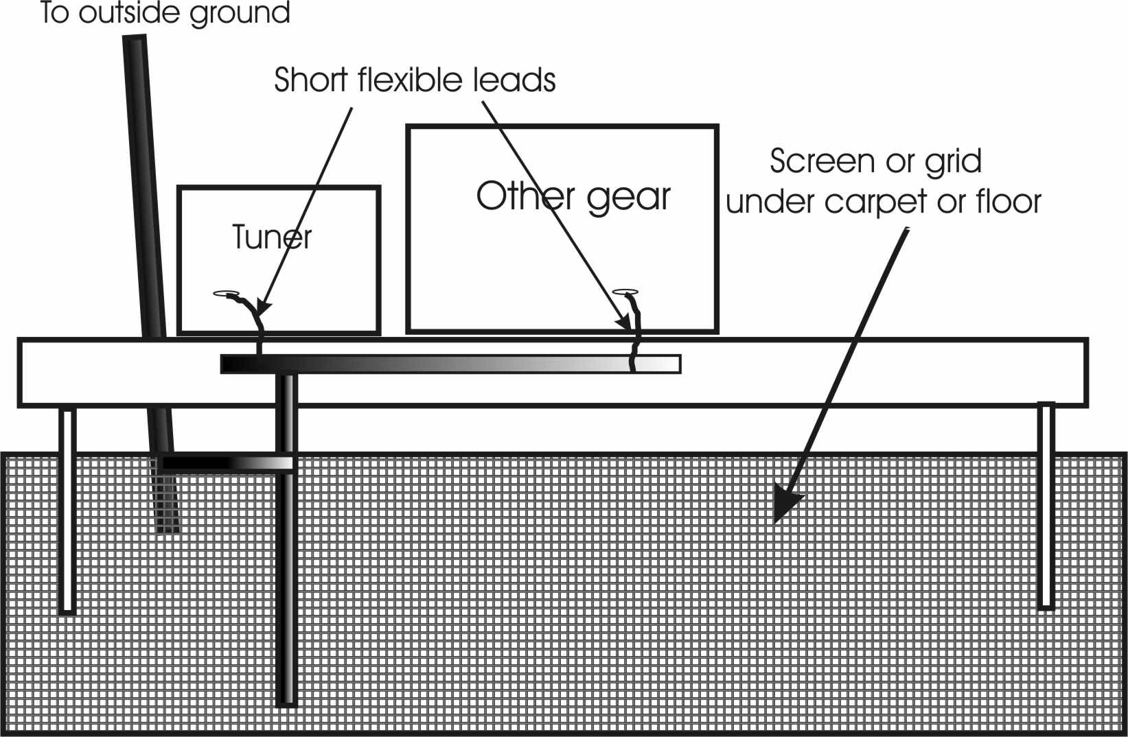
The feed line, if it has common mode problems, should be kept away from the operator and other equipment. The feed line should exit the room with as short a path as possible.
A grid of foil does not need to be too dense. Below 30 MHz, spacing foils one to two feet apart is nearly as good as a solid sheet.
If you can't do that, then sometimes a 1/4 wave counterpoise along the baseboard will work.
The outside ground is only for AC mains safety.
My actual Application
My application is a little bit atypical, because I have quite a few antenna feed lines and radios to deal with. I have a "contest barn" with an upstairs radio room. There is one tower within 75-100 feet of the barn, and the lowest ten meter antenna is not too far above the room level. Even with 1500 watts and a six-element antenna pointed right back at the operating position, there are no RF problems. Here is how I handled RFI (and lightning) problems in my contesting barn:
Entrance panel is bonded to the electrical entrance. This is at ground level. Bonding at this point is primarily for lightning protection.
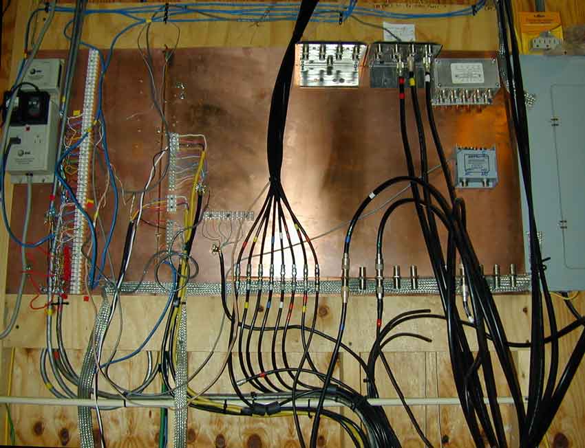
Strapping from the copper wall panel to the entrance panel is short, and I cleaned the paint off the box under the screws and tinned the cover. In addition the copper wall panel extends under the panel edge and is bolted to the breaker panel wall.
The various antenna switches can be quickly patched in for special radio and antenna setups in the operating room. Three contesting transmitting antenna cables and one "boat anchor" transmitting antenna cable come down from the four individual desks in the operating room above. Sixteen or more trunk cables exit to various towers or antenna locations.
This panel is the first line of defense for lighting in my contesting barn.
All cables eventually going upstairs are bundled or parallel after they leave the ground floor entrance common point:
All cables are parallel. This "closes the loop" made by long leads and ensures cables do not have much voltage differential from lightning.
The wide very heavy heavy braiding going upwards is not for lightning. It ties the counterpoise system in the ceiling (contesting room floor) into other grounds.
While flashing would be better, I had thousands of feet of braiding and it was much easier to make bends.
Because I have old boatanchors with two-wire cords, and because I use ground leads as power returns for things like antenna switches and controls, I want good low resistance low frequency paths. Lightning is mitigated at the entrance, not by these leads to the contesting room "counterpoise".
Some cables enter plastic rain gutters that I use as a cable tray. The gutters allow quickly pulling of new cables and keep cables bundled or parallel for lightning and RFI safety. Metal trays or large conduit would have been better yet, but was cost and time prohibitive for me.
Left silver outside tray= shielded control cables (48 pairs)
Left tray= receiving and receive switching
Center bundle= computer and telco
Right tray= transmitting and TX antenna controls
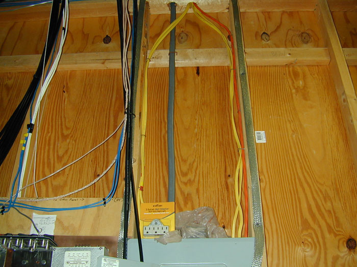
Ground strap. This strap is part of the "grid" of wires that establish a ground below the floor.
The orange and yellow wires are the power line feeds to the radio room
If you look at the lower right corner, you can see the wide ground straps that are being installed to form a closed screen or grid below the radio room's floor. The entire ceiling, which is the floor of the radio room, has braiding that forms a large counterpoise.
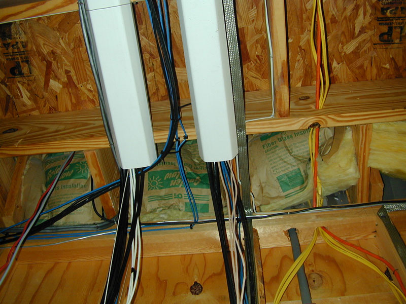
As cables run across ceiling they are all kept close-spaced and parallel. I group them by function, such as receive cables and control cables, high power RF cables, AC power lines, and computer or telephone cables.
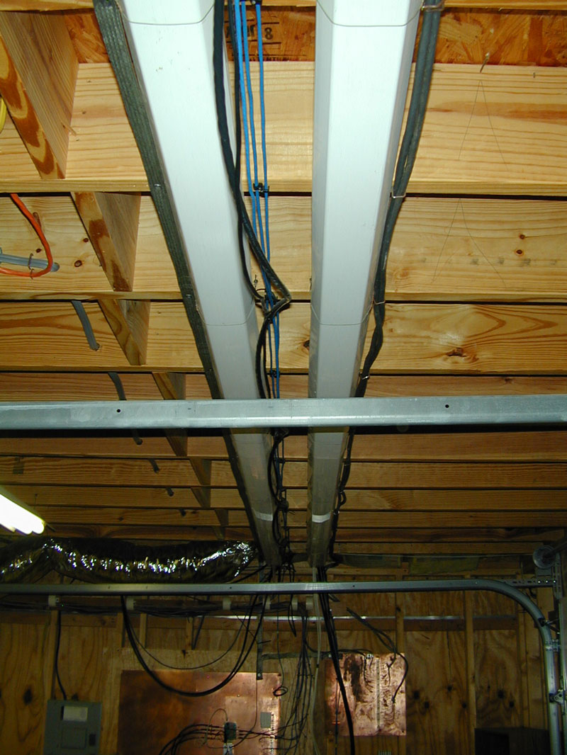
Even the metal flashing that is part of a drip edge for the siding, seen just above the horizontal 2X4, is bonded into the grounding grid at multiple points, as is the frame for the garage door.
Immediately below the desks, I have another common point. This is for amplifier power distribution and receiving antennas. Wiring here is just being installed. Note the very large ground straps that also form a "grid".
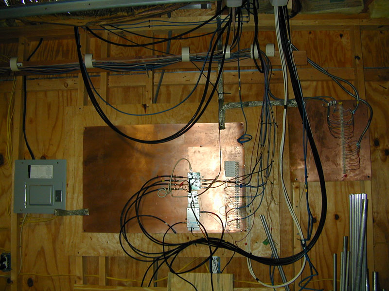
These two wall panels are for receiving antennas and control cables. The breaker panel to the left is 240 volts for seven 15-ampere amplifier outlet feeds.