Related pages:
Station ground lightning and safety
Contest station grounding lightning and safety and entrance wiring
Ground resistance measurements RF ground resistance measurements on small 160 meter antenna
Common Mode Current includes dipole models
Receiving Common Mode Noise shows how lack of a balun can contribute to system noise (it applies to transmitting antennas as well)
RF in the Ham Shack
It is commonly assumed "RF in the shack", interference to consumer devices like telephones or stereos, or even RF feedback or RF burns result from poor operating position equipment grounding. There is also a belief that a good equipment RF ground improves our transmitting signal strength, and the lack of an RF ground causes poor reception. Another popular belief is each piece of desktop equipment needs to have separate leads to a grounding point, so RF doesn't move from the chassis of one piece of gear to the chassis of another through daisy-chained cabinet grounds. Sometimes we read that beads or isolators are recommended on coaxial cables running between pieces of equipment. Like most of us do at one time or another, I strongly believed in RF grounds on my desk.
The beliefs above are actually not true except in very specific (and uncommon) installations! Eventually I learned RF grounds, very often, didn't do anything but mask more significant system problems.
What Causes RF Problems in Equipment?
In a perfectly engineered world, strong RF fields would not bother anything except devices made intentionally responsive to RF energy. Blame for RFI ultimately lies with the device that is not supposed to be affected or controlled by RF being responsive to RF. There are five reasons RF problems appear:
1.) The antenna system has a design, engineering, or installation flaw
2.) The antenna is too close to the operating position
3.) The problem is not RF at all, but is a DC power supply ground loop back into the audio system
4.) Equipment has a design defect
5.) We have poorly installed connectors or defective cables
Why or when is a ham station ground necessary?
Sometimes we set ourselves up for problems without knowing it.
- Antennas with high levels of a phenomena called "common-mode current" can bring a great deal of RF back into the shack via the feed line
- Certain types of equipment with improper enclosure design or improper interconnection design create problems. Examples are poor ground terminal path implementation at the connector's cabinet entrance
- Some equipment is not designed properly on input or output ports, and the poor port electrical design creates or aggravates problems. Example are excessively low voltage threshold on control lines
- At times our antennas are too close to the operating position, causing every wire in the house to become a receiving antenna and a potential source of unwanted strong RF
This is more than an audio line problem. Manufacturers can also put a "pin 1 problem" into power supply and control lead connections. THE ONLY PLACE FOR A SHIELD GROUND, OR 12 volt POWER SUPPLY NEGATIVE LEAD GROUND, IS DIRECTLY TO THE CHASSIS.
What causes equipment cabinets to be hot with RF, a change in noise, a change in RFI, or a change in SWR when a ground is connected or removed from equipment?
If connecting or disconnecting a operating position ground causes a change in noise level, SWR, reception, transmission, RFI, or TVI.....your equipment has significant RF flowing over the wiring or cabinets. This type of unwanted current is called common-mode current . Common-mode current is not flowing inside a cable shield, or flowing as a properly balanced-current in a parallel wire feed line. Common-mode current is like currents causing antenna radiation. Common mode flows on the outside of shields, or appears as an imbalance in phase and/or current level in multiple parallel conductors. Common-mode current explanation.
What sounds like RF feedback usually is RFI, but other things can sound very similar. We should never assume distorted or bad audio, or other anomalies during transmission, are always RF feedback or RF generated problems. An "RFI" problem might be direct current ground loops in station audio wiring, or in control wiring. These unwanted dc currents can cause SSB power supply current load variations, which vary at an audio frequency or CW keying rate, to modulate transmitter audio lines or control lines.
Audio lines routed from one piece of gear to another, if that equipment is not locked to the very same dc or low frequency cabinet potential, should always be grounded through a chassis ground path only at one end of the cable. For example a microphone input normally has a ground inside the radio. Ideally that ground should be at the connector entrance, but often it is located up on some board near an audio preamplifier. If an external device is connected to the mic jack, and that external device grounds the mic shield back to the station ground or power mains safety ground, it will introduce hum into the audio. This is called a ground loop. If the 12V power supply is similarly grounded (as it should be) to the mains safety ground, audio-rate modulation of the 12V supply can be coupled back into the mic input shield. Current flowing on the shield to the radio causes a longitudinal voltage drop along the mic cable, and that voltage will modulate the transmitter. This distortion sounds very much like "RF feedback", but it is an audio shield ground loop issue.
A second problem is poor design of some devices, in particular external audio interface devices. Not only should external systems isolate shield paths with suitable audio isolation transformers, if they contain semiconductors they should employ properly designed RF bypassing. Many devices do their intended audio frequency job very well, but are inadequately designed for use in high RF fields. Devices noted for causing ground loop problems include cheap computer sound card interfaces, and some external station accessories, such as microphone switches.
I have this problem with multiple headsets at multiple operator position, when I do not float the audio lines with isolation transformers.
RF Isolators and Beads on RF Cables
RF isolators and beads on coaxial lines modify common mode impedance on the outside of cable shields. They accomplish this by allowing a voltage difference to appear longitudinally across the bead or choke. In effect, the cable shield going into the isolator or string of beads floats at a different RF potential to ground than the same cable shield exiting.
It is almost never a good thing to have potential
differences across cable shields on a desk full of lower-level lines. The only
thing that can be accomplished is shifting of current from heavy coaxial lines
to smaller lower level signal lines.
Typical transmitters, amplifiers, antenna switches, and antenna tuners do not
create noticeable
RF currents on the outside of shielded cables. Harmful outside currents never appear with properly installed connectors, wiring, and equipment cabinets.
If we have bothersome or significant RF currents in our shacks on the outside of
interconnecting RF cables, we really should learn why the RF is there and
correct the real problem. We should correct the real problem because it is an
abnormal problem that should never appear.

Generally coaxial connectors are bolted to major areas of sheet metal that form one of the cabinet walls.
With connectors properly bolted to a cabinet metal wall, all currents stay inside the enclosure. If there are any outside currents on transmitting cables between cabinets, and we add beads or isolators, we simply shift those currents from cable A to cable B.
As a general rule any currents are either generated outside the desk system, or are a result of poor connector installation or poor cabinet design. On HF or VHF, cabinets do not need to be "RF sealed". As a matter of fact, an arrangement with RF paths closely spaced over a good groundplane can be just as effect as a totally enclosed housing.
The important point is if we do have a problem
with RF outside cables, we should learn why that happens and correct it. The last thing we should do is float shield
ground connections (which is what the outside of the shield provides) between
different pieces of equipment on our desk. The most we can expect from isolating
the outer shield path with isolators or beads is relocation of unwanted currents
to other cables and wires
between gear. Beads over transmitting cables or isolators on RF cables between
major equipment isn't a good idea.
Equipment behavior changes, observed by moving wires around, changing grounds to
the desk ground, or changing outside shield impedances, indicate a problem with
connector mounting, shield connection impedance, or cabinet design. As for
equipment, there are a few cases of terrible cabinets. At least one commercial
antenna tuner has an intentionally insulated cover. Another tuner tuner uses a
single-core 4:1 current balun that forces balanced output lines into significant
voltage unbalance. No one can dispute there are occasional serious errors in
equipment design, but the real fix is correcting the design error.
The correction for those and other errors is not in grounding connections to a
ground buss, or adding isolators or strings of beads. The proper fix is
correcting system defects. Otherwise, when we throw an isolator or beads on
cables, we simply move the problem someplace else in the wiring where it waits
to cause problems in the future.
Isolators have a place in the world of antennas and feed lines outside the Ham
shack. They can be important when a system is neither perfectly balanced
nor perfectly unbalanced. Marconi verticals with less than perfect grounds are
examples of systems operating in the netherworld between perfectly
unbalanced and perfectly balanced, where isolators legitimately help. But in
cases like this, we want isolation that allows voltages to be different along a
section of coaxial cable to be OUTSIDE the house, not inside the house where
noise and devices sensitive to RF live.
Inside the house, we really want all cabinets and device chassis to have the same RF potential. We do not want to isolate cabinets from each other, intentionally allowing them to float to different RF potentials to each other and to ground. If throwing beads or isolators on an RF line inside the shack changes something, that line has a problem that needs fixed or at least needs understood.
The only beads in my shacks on any RF cables are on receiver leads that have phono plugs, because the layout of the plugs and the shield connections are less than ideal. I live with those connections because that is the type of connector used. I understand what the problem is and choose to work around it, and I keep an eye on it.
A shield connection similar to the picture below, with the connector mounted on an insulated or isolated panel, can increase shield leakage by at least 40 dB at 7 MHz.
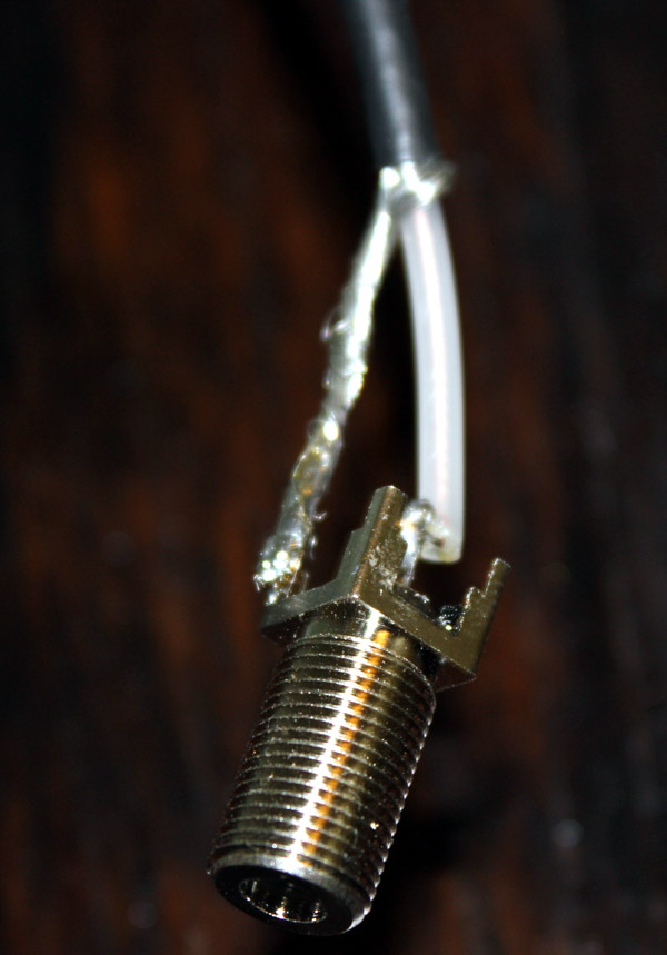
I can't imagine having connections like this on a 100-watt transmitting line,
let alone 1500 watts. Transmitters deserve real connectors mounted properly, and
cabinets with RF integrity at joints. What we do inside the box doesn't mater
much, but ground entrance method is significant.
What causes common-mode current?
Current flows when there is an electrical potential (voltage) difference between two parts of a system, and a conductor between those point to carry current. There are also special currents, without actual electron movement, called displacement currents. Displacement currents flow through capacitor dielectrics, between a vertical or single wire fed antenna and the "ground" for that antenna, or even between a mobile antenna and a car body. Any two things that have capacitance between them can have displacement currents flowing through that capacitance.
Displacement currents commonly complete the current path in open-ended antennas, although all antennas have displacement currents. Displacement currents are the reason an open-ended antenna like a dipole, longwire, or vertical is able to have current flowing out to the antenna end, even though the insulated end just hangs in the air! They are also one of the reasons current tapers in an antenna, instead of being equal through the entire length of the antenna. This displacement current has to somehow get back to the feedpoint, and is a major cause of common-mode currents. There are several other causes, but they involve more easily understood circuit paths.
The amount of current is dependent on path common mode impedance and the source and termination characteristics. This is why some people claim ferrite beads work wonders, and why other people claim the same very beads won't work. Band-aide patches, like peppering a flawed installation with beads to correct a problem caused somewhere else in the system, are very system dependent.
The feed line
If you are not familiar with how coaxial cables work, you might want to look at a simple explanation on this site or one of the ARRL Handbooks.
In order for a conductor (like the outside of the shield) to not have current flow at radio frequencies, it must have the same electrical potential and phase all along the length. If it has a high series impedance (common mode impedance) or if the potential difference along the conductor is low, very little current will flow. As seen in coaxial cable operational descriptions, any coaxial feed line can have unwanted common mode currents.
Does a vertical or longwire present high common mode voltages to the feeder that can cause common mode currents? You bet it does! The only vertical (or longwire) that would not cause such problems is one with a very good or nearly perfect ground system, and that means something that electrically looks or behaves like an infinite groundplane. Even then, the cable must exit below that groundplane to be "shield current free".
Most excessive operating position RF level problems are caused by the antenna system
Bringing a longwire or some other single wire feed system directly into the operating position will create high levels of RF in the station. This is because, unlike two-wire balanced lines or coaxial cables, a single wire feeder has no other terminal or return conductor to "push against" for currents flowing to and from the antenna. Longwires, random wires, inverted L's, true Windom antennas, or any other single wire "feeder" or antenna require a desk RF ground connection. When such antennas or feed lines are brought into the shack, they also bring grounding problems to the operating area. Another troublesome antenna is the OCF (off center fed) dipole. It is an antenna with severe common mode problems, even though it has a two-conductor feeder.
Some verticals are problems for common-mode currents also, because they lack a proper ground. A vertical is most often an end-fed antenna. Sometimes the element is 1/4 wave, at other times 1/2 wave or 5/8th waves long. If we do not use a perfect "zero impedance" ground system, vertical antennas can excite their feed lines with significant common mode current.
An RF ground for house equipment is never required when using properly functioning two-conductor lines such as coaxial cable or open wire transmission lines. With properly operating coaxial or balanced feed lines, the operating position should have minimal RF levels even when a shack or desk ground is totally absent! My present stations do not have RF grounds at the desks or inside the room, as was also true for every one of my stations since the later 1970's. I have used desk-top safety grounds with older gear, specifically older 120V-operated vacuum tube transmitters and receivers (you'll understand why later), but that is always for safety and not for RF grounding.
If you have two-conductor feeders, either in the form of standard coaxial feed lines or balanced transmission lines, and have RF in the shack or see a change in noise level, transmission, reception, TVI, or other problems when a station ground is connected or disconnected, you really have a different problem. If you have RF problems and have good cabling between various pieces of gear, it is probably not a ground connection problem. Your antenna system feed line or other conductors entering the shack probably have significant common mode currents. The sole exception to this is when single wire feeders are brought into the desk area.
Log Periodic Antennas and RFI
One problem I have helped two or three people with is their improper routing of coaxial cables on their e log periodic antennas. In all cases they were trying to cure severe RFI and "hot cabinets" in the radio room with chokes and beads and grounding. The real problem was at the antenna. With the antenna feed corrected, their problems went away without suppression beads in the shack or RF grounds in the Ham shack.
Dipoles
In the case of a dipole antenna, each feedpoint terminal has "voltage to earth". If a perfectly balanced dipole has 100 volts across the feed terminals, the feedpoint would have about 50 volts to an imaginary groundplane bisecting the antenna center.
The current pattern to the left is for a 1/2 wave dipole 1/2 wl above ground, with coaxial feed. You can see the feed line shield has significant current. In this case about 40% of the antenna's maximum current!
We can simulate a choke balun by adding a current source in series with the shield and setting current for zero amperes. The voltage across that current source will indicate the common mode voltage exciting the feed line.

Adding a perfect choke balun, current on the feed line shield goes to zero and the voltage across the choke balun is now found from the source menu:
Current = 1 A. at 0.0 deg.
Impedance = 61.02 - J 0.009274 ohms
Power = 61.02 watts
Source 2 Voltage = 37.42 V. at 173.27 deg.
Current = 0 A. at 0.0 deg.
Impedance is infinite
Power = 0 watts
Source 1 (61 volts) is the actual terminal excitation of the dipole, while source 2 (37.42 volts) is the voltage that would cancel common-mode feed line current. We can see the voltage across the perfect balun is indicated by source 2 as 37 volts. This is slightly more than 1/2 the feedpoint differential voltage. (We could also use a very high impedance load in the feed line of the model and show the same thing.)
This is a substantial amount of shield excitation. It is easy to see how a dipole without a good balun might cause RF problems at the operating desk. We fix this by "grounding the heck out of the station", but the real cause and best cure would be fixing our antenna. by the way, a few turns of coax on an air-core form is not a good balun at all. It takes almost 15 turns 4" in diameter to make a good 40 meter balun, and the impedance is mostly reactance. The choke location has to be carefully planned when using an air-core balun. Depending on cable lengths and balun or choke location, adding an air core balun or choke can even make things worse! If we use an iron core with a high loss tangent, most of the impedance will be a resistance. This will increase common mode isolation over a much wider bandwidth. A high resistance low-Q balun is much better for bandwidth and much less critical for location in the system.
Dipoles, even though balanced antennas, can have problematic common mode currents when fed improperly. Without a balun some feed line lengths can cause problems, while other feed line lengths can actually eliminate need for a balun. One popular balun and unun handbook claims a dipole does not need a balun because the feed line is a very small diameter in wavelengths. That isn't true at all. The author tested the need for a balun while using a 1/4 wavelength vertically handing feed line, a case where his choice of feed line length just happened to eliminate the need for a balun. It was nothing to do with the feed line diameter being small!
There is no universal magic feed line length that minimizes common mode currents in every installation. The length required to minimize common mode varies with feed line routing, grounding, and surroundings. If we have a very specific situation, like a vertical feed line hanging vertically in open air from a dipole center, and that feed line runs straight down to earth and is grounded at earth's surface, we can predict the feed line length to minimize common mode without a balun. The magical length in this specific case is 1/4λ or any odd quarter wavelength of cable length between the antenna feedpoint and ground. Since the primary dielectric between the cable shield and earth or the antenna is air, feed line velocity factor is meaningless! If we inserted a common mode choke right before the ground on the antenna side of the ground, it would maximize common mode problems! We have to be careful throwing parts at a system hoping something will stick.
Verticals with less than infinite groundplanes
Here is a model of a groundplane with four radials:
Balun 80 vertical 1/3/04 7:19:05 PM
--------------- CURRENT DATA ---------------
Frequency = 3.6 MHz.
Wire No. 1: 6.700 (antenna element)
Wire No. 2: 1.359 (This is your feed line or mast)
Wire No. 3: 1.985 (radial)
Wire No. 4: 1.985 (radial)
Wire No. 5: 1.985 (radial)
Wire No. 6: 1.985 (radial)
We can see significant current flows over wire 2, which would be the coax shield, a mast, or both.
There is a trick we can use with Eznec. By inserting an additional source in the mast or feed line and setting current to zero, we can observe the radial common point to earth voltage required across a balun to force current to zero. In this case the voltage across the balun would be:
Current = 0 A. at 0.0 deg.
Impedance is infinite
Amazing isn't it? At 1500 watts the ground common point for the radial system actually wants to have 145.5 volts to earth to prevent current flow along the outside of the shield!! If we elevate the common point to 145.5 volts at 68 degrees phase angle, we now have the following currents at 1500 watts:
Wire No. 2: 0 A (coax shield or mast)
Radials: 1.58 A each (antenna radials)
How many times have we been told four resonant carefully tuned radials make a perfect ground? Obviously any claim four radials form a perfect ground is not true. If it was a perfect ground center point of the radials would be at zero volts. With four radials the antenna is not perfectly unbalanced. Since the antenna is not perfectly unbalanced, some feed line lengths or grounding arrangements will allow appreciable current to flow over the coax shield.
Is it any wonder we have RF problems with some of our antennas?
End-fed Antennas
End-fed antennas, be they so-called "end-fed dipoles", zepps, or longwires all offer a very good chance of having RFI problems. They might require multiple stages of feed line decoupling to reduce in-the-shack RF problems. You can see some examples of problems they create by looking at my page about end fed zepps and other end fed antennas.
Other Systems
Windom antennas produce considerable common-mode because the antenna is neither unbalanced nor balanced. They require special common-mode isolation techniques, such as a very good current balun or a combination of current baluns and other choking devices.
Full-wave loops operated on their fundamental frequency generally don't create excessive common-mode problems, but they can when operated on harmonics.
Eliminating Common Mode Problems
We commonly hear that a few turns of coax on an air core form makes a good balun or device to cure common mode currents and RFI problems. This just isn't true in most cases.
Even if we use enough turns to provide a high reactance, which many suggested baluns of 5 to 10 turns do not, the resulting reactance is generally inductive on lower bands. Depending on the common mode impedance of the system the balun or choke is inserted in, the reactance can do anything from reduce current to greatly increase current. I use ten-to-twenty turn, 4" diameter, air core choke baluns on some of my yagi antennas. I locate them right at the balanced feedpoints, I tape the coax leaving the choke balun to the boom, and I use a barrel connector as a connection point to the feed cables running down the towers. I ground the barrel connector to the antenna boom.
This establishes a very good reference point for common mode impedance. I know the common mode impedance at the connector is reasonably low (because it is grounded to the boom and tower), and I know any series reactance, especially inductance, will greatly decrease common mode currents.
Typical of my Force-12 Yagi baluns
The balun system above works with any Yagi, and it even works when used with dipole antennas. My 160-meter Inverted Vee dipole has a similar balun system, with the connector grounded to the tower.
Below, Outside Entrance Panel
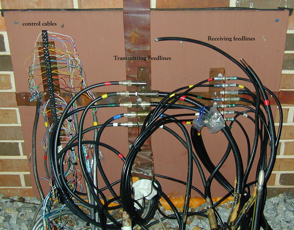
All cable shields are ground to wide copper flashing. This means there is no RF current flowing between shields inside the house.
The wide copper flashing exits under the house directly to the mains entrance ground for safety.
It provides a low impedance shunt to ground for any RF on shields.
Below, Inside Entrance Panel and Common Point
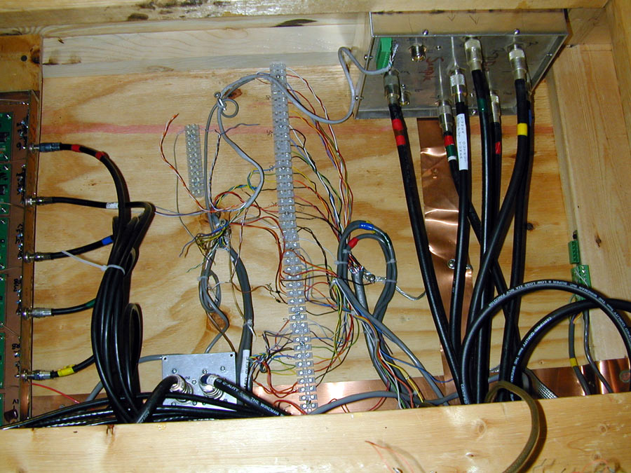
Left to right:
Receiving antenna trunk selection
Control cables
Power SWR sample
Antenna trunk switch
Small green connector is receiving antenna directional control busses
This is double protection. Any current flowing between shields is minimized before reaching the operating desk.
Summary
Most, but not all, RF in the shack problems are caused by poor antenna implementation. It is best to mitigate any problem at the problem's source. Notice the cures above did not talk about the RF grounding quality. The real cure is keeping things at the same potential and keeping unwanted currents outside the house.
Note:
I think the above explanation is a priority. If I left anything out of this or confused you, please let me know. I might not have time to answer e-mails but I will do as much as I can. You can email me at: