Zepp end-fed Antennas
|
Zepp end-fed Antennas |
|
Related Pages: End fed longwire or random wire antenna Groundplane Verticals (they are generally end-fed 1/4 wave radiators)
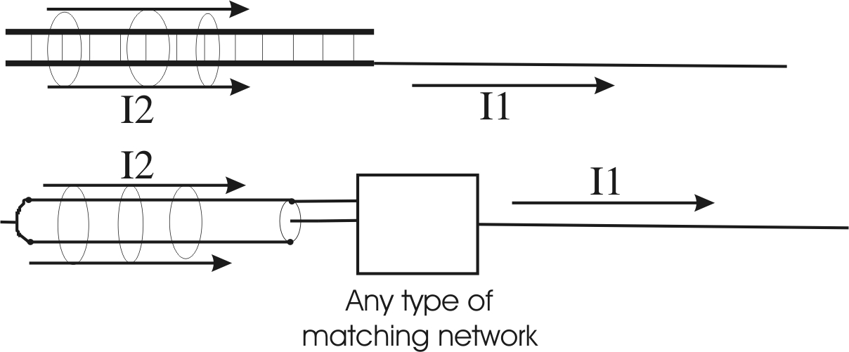
It is important to understand the feed line before discussing end-fed antennas, or antennas like the J-pole or Zepp. feed line BalanceWe often hear a balanced feeder is properly balanced when the feeder has equal currents in each leg. Many articles, test methods, and even some test equipment measures feed line current with independent RF current metering of each conductor, not accounting for phase. Two-conductor feed lines indeed must have equal currents in each conductor to be balanced, although having equal currents, conversely, does not mean the feed line is balanced. As a matter of fact a transmission line with exactly equal currents in each conductor can be perfectly unbalanced, rather than balanced! This is why scalar currents, current measurements without any consideration of phase, are unable to prove the possibility of balance. Equal currents only mean a feed line might be balanced, equal currents do not mean the feed line is balanced. As a matter of fact, while we virtually never hear this mentioned, voltages must also be balanced in an unshielded two-conductor line if we want a balanced line. Each conductor must be balanced not only with equal and opposite currents, it also must be balanced with equal and opposite voltages to the surrounding environment. Without voltage balance, a very strong local electric field can be produced, even while currents are balanced. This is not conjecture, it can easily be demonstrated. Also, voltage imbalance at any point almost always means somewhere else along the line currents is unbalanced. The complete rules for a balanced feeder are on the transmission line theory page. Many articles reach conclusions about feeder balance based on antenna patterns alone. The thought is, a good pattern means good feeder balance. Unfortunately, a good pattern does not mean the system's feed line is properly balanced. Even if imbalance does not distort pattern, imbalance can lead to RF in the shack, and can increase noise levels in the antenna system while receiving. Distant pattern does not confirm proper feed line balance, and is actually a relatively poor way to determine proper feeder operation. Can we end-feed a halfwave antenna, or end-feed any antenna, without a ground or counterpoise?The answer depends on what we want to call a "ground". This simple rule applies to all end-fed antennas, and this rule cannot be broken. The rule is: Current flowing into the antenna's end must be equaled, at that end point, by the same amount of current flowing into a ground or counterpoise of some type. An end-fed antenna must have something attached to the feedpoint that carries the same common-mode current away from the feedpoint as current flowing out onto the antenna! The counterpoise can be accidental and not physically obvious, such as the outside of a coaxial cable's shield, parallel currents on a balanced feed line, or currents on a mast or metallic support. This is true no matter how many series traps, isolating devices or systems, or common mode suppression devices, installed at the feedpoint. This current would be called common mode current, and it always causes close-in, and sometimes even distant, radiation. The counterpoise could also be currents flowing on an intentionally installed radial or counterpoise system, but even an intentional counterpoise results in currents dividing between the intentional counterpoise and accidental paths, like the feed line. Currents divide by how "easy" each path is, or the impedances of the various paths, at the antenna feedpoint. Without a reasonably-sized feedpoint counterpoise, even if we add common-mode chokes at the feedpoint, or use an isolating transformer or network at the feedpoint, voltage across the isolating device increases until the same end-current flows. Even without a direct electrical connection, displacement currents through stray capacitances will cause the same common mode current to flow on the feeder, or perhaps into another unwanted path, at the antenna feedpoint!
This drawing does NOT include differential or normal transmission line currents on the feed line. It only shows the common-mode (I1 and I2), or "radiating currents", in the system. Right at the feedpoint antenna current I1, and common mode transmission line current I2, must always be equal in value and direction at any instant of time. The addition of isolation transformers, baluns, or chokes, will not change this. Only an intentional counterpoise at the feedpoint, in conjunction with adequate isolation between the feeder and counterpoise/antenna junction, can significantly reduce I2 common mode. Elsewhere in the system, away from the point where the single conductor antenna is fed, common-mode (radiating) currents change to other values. Common mode current levels virtually always increase and decrease, in a pattern of peaks and minimums, along conductors. A small current or voltage that seems negligible can become a substantial current or voltage elsewhere in the system. What misterminates the matching stub or feeder on an end-fed antenna?One of the most common arguments we hear is the end of a half-wave antenna has infinite or near infinite impedance, so it does not require a counterpoise or "ground". The end-impedance of a half wave antenna, even at exact resonance, is never infinite. The end-impedance goes through a relatively broad maximum when an antenna is approximately resonant as a half-wave, but the dissipative and/or radiating part of that impedance is limited to a few thousand ohms maximum, even for very thin conductors primarily having low-loss air insulation. The presence of lossy dielectrics, or use of a thicker conductor, reduces impedance further. Because impedance is not infinite, finite voltages and currents are required to apply power to, or extract energy from, the antenna. The antenna end-impedance is always some finite value between a few hundred ohms (for very thick antennas, like large diameter tubing or tower sections) to perhaps several thousand ohms for very thin wire antennas that are up high and in the clear. Because the antenna end-impedance is some finite value, sometimes even lower than we might expect, significant current must be forced into the antenna end. The feed line or stub connection cannot force current up or out into an end-fed antenna without equal current flowing into some form of counterpoise at the feed line or stub connection. Also, without equal load impedances on each conductor, like a symmetrical dipole would have, it becomes impossible to have perfect feeder terminal voltage and current balance. The end-fed antenna is grossly non-symmetrical, or unbalanced. To have a non-radiating feed line, the balanced feed line must have exactly equal and opposite currents and voltages at the feedpoint and all along the line. This means feed line currents in both conductors must flow into some type of similar termination at the antenna feedpoint, otherwise the feed line will radiate. The worse termination imbalance becomes on each feed line or matching stub terminal, the greater unwanted feeder radiation becomes. Why does a problem exist with end-fed antennas?Kirchhoff's Law has been around a long time. It is a perfect unbendable rule, just like Ohm's law. It says, in a roundabout way, current leaving one point must be matched by current entering the same point from some other path or paths. In other words, at any junction, we cannot force current out into something without the same net current coming from something else. This means we cannot force power into a single terminal load. There has to be a return path of some type, even if it is not obvious. The path in a high frequency AC system (like an antenna) does not need to be a direct connection. The path can be through displacement currents (currents through electric fields), but there MUST always be a return path to the source. In the Zepp antenna system, or any end fed half wave, this displacement current must get back to the feed line somehow. If it didn't, it would have no current at the ends. In a normal "push-pull" center fed fed dipole, displacement currents largely (but not totally) flow from one side to the other. This establishes the electric field, and allows current to flow outwards into the wires hanging "open" in space. With an end-fed, current flowing from the stub or feeder out into the end of the radiator must be returned to the opposing conductor of the feed line. This returned current (called displacement current) always equals the common mode current flowing into the antenna end. Without a suitable counterpoise, common mode or radiating currents must flow onto the feed cable or supporting mast. This means, lacking a proper counterpoise and common mode isolation, an accidental (and generally unwanted) feed line or mast common-mode current must exist. In the Zepp or J-pole (both are electrically identical), or with any form of end-fed halfwave, the mast, balanced feed line, or matching stub has to carry common mode, and to some extent must radiate. If the antenna did not have such common mode, it would be impossible to apply power to the antenna. Do we always notice common-mode (imbalance) problems?End-fed antennas always have common-mode currents in some sort of counterpoise, which is the feed line or mast when lacking a suitable counterpoise and isolation at the antenna feedpoint. This does not mean these undesirable currents are always obvious through some sort of terrible problem, or that the antenna will not make contacts, or "make the antenna's owner happy". It means the antenna might not be repeatable or reliable, or have the pattern or performance expected, as a better planned system would have. The benefit is mechanical simplicity and ease of construction, while the cost is repeatable electrical performance. If impedance was extremely high, we could not efficiently transfer energy into the antenna. It would be impossible to design a matching system, especially one with any bandwidth. The end impedance of a resonant half-wave antenna actually ranges from a few hundred to several thousand ohms, depending on conductor diameter and what, even at a distance, is near that conductor. Let's look at a few typical matching systems..... The Open StubThis is the foundation of the J-pole and Zepp antennas. Most of us know a 1/4 wave stub or Q-section can transform impedances. The formula is
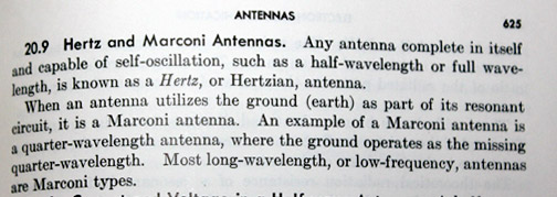
For example, a 400-ohm line with a 3200 ohm load is 400 squared (160,000) over 3200. 160,000 / 3,200 = 50 A 400 ohm Q section will match 50 ohms to 3200 ohms. There is a fast way to do this, since the ratios relate to SWR on the matching section. A 3200 ohm load is a 3200/400 = 8:1 SWR. This means the input has to be an 8:1 SWR on the matching section, which is 400/8=50. Impedance transformation actually relates to SWR on the Q-section. We can use this to understand the end-impedance of the halfwave and counterpoise. Let's assume we have an end-fed 1/2 λ and match it perfectly with 1/4 λ of 450-ohm line. We know the SWR has to be 450/50 = 9:1. From the above exercise we can calculate the TOTAL end impedance seen by the Q-section at the antenna, and that impedance will tell us the SUM of counterpoise and antenna impedances. Since the SWR along the Q-section or stub is 9:1, the sum of antenna and counterpoise impedances is 450 * 9 (SWR) = 4050 ohms! (4050/450=9:1 SWR) The fact we can end-feed a half-wave through a 1/4 λ Q-section of 400-450 ohm line, and obtain a reasonable 50-ohm match, proves antenna end-impedance is some value less than 4000 ohms. The maximum end-impedance of a typical end-fed thin wire antenna is a few thousand ohms at resonance, and the open terminal of the stub has to act like it is connected to a counterpoise. Where is the counterpoise when we do not intentionally have one? The counterpoise is matching stub, and this produces common-mode currents on the Q section. That Q-section ideally has a common-mode (counterpoise) impedance of a few hundred ohms at the antenna end, when the stub is ideal. The antenna and the Q-section each total a few thousand ohms (they are electrically in series), the antenna and Q-section (stub) share in some proportion the task of radiating and receiving signals. How much each contributes depends on the balance and grounding at the tuner or radio end, the length and other attributes of the stub, and the antenna element characteristics. Origination of J-pole and Zepp AntennasThis form of antenna originated as a practical solution to feeding a wire antenna trailing behind a dirigible. This type of antenna, even though the "radiating portion" is 1/2 wavelength and by itself would be self-resonant (making it a Hertz antenna), it has an additional 1/4 wave added. This makes it at least partially a form of Marconi antenna. A Marconi antenna always requires a counterpoise of some form. A Hertz antenna is self-resonant, operating independently of grounds or counterpoises. From an early textbook:
In the Zepp or J-pole antenna is actually 3/4 wave long, with the counterpoise folded back alongside the radiating element. Make no mistake about it, no matter how we feed the antenna or how painstakingly we tune the antenna or stub, the "stub" or feed line will always radiate. Radiation is minimized when the feeder is 1/4λ long, and the antenna element 1/2λ long. To model the real antenna, we must add additional conductors representing the feed line. The model below, which could be a Zepp or J-pole, includes the feed line:
Wire 1 allows a source to be inserted. Wire 2 is half of a 1/4 λ long feed stub Wire 3 is the other 1/4 λ long feed stub conductor Wire 4 is a 1/2 λ element Wire 5 represents the feed line, in this case it is coax 1/4 λ long and open at the radio end The circle is the source The square is a balun. In this case, the balun has an impedance of 1000 +j3000 ohms.
This model would also represent an end-fed Zepp with a grounded tuner and a good balun. Ground currents flowing from the balun to the case of the tuner are 1.5% of peak antenna current, which (especially at low power) is not too bad. When the model includes an imperfect balun or less-than-ideal feed line length, we see things change dramatically. Here is what happens when a worse-case ground path is added to the Zepp or J-pole model:
In this case we find severe common mode currents on wire 5, the feed line. feed line currents causing unwanted feed line radiation are 57% of peak antenna current!!! This system would represent a direct feed with coax, or a tuner on a normal Zepp, with no balun.
Typically, the antenna Hams call Zepps are bent like this:
Bending the antenna will not correct the feeder problems mentioned above!! Everything remains the same. The Zepp (angle between the stub and antenna element) and the J-pole (all in line) are physically different, but electrically identical, systems. Zepp Feeder and Element LengthIdeal element length is 1/2λ, or a low multiple of 1/2λ, such as a full wavelength. This is to ensure the feeder has the highest possible terminating impedance at the antenna, making balance between the open and element connection terminals the best possible. The ideal feeder length for a Zepp antenna is 1/4λ. The second best choice would be 3/4λ long. Maximum feeder radiation, as well as maximum feeder unbalance, occurs when the feeder is 1/2λ long. The chart below shows currents in the feeder or stub of a properly constructed 80-meter Zepp. Pay particular attention to the unbalanced current levels (red column), and where the peak unbalance occurs:
Table above shows 1/4 wavelength stub feeding 1/2 wavelength antenna. Perfect current balun assumed.
On 80 meters, with an 80-meter Zepp (1/4λ feeder stub, 1/2λ element), the system needs equal currents in each conductor at the balun or tuner. We should use a current balun. On 40 meters, the same antenna would have a 1/2λ feeder with a 1λ element. In this case the best feed line balance, and lowest feeder radiation, occurs with a split voltage source. The best balun is a voltage balun. Unfortunately, even the best voltage balun will not suppress fields surrounding the feeder on 40 meters, when the Zepp has a 1/2λ feeder.
The sever unbalance above does not mean the Zepp will not "work" or will not make contacts, but it does mean chances of RF-in-the-shack and feeder radiation is significantly worse on even harmonics of the design band. We can expect the best performance, or the most repeatable performance, on odd-harmonics of the design band. If any antenna using a two-wire feeder is fed properly, there is absolutely no need for a station RF ground. The station RF ground is usually a Band-Aid for an error of some type, often rooted in compromised antenna system design. If an antenna is modeled properly to include feed lines and tuners, the model will show real-world problems that perfect-source models overlook. Conclusions about system behavior often change considerably when tuners and transmission lines are included in models. Eliminating the Stub, and using a Tuned CircuitA second matching method eliminates the stub by using a resonant circuit with a link, or a modification of the link circuit. These antennas are called end-fed halfwaves, or EFHW antennas. Such antennas are really just a modification of the old original Zepp or J-pole antennas. Even though modernized with a feedpoint matching system, they still have all of the Zepp or J-pole feeder common-mode problems. The Double ZeppThis is a poor name. The double Zepp is really just a doublet, or dipole, fed with a balanced line. The line is generally high impedance ladder line, or in some cases, open wire line. Including the feeder and looking at feeder currents demonstrated problems associated with regular amateur radio Zepp antennas, so let's look at the "Double Zepp". Here is the Eznec wire table of the double Zepp: Double Zepp 4/29/2007 3:51:32 PM --------------- WIRES --------------- No. End 1 Coord. (ft) End 2 Coord. (ft) Dia (in) Segs Insulation
Conn. X Y Z Conn. X Y Z Diel C Thk(in)
1 W2E1 0, 0.3, 1 W3E1 0, 0, 1 #14 1 1 0
2 W5E2 0, 0.3, 1 W6E1 0, 0.3, 65 #14 65 1 0
3 W1E2 0, 0, 1 W4E1 0, 0, 65 #14 65 1 0
4 W3E2 0, 0, 65 130, 0, 65 #14 130 1 0
5 GND 0, 0.15, 0 W1E1 0, 0.3, 1 #14 5 1 0
6 W2E2 0, 0.3, 65 -130, 0, 65 #14 130 1 0
Wire 1 allows insertion of the source. It is a jumper across the feed line. Wires 2 and 3 are the balanced feed line. Wires 4 and 6 are 130-foot, forming a 260 foot long "dipole". Wire 5 allows us to test balance The sources:There are two sources in the above model.
The second source, in wire 5, is set for zero amperes. This means the voltage and phase would be the voltage and phase required to produce zero amperes to ground. For the right terminal near the stub bottom, at source 1: Frequency = 3.75 MHz wire 5 Source 2 Voltage = 171.3 V. at -147.94 deg.
Current = 0 A. at 0.0 deg.
Total applied power = 1500 watts
Now watch source 2 as we move wire 5 to the left feeder terminal: Frequency = 3.75 MHz wire 5 Source 2 Voltage = 171.1 V. at 31.79 deg.
Total applied power = 1500 watts
Notice the nearly perfect voltage balance. The voltage difference is only 0.2 volts out of 171 volts. The phase difference is 179.73 degrees, almost perfectly 180 degrees! This is a well-balanced feeder. It will not radiate significantly, and the voltage from each terminal of a tuner to ground would be nearly equal, along with perfectly balanced currents in each leg. The 171 volts is very manageable from a tuner, and it won't matter much if the tuner uses a good voltage balun, or a good current balun. This is a simple system that would be unlikely to produce much RF in the shack. If we do nearfield electric field table around the feed line, we find the electric field out several feet from the transmission line in the house is fairly low. This is with a "perfect" tuner. The Zepp in comparison to the double ZeppNow let's delete one of the wires so we have a traditional amateur Zepp and, in the same test, see what happens with feeder voltages. The antenna model looks like this:
The wire table is: EZNEC+ ver. 4.0 Zepp 4/29/2007 11:10:47 PM --------------- WIRES --------------- No. End 1 Coord. (ft) End 2 Coord. (ft) Dia (in) Segs Insulation
Conn. X Y Z Conn. X Y Z Diel C Thk(in)
1 W2E1 0, 0.3, 1 W3E1 0, 0, 1 #14 1 1 0
2 W5E2 0, 0.3, 1 0, 0.3, 65 #14 65 1 0
3 W1E2 0, 0, 1 W4E1 0, 0, 65 #14 65 1 0
4 W3E2 0, 0, 65 130, 0, 65 #14 130 1 0
5 GND 0, 0.15, 0 W1E1 0, 0.3, 1 #14 3 1 0
Terminal voltages and currents at the stub bottom, on the right terminal of source 1, are: Frequency = 3.75 MHz Right term Current = 8.537 A. at 0.0 deg. Right term Voltage = 131.5 V. at -8.8 deg.
Total applied power = 1500 watts
and on the left terminal: Frequency = 3.75 MHz Left term Current = 7.51 A. at 0.0 deg.
Left term     Voltage = 285.6 V. at -5.45 deg.
              Total applied power = 1500 watts
We see now the phase and amplitude of voltages at each source terminal are not equal. Voltage difference is 154.1 volts, making one feeder terminal have only 46% of the opposing terminal's voltage. Phase difference is only 3.35 degrees, and current in one feed terminal is 88% of the other terminal. Despite the fact current appears reasonably even in both feeder wires near the source, the large unbalance in voltage represents significant localized electric field problems around the feeder. A regular voltage balun, or balanced-voltage tuner like a Johnson Kilowatt Matchbox, while it would work fine with the double-Zepp, would not work well with the true Zepp, so far as RFI and RF-in-the-shack is concerned. Even a good current balun would be taxed by voltage imbalance issues, and we would have to contend with one ampere of RF current flowing out into the cases of station equipment. This is why people have problems with RF-in-the-shack from Zepps, despite what models lacking a feed line or using infinite source isolation might tell us. (By the way if you are uncomfortable using a zero ampere source to measure voltage, you could substitute a very high impedance load in wire 5 to model balun stress.) Another way to determine unbalance, and remember VOLTAGE or phase unbalance is just as harmful as current unbalance to devices near or connected to the feed line, is to run a Near Field table of the electric field. If we do that we will find the end fed Zepp has from a few times to a dozen times or more the electric field levels near the feed line as a center fed double Zepp with about the same feed line impedance and the same power level! In the EZned tabular data for near-field energy, I examined the end-fed Zepp in comparison to a double Zepp. The traditional Zepp had many places where the electric field, 5 feet from the feed line, was ten times or more higher than a center fed balanced double Zepp antenna. The claim by some sources that an end-fed Zepp has minimal radiation and good feed line balance is clearly false. The authors made the fatal mistake of not modeling the near field levels for the same power level and same feed line impedance (conductor to conductor voltage). They also did not check voltage balance, which is just as important for preventing near field problems like RF in the shack. They only looked at one parameter, pattern and current, and concluded if current was balanced or pattern reasonable, the feed line was tame. The problem isn't always far-field pattern, the problem is feed line balance and RFI in the near field.
The ideal 1/2 wave Zepp antenna shows no pattern distortion:
Although high feed line currents appear, they are closely balanced and out-of-phase. This is why many authors conclude feed line radiation is not a problem, and I agree for this specific perfect case! The specific case is the tuner on your desk must have infinite common mode impedance, it must be a perfect ground independent source. The real world adds a few variables, however. Real-world sources are not perfectly ground-independent like sources in modeling programs, real-world antennas are not always 1/2 λ long nearly lossless radiators, and real-world feed lines are not always 1/4 λ long (in common-mode length) on every band. Often the real world is much worse than a model, and rarely is it as good as a model. Let's explore what happens when the real world meets the perfect model! Adding a worse-case ground path to a perfect antenna, we have:
Now we see a slight flattening of the bottom of the pattern. While the pattern does not change much, which some authors might wrongly conclude means no RFI or feeder balance problems, we have the following currents at 500 watts:
Even with the small pattern error, we now have a very significant .75 amperes flowing to earth through station equipment, and perhaps eventually the operator (RF burns). This is with an ideal length Zepp or EFHW antenna, and a typical wrong length antenna feed. Pattern alone does not prove proper feeder operation, and balanced currents at one point do not prove freedom from feeder radiation. To minimize radiation from the Zepp, and to minimize RF in the shack, the feeder or stub should be an odd multiple of 1/4 wavelength long. The element should be a halfwave, or a multiple of 1/2 wavelength, long. The tuner or coaxial feed line should have a good common-mode isolating device, like a current balun, at the interface to the stub. Most of all remember, pattern does not prove balance. The J-Pole
This page has
|