End-fed vertical j-pole and horizontal zepp I-max 2000 vertical
Assuming losses in the reference antenna or the antenna used as a standard
are minimal, all antennas obtain gain through pattern change. As the applied
power being converted to electromagnetic radiation is confined to or focused
into a narrower spatial volume or area, the power density increases.
This is much like squeezing a sealed balloon. The fixed mass of air inside the
balloon represents applied power, while the balloon's extension represents
signal level or gain. For a given air mass, if we want to make it look like we
have more mass, we have to squeeze the balloon so the air moves into the target
area.
Antennas are the same way. The antenna cannot create more power or
energy. It can "leak" and waste energy as heat, but it can only focus or
concentrate the transmitter power it is given by not sending radiation in
unwanted directions. Some antennas claim to increase gain through radiation
resistance changes, or through some magical length. This is, to use a polite
word, bologna!
Always keep this in mind! A particular antenna only has
"gain" over a reference when the reference antenna has significantly more loss
than the particular antenna being considered, or the reference antenna has a
broader pattern.
Image antennas, properly used, are a powerful tool. Image antennas explain how ground reflections influence pattern.
Antenna patterns are created by interference between radiation sources. The effect of this interference is described through pattern multiplication, where multiple radiation source fields add or subtract. Ground effects can be described by splitting power and applying the split to a second (or even more) imaginary antenna. Radiation fields are vector multilied, considering both level and phase. This is pattern multiplication. It is important to remember the image antenna is not real, and the current is NOT actually at the location and depth being used. The current is really spread all around, and the image is just a tool to represent the overall surface current's effect.
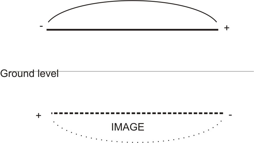
Let's consider a horizontal dipole over perfect ground. Earth below and
extending a distance out from the antenna has induced currents. These currents,
like all time-varying currents, cause EM radiation.
The image antenna for a
dipole over perfect earth is a dipole at the same distance below :
That image isn't an actual current or dipole at the position of the image
antenna. The image antenna just represents all of the currents induced in the
ground all around the antenna. Ground currents all around the antenna
"make" the image work.
The "image" is a tool for understanding
the earth's effect on patterns. Since the image is 180 degrees out-of-phase with
the antenna and effectively the same distance below ground as the antenna is
above ground, it becomes obvious there will be a null along the ground with a
horizontally polarized antenna. The closer the antenna is to ground, the closer
the source and image become, and more pronounced the null along the ground.
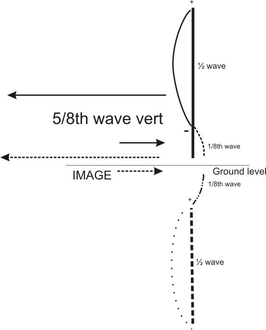
The 5/8th wave is a great antenna misunderstanding example. Everywhere we
look, everything tells us the 5/8th wave has 3dB gain. It is just broadly
accepted, often without a moment's thought, that a 5/8th wave has 3 dB gain.
Nobody questions gain over what reference and under what condition.
The
5/8th wave vertical started life in AM broadcast band installations. The "3dB
gain" was a rounding off of the theoretical gain over a 1/4 wave vertical, when
both were installed over flat, infinitely conducting perfect grounds. the 3dB is
not gain over a 1/2 wave end fed vertical or a 1/2 wave vertical dipole, ~3dB is
the gain over a 1/4 wave vertical when both have infinite flat groundplanes!
Let's look at why this occurs using image antennas.
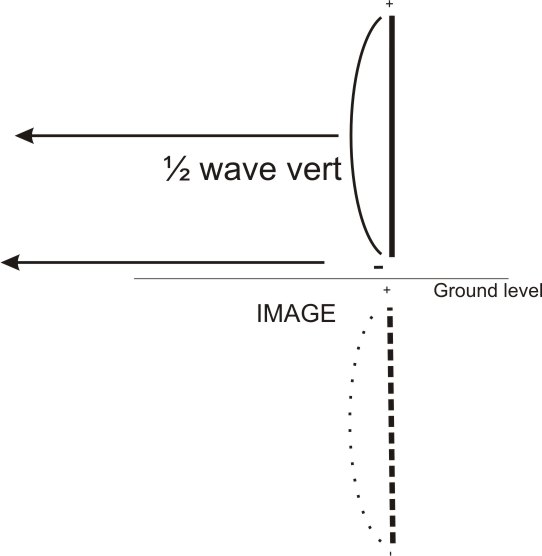
Horizontally polarized antennas have reversed images, vertically polarized antennas copy the same phase.
Groundplane Antennas and common mode
We often hear a groundplane only needs two or four radials to prevent feed line radiation. That isn't true. Years ago when I was designing a commercial antenna for lower VHF, I discovered significant SWR changes in a four-radial groundplane as I altered the feed line length. There was also significant pattern distortion.
Here is the freespace pattern of a 1/4 wl groundplane antenna with four radials without proper feed line decoupling:
Significant common mode current exists on the feed line in the groundplane antenna. Common mode current is nearly 1 ampere with 2.5 amperes at the antenna element (500 watts applied). To behave properly, a 1/4-wave groundplane with four radials actually needs a "current balun" or some other form of feed line and mast decoupling.
The pattern distortion is caused by feed line common-mode current. If you think this is bad, imagine what happens with an end-fed antenna (even a 1/2 wave antenna) and NO radials! In that case all of the antenna current flows over the feed line shield! Many antenna designs actually use the feed line and mast radiation that others dismiss as "insignificant" to increase antenna gain. In some cases, the antenna designers really don't even understand what they did to create a "magic" antenna.
Here is the same 1/4 wl groundplane, with radials and radial ground connection insulated from the mast, with a feedpoint "feed line choke" of moderately high impedance (3000 ohms):
In this case feed line currents are under .4 amperes, and antenna current increases to 3 amperes.
The pattern is much cleaner and more like what we expect from a groundplane far above earth. The antenna, even with a good isolator, still needs more work. The system needs a ground on the "unbalanced" side of the isolator (the station side) to be 100% effective. (This is why I also ground the unbalanced side of Yagi baluns to the antenna's boom. A coil of coax hanging in the air is probably not good enough without a shield ground on the station side of the balun.)
With a perfect balun and optimum de-coupling (a few extra radials below the balun or an extra-ordinary balun), the pattern looks like this:

This is the ideal pattern of a 1/4 wl groundplane. Despite what we might think, it takes extraordinary care to obtain an ideal pattern. We often assume we have this pattern, because we model antennas without the feed line or mast included in the model!
To obtain this pattern, I had to:
Use a good balun just below the radial tip level
Ground the feed line shortly below the balun to a small groundplane
Slope the radials downwards at 75 degree angle
It is possible to accomplish this in the real world. All we need to do is insulate the radials from the mast or tower, use a feed line isolator, slope the radials downwards, and ground the shield to a reasonable RF ground on the station side of the isolation device.
We often assume we don't have a problem with common mode current upsetting antenna pattern because we have four radials. We can find numerous articles that ignore the feed line, and "pretend there isn't common mode current on the feed line. Some articles even claim the groundplane antenna only needs one or two radials!! This happens because the person who modeled the antenna never included the mast or feed line. This eliminates the real-world problem through an omission in the model, there can't be common mode current and pattern distortion from the mast and feed line if the antenna "hangs in space" without a feed line or mast.
If an antenna model does not include the feed line, losses in the feed line, or imperfections in the source it much more likely than not is a flawed model. The real-world antenna often will be much different if the model ignores the feed line and mast.