| Many articles reach conclusions about feeder balance based on antenna patterns alone. The thought is, a good pattern means good feeder balance. Unfortunately, a good pattern does not mean the system's feed line is properly balanced. Even if imbalance does not distort pattern, imbalance can lead to RF in the shack, and can increase noise levels in the antenna system while receiving. Distant pattern does not confirm proper feed line balance, and is actually a relatively poor way to determine proper feeder operation. |
Related pages Skin Depth Common Mode Current
We all know a traditional transmission line system appears like this:
Standard coaxial transmission lines. When this type of line is working without unwanted radiation, all currents are inside the line. The outside world is isolated from the inside of the cable by the skin depth of the shield. Voltage from the shield to "ground", or the environment around the line, ideally is zero.
Balanced two-wire transmission line. In a balanced line, each conductor carries equal and opposite currents (just like in coax) but each conductor has equal and opposite voltages to ground or the environment around the line.
Twisted pair is the same, or similar to, a balanced line.
Fig 1.
In each of the lines above, the feed line will not radiate or produce substantial electric or magnetic fields external to the immediate area of the feed line. The lack of external fields, even at a very small distances, is rooted in three conditions:
1.) All outgoing currents on one conductor are matched by equal level and exactly opposite phase currents on a return conductor at any given point along the line. This causes an equal and opposite magnetic field along each conductor. The opposing magnetic fields, caused by equal currents flowing opposite directions at any instant of time, cancel. This prevents the transmission line currents from creating magnetic fields outside the general area of the two conductors.
2.) All voltages from each conductor of the line to the outside environment surrounding the line are either contained within the coaxial cable shield, or in a balanced line conductor voltages are exactly equal and opposite to the environment around the line.
3.) The vector product of differential current flowing in conductors, and voltage between line conductors at any point along the line, always equals the power transmitted in transmission line mode.
Number three above is very important. Two and three indicate a TEM, or transverse electromagnetic wave. To understand this, think about how your rig connects to your feed line. Everyone knows the alternating current coming from our transmitters have voltage across the output jack. Our transmitters also supply current. At any instant of time when energy is being transferred to the load ((except when zero is being crossed)) the voltage polarity of the two conductors is of opposite signs. Except for zero crossing or when the transmitter is off, the potential difference is always there. The vector product of voltage across the line and current flowing through the line always equals applied power.
The conditions above are required to support energy flow through a transmission line. That mode is called TEM mode, or transverse electromagnetic mode. All two conductor transmission lines, either coaxial or balanced, transfer energy through the line by TEM mode.
Here is what Edward Jordan and Keith Balmain said about TEM mode operation of transmission lines in the classic Prentice-Hall Electrical Engineering Series textbook "Electromagnetic Waves and Radiating Systems":
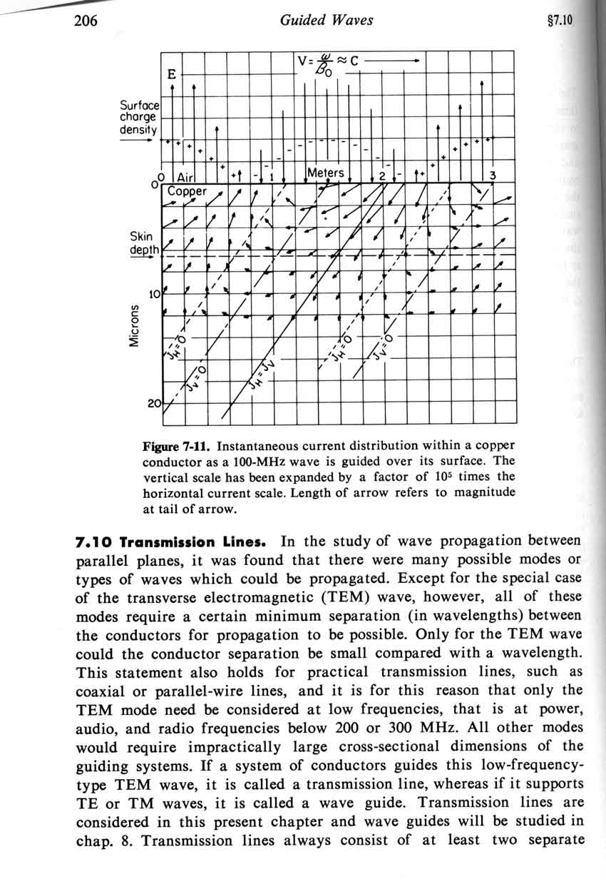
To make a long story short, classic transmission line theory (called "ordinary transmission line theory" in the text above) requires a transverse electromagnetic wave to be launched from one end of the two parallel conductors forming our transmission line. If we do not do that, we simply have two parallel conductors magnetically and electrically coupled. Energy will not be confined to the "transmission line", and can radiate out into the surroundings freely. This is a very important distinction when dealing with feed lines and antennas! When a line is operating only in transmission line mode (transverse electromagnetic mode), we can sleeve the line with ferrites and properties inside the line do not change. The electrical length inside the line does not change and losses inside the line do not change. This occurs because energy in a two-conductor transmission line is transferred via TEM mode; fields are confined to the general area between or around the conductors. Except for extremely low leakage levels caused by slight flaws in the lines, signals don't leak in and signals don't leak out when we have a transmission line operated in transmission line mode.
Unbalanced lines (coaxial cables) actually have equal and opposite currents in the shield and center conductor at any place along the transmission line. So do balanced lines. This leaves us with a question. What makes one line or system balanced and the other unbalanced? Currents behave the same way and are always balanced in a properly working transmission line, its source, or its load regardless of line type, so what's the difference?
The thing separating balanced from unbalanced lines or systems, including antenna feedpoints, is voltage from each conductor or terminal with respect to a physical or imaginary reference point representing the world around the source, feed line, or load. In the case where the feed line does not radiate both systems have equal and opposite currents at every point. These points include the source, the entire length of transmission line, and the load. It is the voltage that actually makes sources or loads "balanced" or "unbalanced", and the containment of fields inside a shield that causes a coaxial transmission line to be considered "unbalanced".'
We often hear a balanced feeder is properly balanced when the feeder has equal currents in each leg. Many articles, test methods, and even some test equipment measures feed line current with independent RF current metering of each conductor, not accounting for phase. Two-conductor feed lines must have equal currents in each conductor to be balanced, but having equal currents, conversely, does not mean the feed line is balanced. As a matter of fact a transmission line with exactly equal currents in each conductor can be perfectly unbalanced, rather than balanced! Equal currents only mean a feed line might be balanced, equal currents do not mean the feed line is balanced. The complete rules for a balanced feeder, referring to the drawing below, are:
Current not only has to be equal in both conductors at all points in the system, current also has to be exactly out-of-phase in opposing conductors. We must measure phase, or at least the vector difference in currents, or we cannot be sure current is balanced. Even if we measure phase and level, we can still have a large voltage imbalance, and voltage imbalance can cause strong external electric fields. Unless all conditions above are met, the feed line could be a source of unwanted local or distant energy. Even if it does not distort pattern, imbalance can lead to RF in the shack, and can increase noise levels in the antenna system while receiving. Distant pattern
We can make a transmission line become a conventional radiating conductor if we apply energy in a non-TEM mode. This can be useful when we wish to use a feed line as an antenna or as a conventional conductor. When we excite a cable like this, the cable freely radiates:
or like this:
All of the situations immediately above cause common-mode problems. This is because even if the equal current rule is met, the line violates equal and opposite voltage rules.
When imperfectly excited, things outside the line influence transmission through the feed line. Adding a ferrite core will add loss and modify the differential impedance of the line, changing SWR. This is true even when currents are equal in the two conductors, and can even be true when currents are equal and opposite, as long as the line was excited from end-to-end!
The key to having a line behave like a transmission line is feeding it differentially at one end, and not applying voltage across the length of one or both conductors.
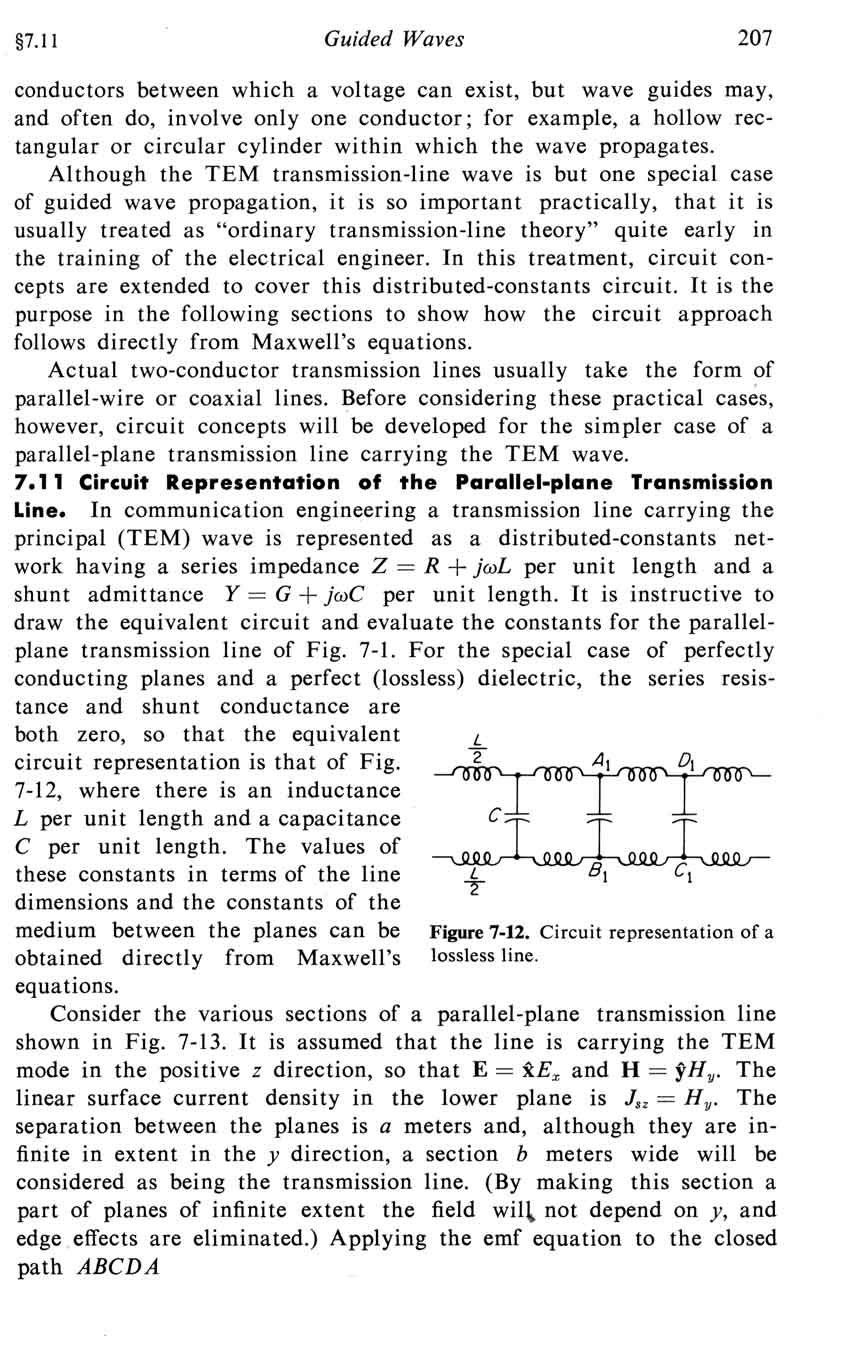
This is a transmission line as we generally know it, and as dozens of reputable engineering textbooks define it:
The above configuration shows a direct wire connection from source to load, and cannot transform voltage, current, or impedance based on turns ratio. This fits the definition of classic transmission line, which requires TEM mode in coaxial or parallel wire lines. Jordan and Balmain cover this extensively in "Electromagnetic Waves and Radiating Systems" (Guided Waves, p215, 2nd edition). Kraus also covers this in "Antennas" in various sections dealing with transmission lines and wave propagation, as does Terman in his "Radio Engineers Handbook" Circuit Theory chapter under the subheading "Transmission Lines".
Most engineering text I have clearly state parallel conductor transmission lines employ TEM mode of energy transfer. If not, they are not considered transmission lines.
Parallel or concentric conductors (coaxial conductors) in non-TEM mode have two major applications, antennas and transformers. Antennas include (but are not limited to):
See Lenz's Law
since 7/1/2005