Common Mode Current (some practicality to lightning)
Station ground lightning and safety
Contest station grounding lightning and safety and entrance wiring
RF In Station Equipment (mostly RF related)
Long wire antenna random wire (RF related)
Ground resistance measurements RF ground resistance measurements on small 160 meter antenna (RF related)
Small antennas and radiation resistance radiation resistance (RF related)
Corrections to confusing text made on July 21, 2011
Updated 6/26/2020
People claim there isn't anything that can be done to prevent lighting damage. This is often used as an excuse to do nothing at all, other than a complete disconnect during storms. While nothing is 100% certain, installations near 100% are quite possible with a little work and care. Since 1998, my station has been connected with some equipment active 24 hours a day, every day of the year. I have several towers between 50 feet and 318-ft tall, with taller towers being struck in nearly every significant local thunderstorm. I also have miles of wire and cables in receiving arrays, spread out over 100 acres.
My station never has significant lightning damage inside buildings to consumer electronics, modems, security systems, or radio gear. Damage has been confined to outdoor antennas and hardware.
Even a modest ground system, when things are done correctly and carefully, will greatly increase lighting immunity. An abundance of commercial grounding specifications exist, but they are either too costly or physically impossible to install in a residential hobby installation. Hams (amateur radio operators) and CB radio operators almost always cannot have ideal grounds, but with care and planning very safe systems can be installed for minimal cost.
Trouble spots are usually caused by not following simple rules.
Poor but Commonly Used
The most severe and frequent damage is normally not caused by a voltage difference between each conductor in a multiple wire cable, but from those conductor groups or bundles to other conductor groups or bundles. Nearly all severe lightning damage is caused by lightning currents flowing through the house wiring as common mode current.
This first example has severe ground loops. It is a danger for many reasons. It does not protect for power line neutral faults, equipment failures, or lightning.
With a system like this, we should plan on damage when lighting strikes anywhere near electrical power lines or antennas.
This system is the most common type of wiring used by Hams and CB'ers. It has a tower ground rod or rods, an equipment ground rod or water pipe connection, and an entrance panel ground at the electric meter. It does not comply with national electrical and fire codes, because it is independent entrance grounds.
The dashed line from the electrical service entrance panel to the radio room represents the power line leads in the house.
The heavier solid line represents all control and feed line cables from the antennas.
This is a very poor setup. Lightning protection, regardless of quality entrance protection devices that might be installed, will be almost nonexistent. Common mode lightning currents, the worse kind, will simply loop through equipment to the powerline. This is true if lightning strikes on or near power, CATV, or Telco lines, or if lightning strikes on or near your antenna system.
Better but Not Perfect
This system adds a wide, heavy connection (shown as a thick black line outside house) between the entrance grounds. This connection could go under the house. My bonding connection, for example, goes directly under my house in the crawl space. I use 3-4 inch wide copper flashing with no splices or bends under the house. My bonding connection is kept away from other metallic objects like plumbing, ductwork, and wiring, even though it routes right under the house.
This bonding connection significantly reduces chances of damage from power line neutral faults and lightning strikes on the power lines or your antennas. This system meets national fire protection suggestions. (Although it is much better than the common isolated ground installations, lightning protection can still be improved.)
The nearer the radio room entrance panel and ground is to the electrical service entrance ground, and the lower bonding conductor resistance and impedance is compared to the impedance and distance of mains wiring to the radio in the house, the better this system will work! (Remember lightning has considerable higher frequency energy, treat it like RF.)
The dashed line from the entrance panel to the desk again represents all of the power and telephone lines.
The lighter solid line represents feed line and control lines. It goes through a grounded entrance panel.
The heaviest line is the bonding conductor.
Any desk ground wire should route parallel and near the operating desk to feed line and control wire bundle entrance panel to the feed line entrance panel. Do NOT run the desk ground directly to the station ground rod.
Remember while this is much better and meets codes, it is still not the best configuration. A portion of common mode lightning currents will still flow through equipment to the mains ground unless the radio equipment is unplugged or disconnected from all cables and grounds going to the entrance panel, or both.
Better For Gear but Bonding Missing
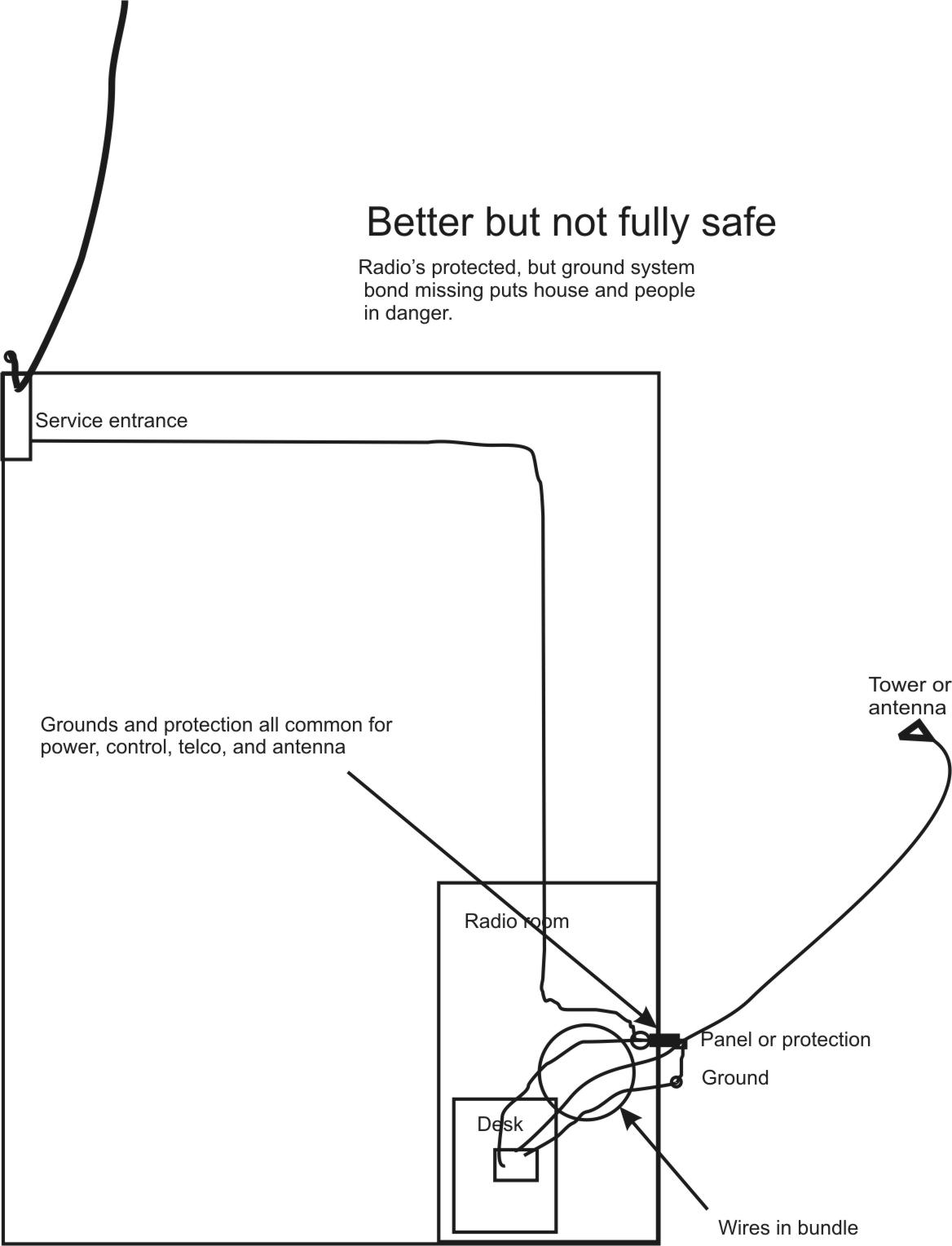
This is another system that significantly improves protection of the equipment at the operating desk. Unfortunately it omits the critical ground bonding necessary for full house protection. It does NOT meet national code requirements. The mains ground is not bonded to the station entrance ground.
EVERYTHING on the desk or connected to the operating desk in the radio room has to routed from the room common point entrance to the desk. No exceptions!
The three lines from the panel to the desk are all of the power lines, a line representing all of the control lines and antenna cables, and the ground wire.
These lines can and should be bundled or closely spaced if possible.
The problem? While it forms a protection zone in the radio room, the path for common mode lightning currents between the antennas and the power lines is through house wiring! This can cause a large voltage difference between electrical wires and other metallic conductors throughout the house.
Best by Far
This system meets all codes. This system is nearly as good as bringing all antenna system cables and wiring in at the house utility entrance (which would be perfect).
EVERYTHING on the desk or connected to the operating desk in the radio room has to run from the room common point entrance. No exceptions!
The closer the radio room cable entrance is to the power mains entrance, the more effective this system is.
The two lines from the radio room entrance ground panel to the desk include all power lines, with the medium size solid line representing a bundle of all control wires, all antenna cables and any desk grounding wire. These lines should be bundled or closely spaced.
Everything entering the desk area, including Telco and power connections, must be routed from the radio room entrance panel common point.
The value of the optional tower-to-station bonding conductor connection (longer dashed line) depends on distances. If the tower or antenna is near the house, it is better to bond it in. If the tower if more than 50 feet away, it might as well be isolated on its own ground because the impedance will likely be too high to be an effective bond.
The system to the left is my basic system. Pictures are shown below.
In the old days, desktop radio equipment needed a ground. This is because we did not have three wire plugs with safety grounds, and because gear used high voltages. Without a three-wire cord safety ground, there was a risk of 120 volts appearing on the chassis from power line wiring and component shorts. Even worse, a short between a power transformer primary and secondary could put thousands of volts on the equipment case!
Sometime around the 1960's, equipment and wiring started changing. Outlets added a third round pin. That pin connected back to the breaker panel case, and electrical system ground. Equipment started using a three wire cord with a permanent chassis ground, or was double insulated. Control wires also changed from 120 VAC (run directly from power mains) to low voltage 12-24 volt control wires. These changes worked to eliminate the need for a desk ground on modern equipment.
A second issue is RF desk grounding. In early days, we didn't have resources to explain balance and common mode RF currents. Long wire and Windom antennas were more common. While we still have equipment improperly manufactured, largely because of design errors in the book Baluns and UnUn's or lack of good cabinet integrity, most problems have gone away. For the most part, unless we have something wrong, there is no need for a desk RF ground.
Four common manufacturing defects causing RFI and making a desk hot with RF are:
Another misconception or myth is that filters divert harmonics and unwanted RF to ground. Filters on coaxial lines do NOT need to be grounded to block harmonics. Filters on power lines or balanced lines should be grounded to the equipment chassis, but not to earth ground.
One thing is very important. ALL equipment on the desk should be operated with the same cabinet potential. We want the RF transmitting shield connections between desktop gear to be as low as possible. This means we NEVER want RF isolators on desktop transmitting RF cables. It is good salesmanship or product marketing to tell people to install transmitting cable line isolators on the desk, but it is terrible scientific advice.
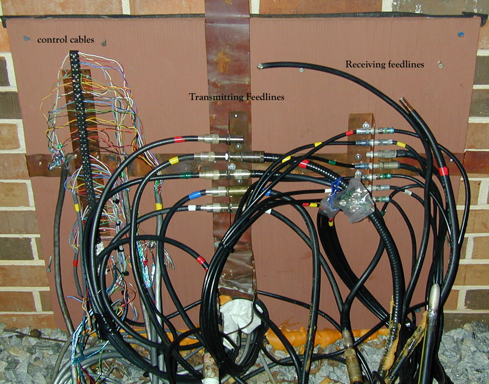
This is my house station entrance.
All control cables are shielded.
All shields are grounded.
The house is surrounded by a halo ground.
All desk power is grounded to station ground buss.
This is my "wire hider" built to look like a window seat. A finished cover fits over it.
All cables feed out from here in a bundle to the desk.
Just outside the rear wall is my outside grounding point. All cables enter through a 4 inch corrugated pipe.
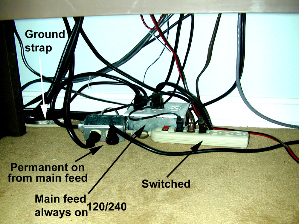
Under desk. All equipment on desk feeds from common outlets, and all wiring is parallel and close.
Without my "wire hider" I would have many dozens of cables feeding the desk instead of only several cables. The wire hider was the single best thing I ever did to clean up my desk wiring.
The only grounds running up to desk gear go to my old "unsafe" boatanchor gear.
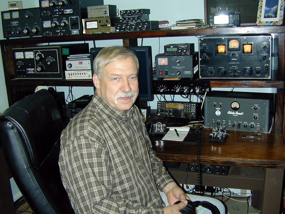
Picture January 2010.
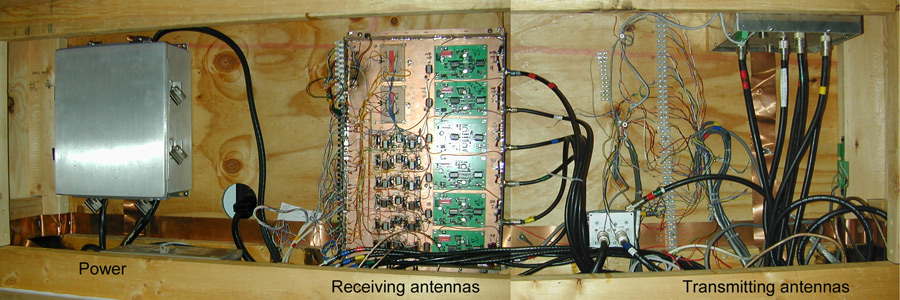
All this equipment runs from only several cables entering the desk area. With just a few cables I have the selection of almost 30 receive antennas, dozens of transmitting antennas, and five amplifiers (1500 watts from one sixty through six meters).
In addition the flip of a few switches and moving two or three multi-conductor plugs to new sockets transfers all antennas to my contesting barn.
Not only does lightning protection improve, station wiring is much more manageable.
The Globe Scout was the first commercial transmitter I ever owned. It was bought used from WRL and arrived via Railway Express at Central Union Terminal in Toledo, Ohio. It was a gift for passing my General. Prior to that all of my gear was home brew, including my receivers. See my boatanchor page