Crossfire Phasing
|
Crossfire Phasing |
|
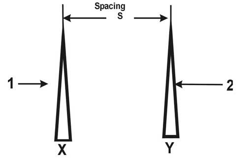
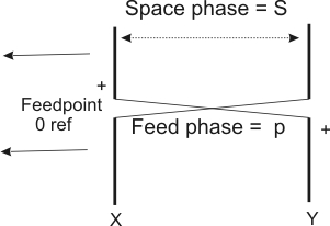
Most of our phased amateur antenna arrays are copies of systems or ideas used to build single frequency systems, like AM BC stations. Most of my work has been in HF systems in and around amateur bands. There is a significant conceptual difference between single band or single frequency systems, like AM broadcast, and systems that must operate over multiple bands or wide frequency ranges. A single-band single-frequency system is rarely engineered or planned for directional pattern behavior outside the operating frequency bandwidth. Traditional Phasing (In the text below, S will represent spacing and D will represent transmission line delays. Both will be expressed in electrical degrees.) Phased antennas elements, which includes Yagis (parasitically coupled), log periodic, driven element phased arrays, and most other multiple element antennas use radiated fields from multiple elements to produce nulls. The nulls squeeze the pattern in, forcing applied power to move into areas with less deep nulls. In other words, pattern formation and gain isn't so much that radiated fields add and sum, pattern formation and gain is primarily caused by radiated fields subtracting or cancelling. Because applied power is constant, adding nulls is like squeezing a balloon with a fixed volume of air. If we squeeze a balloon in at one area, the air moves out in another area. There can be some resistance to this, and we could do it by stretching an area out (additive phase), but the most space-effective method is squeezing the pattern tighter through nulls. Traditional phasing uses a phasing system that delays or advances phase to satisfy a 180 - s phase. Consider this two tower array with phasing for a cardioid pattern:
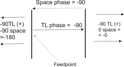
A traditional AM broadcast tower would plan a null based on phase delay = 180 - S. If S is 90 degrees (1/4 wavelength) phase delay would be 90 degrees. This would place the deepest null along the ground at the element with leading phase. The phase would look like this:
Radiation from element X (the 0 phase reference) to element Y is -90 in space and -90 in the feed system for difference of 0 degrees. They are perfectly in phase at any distance in line with the elements any distance past Y in the direction of Y. Radiation from element Y to element X (the 0 reference) starts at -90 at Y from the feed system plus -90 in space for a total of -180 degrees in the direction of X any distance past X. We have this pattern:
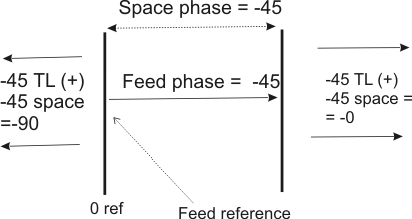
At half the frequency, using transmission line phasing, we have this:
We see now, at half frequency, we have -90 degree (phase quadrature) toward the reference element and in-phase to the right. This is about 3 dB F/B if current ratios are perfect. Here is a plot at half frequency with equal currents in each element (ideal currents):
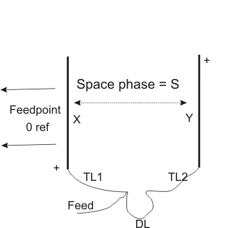
Crossfire Phasing There is a trick to phasing that I call "cross-fire phasing". I got this name from Channel Master and the "color crossfire" antenna, which was actually a two-band log periodic array. The Channel Master covered the lower VHF TV channels below the FM band, and the upper VHF TV channels above the commercial two-way and two meter bands. I like the name cross-fire as a description of a phasing system that progressively transposes element phase 180 degrees. This trick causes the phasing to behave like it is time delayed, rather than phase delayed. It removes the phasing errors we saw above when frequency is changed. The proper way to apply cross-fire phasing is to set delay approximately in step with the element spacing, but to invert phase by flipping the feed line at each progressive element. Here's how it works:
We have two elements with spacing S between X and Y. In this case the feed line has a velocity factor of nearly 1, being pure air dielectric: For phase and delays we have:
Green is forward direction field phase, yellow is reverse direction field phase. Note the reverse field phase combination is always 180 degrees out-of-phase. Why do amateurs, who almost always move around in frequency, use single-frequency 180-s ( where s is the element spacing in degrees) phasing systems? Probably for the same reason we use 90 and 180-degree shift in a four square. We started out wrong and just kept doing the same thing. While this won't provide octaves of bandwidth on transmitting, it does reduce phase errors across a single band substantially. It also provides a phasing method that allows us to build receiving arrays covering octaves without any loss of null direction or depth! All we have to do is keep element currents equal (in a two-element array). This is the principle that allows log periodics, EWE's, flags, pennants, K9AY, and other wideband arrays to maintain basic directional pattern over a wide frequency range. Other Antennas Verticals, loops, and other antennas can be fed with crossfire phase. While a direct transmission line feed, such as a log periodic uses, has to be open wire with a velocity factor near unity, coaxial and twin lead lines can be used with special care to feed systems. My 160 meter 4 square antenna, that works in eight directions, uses a form of crossfire phase. In the 1970's, I constructed a long loop array that used eight loop antennas in crossfire phase. Some antennas have built in crossfire phase, and we don't even realize it. The K9AY, the EWE, the flag, the pennant, and many other directional small loops use an integral form of crossfire phasing.
|