Enhanced F/B Beverages
Two Beverages are paralleled a short distance apart, and stepped one in front of the other, can be phased to remove unwanted rearward response. This really just amounts to end-fire phasing two antennas. It is effective with long antennas, and also increases F/B ratio (and directivity) with very short beverages (even those approaching 1/2 wl).
Many or most previously published systems use frequency-selective phasing systems. With such systems, operation on more than one band requires switching systems and many components. "Conventional thinking" will make the system more complex than needed, and actually provide less performance! This is unfortunate, because it is possible to design a simple phasing system with almost no components that will cover octaves of bandwidth...no switching required!!
The two basic schemes I've used are very simple. One system is totally independent of grounds at either antenna end, the other system requires grounds but is more forgiving of dimensional errors in construction. I've described a model of a loaded Beverage, for those who would like to experiment with a small-space Beverage at Slinky and Loaded Beverages.
Bandwidth of Directivity
In high-efficiency unidirectional transmitting phased arrays, element impedances change significantly with frequency and phase angle changes. In unidirectional high-efficiency transmitting arrays, mutual coupling causes each element in every end-fire element group to have greatly different feedpoint impedances. This seriously complicates the design of proper phasing and current distribution as frequency is varied. It is very difficult to cover a few percent of the operating frequency, let alone multiple bands, with a high efficiency array.
Most amateur receiving antennas copy what we do with transmitting, and many of our transmitting systems copy narrow-band single-frequency systems. This is very unfortunate!
The key to broadband performance is having frequency-independent stable element impedances, and similar element impedances, throughout the system. This requires thinking "outside the box", not copying of transmitting phasing systems (often TX systems that are not that well-thought-out or planned).
Requirements for Broadband Directivity
There are three ways to obtain stable predictable impedances or broadband directive performance:
- Multiple elements can be used, such as those in log periodic or Fishbone arrays
- Active elements that are far from resonance can be used (short non-resonant verticals or small non-resonant loops with amplifiers)
- Very lossy elements (even large elements) can be used, with losses swamping out mutual coupling effects
While all three methods work, the simplest systems generally use lossy elements that are large enough to provide sufficient external signal levels to overcome receiver system hardware noise.
Broadband phasing systems are easily implemented in systems where feedpoint impedance is stabilized through intentional or "natural" loss mechanisms. Losses are made large enough to "swamp-out" or dilute mutual coupling and resonance effects, antenna feedpoint impedance remains stable and predictable even when elements are end-fire phased with a unidirectional pattern and close spacing!
Beverages As Elements
In the case of Beverages, radiation resistance is very low (in the order of an ohm or two). Most of the resistance we see at the feedpoint of a Beverage is from dissipative losses in soil below the antenna, not from losses associated with radiation! In addition, termination resistance adds another source of loss (perhaps 30% of overall system loss). Overall, loss resistance in a Beverage is very high (several hundred ohms). This means the Beverage's feedpoint impedance is stable, even if mutual coupling radically changes radiation related impedances.
Note: Mutual coupling still remains, since mutual coupling is a function of element spacing and position. Even though mutual coupling still exists, it only affects the radiation resistance portion of element impedance. Since the large loss resistance (mostly from ground losses below the antenna) dilutes or swamps out mutual coupling effects, mutual impedances can be ignored.
Not only is a Beverage antenna's feedpoint impedance "immune" to mutual coupling effects when phased or placed near another Beverage, terminated Beverages offer a relatively constant feedpoint impedance over very wide frequency excursions. This makes arrays of Beverages ideal candidates for wide-bandwidth phasing systems, eliminating complex phasing and/or switching systems.
Types Of Phasing Systems
In order to better understand my antenna phasing systems, it is necessary to understand antenna phasing systems.
W8JI Parallelogram Array
Although it looks like a large horizontal loop, this antenna actually is two ground-connection-independent end-fire staggered (or stepped) Beverages. The short end wires form two single-wire feed lines at each end. One end-wire is series terminated with exactly twice the resistance of a normal Beverage, while the short wire at the opposite end is the feedpoint.
Stagger and spacing determines feed and termination location, the offset at the two ends being mirror images. A top view, looking down from straight above the antenna, looks like this:
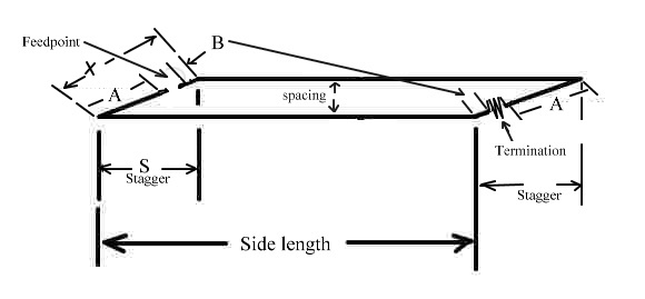
This is an exactly "top down" view, looking down at the antenna from right above the antenna!
Click here for an Eznec file.
Notice the feedpoint is offset towards the termination end (front) of the antenna, and away from the null direction. This is typical for crossfire phased arrays. Crossfire arrays respond away from the delay line direction, exactly opposite conventional arrays. The termination is offset the same amount, but moves towards the feedpoint end of the antenna.
The feedpoint terminals, being floated (push-pull), provide 180-degree phasing between the two elements. The extra line length to the forward (left and front) element provides the "Stagger" delay.
Consider the actual wire length of a "short side" called "X" (which is the same as A+B). This length is the same on both ends of the antenna. The difference between A and B must equal or be slightly less than stagger (S).
To determine the offset of feedpoint and load:
- Measure length of the end-wire, length "X".
- Measure stagger in the end-fire direction, "S"
- (X-S)/2=B
- A=X-B
You may want to slightly offset the feed by making B longer and A shorter. This will move the null upwards, forming a cone. It is best to model the results.
Let's review a system, assuming S is 60ft and X is 100ft. We have X-S=40 divided by 2 for 20.
B is 20, A is then 80. The difference is 60, and that is the phase delay. Assuming 1.5 ft per degree that is 60/1.5 = 40 degrees delay. S is 60/1.5, or 40 degrees also.
We have a 180 shift at the push-pull feedpoint, so -40 rotates to +140. We have a 140 lead in the forward element, with a 40 degree spatial array delay. In the forward direction (towards termination) phase is (-40) + 140= 100 degrees out-of-phase. This results in nearly the voltage of one element alone, when the two element outputs of the long sides are summed. Towards the null (feedpoint) phase is +40 + 140 = 180 for a sin180=0 or zero voltage, a perfect 180 null.
On the second harmonic forward array feed system phase is -80 rotated to +100. Spatial array phase is now 80 degrees, or -80 towards termination. The result is (-80)+ 100= +20 in the forward direction. The result is nearly twice the voltage of one element in the forward direction. In the reverse direction, array phase is +80 + 100 or 180 degrees out-of-phase. We once again have zero back-fire response!
The general pattern holds true for any length of S less than 180 degrees, although grating lobes would make the pattern useless. The array, with 60ft stagger S, is usable from about 5 MHz down to VLF.
Summary, W8JI Parallelogram Array
Placing the feedpoint and termination centered on the end-wires is like using 180-degree phasing.
Placing the feedpoint and termination at the stagger minus side length distance is like using S-180 degrees phasing on any frequency with one exception, the antenna fires towards the feedpoint offset. This always results in a perfect backfire null, regardless of frequency.
Here is a wire table for a short 160-meter W8JI Parallelogram Array:
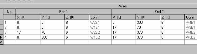
In a 370-foot length, this antenna has the following 20-degree wave angle pattern:
Average gain is -25dB, making the RDF about 6dB. In comparison a typical Beverage 370 feet long has this pattern:
If you wish to remove signals from the rear, the W8JI Parallelogram Array is a good broadband solution. It not only requires one transformer, one termination, and no ground systems at either end....it also is useful on several bands without switching anything!
Remember the above example is a reasonably short antenna, performance improves as side-length increases. There is no reason why this antenna can't be used from a band where it is only 1/2-wl long to bands where it is several wavelengths long, as long as you properly choose stagger and width.
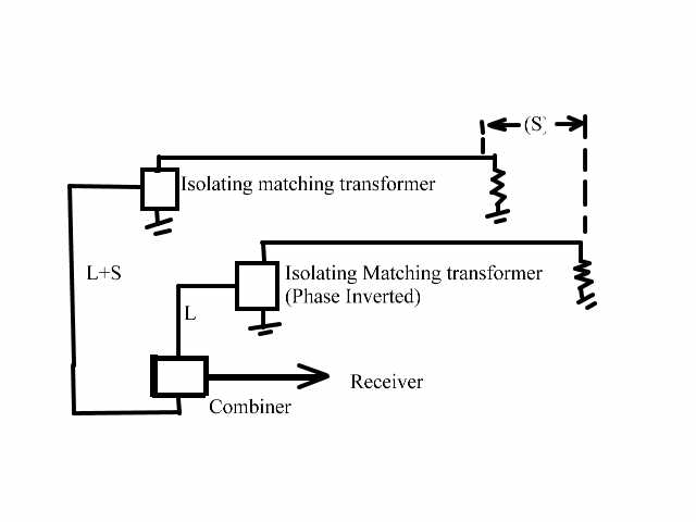
Crossfire-Echelon Beverage
This antenna is another frequency-independent antenna. It requires no band switching to work multiple bands. Because it uses cross fire phasing, rather than conventional phasing or hybrids, one phasing and delay line system covers several octaves of bandwidth.
A second feed method involves installing a pair of typical Beverages using isolation-type matching transformers, and inverting the phase of one antenna. Instead of being fed through two equal lengths of transmission line with a conventional splitter or combiner, the rearward stepped antenna (null direction) has an additional electrical delay equal-to or slightly-less-than the system's stagger distance in degrees. The delay line calculation can be done at any frequency, since stagger and delay change in step with frequency!
Performance is nearly identical to the above array, even very short antenna lengths (down to 1/2 wavelength) provide good F/B ratio. Of course the antenna will work better if length is increased. This arrangement is slightly more forgiving of dimensional errors than other systems, because each antenna is independent.
Remember you need a 180-degree flip at one feedpoint!! When you do this, the electrical delay of the antenna located towards the NULL must be S or slightly LESS than S. Using slightly less than S elevates the null and forms a cone, improving null usefulness and RDF of the array.
It is important to makes sure antenna feedpoint impedance is correctly matched to the transmission line. Be sure to measure SWR with an antenna analyzer!
You can also use a balanced wire feed, here is an EZnec model of an array using a combination W8JI parallelogram and Echelon-Crossfire feed.