Loading Inductors
|
Loading Inductors |
Optimizing InductorsWhile intended mainly for antenna loading coils the text below also applies to other resonant systems, such as amplifier tank circuits. Before doing anything with information in this article or any other article related to loss and efficiency in antennas, please read the radiation resistance article on this site! Related pages:Optimum form (length to diameter and turns spacing) of any inductor depends heavily on the end-use of the inductor. Current through and voltage across an inductor, as well as the operating reactance, determine optimum physical attributes. Current and operating frequency mainly determines minimum conductor size, although turn-to-turn spacing, spacing to surrounding objects, and thermal characteristics also affect minimum conductor size. Voltage across the inductor, as well as voltage from the inductor to surrounding objects, establishes minimum conductor spacing and insulation requirements. Environmental conditions determine some aspects of construction, including turns spacing, insulation, form type, and requirements for weatherproofing. Operating reactance influences both material choice and optimum physical form of the inductor. Making the matter more complex, a seemingly simple change inside an inductor often interacts in very esoteric ways. For example, if we add insulation to weatherproof an inductor, the insulation will reduce high frequency Q. Part of the Q reduction is from dielectric losses, and part of the Q reduction is from increasing stray capacitance across the inductor and stray capacitance to the outside world. The question is always if the change will be noticeable; the answer is "it depends on the reactance and the system the inductor is used in". Some things are very counterintuitive. For example, we assume narrow bandwidth is a sign of low loss (high efficiency). Yet adding unwanted shunt capacitance across an inductor, counter intuitively, can decrease system bandwidth while increasing loss! If we measure Q externally by looking at a plot of 3 dB voltage points as frequency is varied, increased shunt capacitance or turn-to-turn capacitance will actually decrease system bandwidth while simultaneously increasing losses in the inductor. We cannot always rely on bandwidth as a measure of efficiency. High Impedance SystemsIn higher impedance systems, optimum form factor (length -to-diameter) leans towards a longer inductor with a smaller diameter. This is because a longer inductor with smaller diameter has less stray capacitance from end-to-end. A smaller diameter and shorter coil can have less stray capacitance to the outside world, since current isn't shunted out of the coil through displacement currents. Even the best insulation materials have a deleterious effect on component Q when impedances are high. This is because insulating materials increase stray capacitance. Dielectric constant can become more important than dissipation factor in choosing insulating materials, but the ideal dielectric would have the lowest dissipation factor and lowest dielectric constant. There is no clear boundary between high and low impedance systems, but generally high impedance systems would include electrically short mobile antennas, or any other system, where more than one thousand ohms or so of inductor reactance is required.
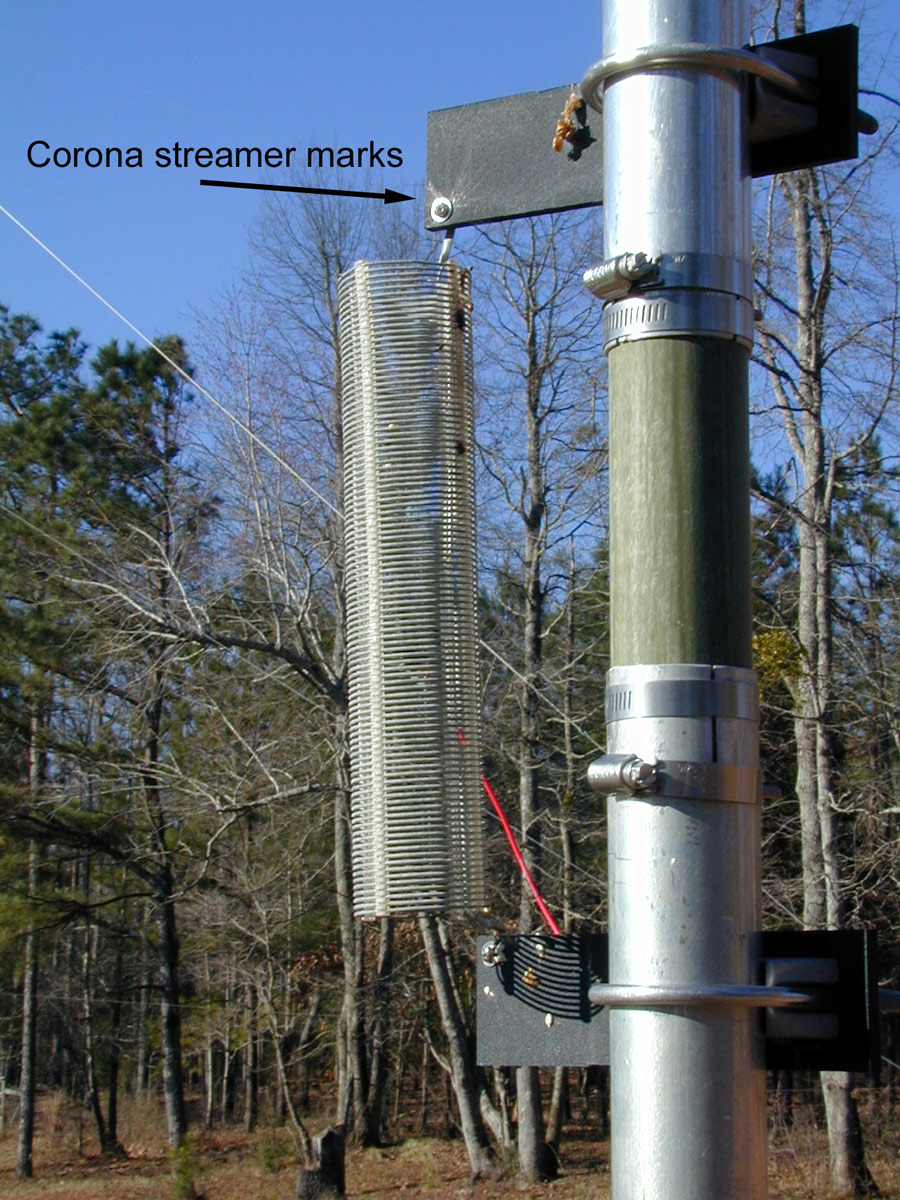
This loading coil is a good example of why high-reactance loading inductors should be longer and narrower than inductors used in low-impedance systems. This loading inductor is near the bottom of a 43-foot tall vertical. The top of the coil directly bonds to the upper vertical section with a jumper wire (hidden) on the far side of the plastic insulator. Shiny streamer marks on the surface of the plastic show where the intense electric field has caused corona or "streamers". This vertical was operated at a kilowatt. Voltage was so high the edge of the metal washer produced corona streamers that etched the plastic! Even when the black plastic was replaced with Teflon, the corona ate into the Teflon! The long form factor, about 6:1 (length six times diameter), minimizes capacitance and maximizes voltage rating from end-to-end of the loading coil. It prevents arcing across areas of the coil, and makes the inductor less sensitive to moisture changes.
Low Impedance SystemsWith low impedances, optimum form factors become more "square". "Square" meaning the length to diameter ratio is unity. Optimum length in low impedance applications is short when compared to diameter because stray C has very little effect. The load capacitance or resistance from the external circuit dominates the system current when the impedance of the inductor is low at the operating frequency. Insulation has very little effect because any change in stray capacitance, even if a large percentage of the air dielectric capacitance of the coil, is very small compared to the fixed external capacitance. Two cases where an inductor might be a low impedance are antenna traps and traditional amplifier tank coils. In these cases intentional external low reactance capacitances often shunt the inductor, and the inductive reactance is often hundreds of ohms or less. The internal winding turn-to-turn capacitance, and the stray capacitance of the inductor to the outside world, is small compared to the desired or necessary external capacitances.
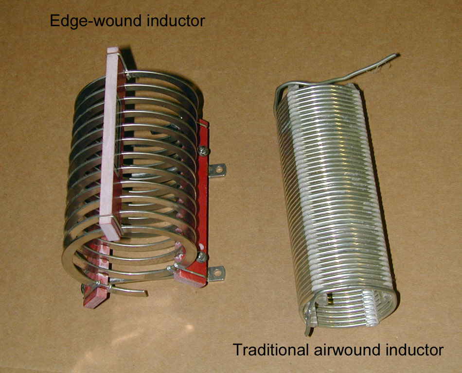
The edge wound inductor on the left is mostly suitable for tank circuits or systems where there is considerable external capacitance involved, or where the required inductive reactance is low. This edge wound inductor has a form factor of 1.3 : 1 (length to diameter). As more reactance is required, the coil's optimum form factor progressively increases. The air wound inductor on the right has a form factor slightly over 2 : 1. Optimum turns spacing is about one wire diameter. Although neither of these inductors meet that criteria, they both avoid any insulation or dielectric in the gap between turns or insulation covering or coating the conductor.
Insulation, even the best insulation, will decrease inductor Q. This does not mean we should never insulate a coil, that Q reduction is always measureable or noticeable, or that insulated coils are "bad". Even where insulation reduces Q a measureable amount, we sometimes must compromise Q for reliability, life, weather immunity, and/or cost. Insulation is sometimes necessary to prevent short circuits or arcing, although it is a good idea to avoid insulating conductors or the area around conductors when reasonably possible. How can we tell if the coil design is critical?The transition between critical and non-critical systems is somewhat wide and difficult to define. Design is a complicated blur of many factors. For example, working hard to push inductor equivalent series resistance (ESR) very low when the effective series resistance of the inductor is low, compared to the loss resistances of the system outside the inductor, doesn't make sense. The same is true for power losses. If the system outside the inductor is very lossy, loss in the inductor becomes much less important. One example might be an inductor loaded Marconi antenna with very poor ground system. If we apply 400 watts of transmitter power and ground system losses are 200 watts, doubling inductor Q might only change system efficiency a fraction of a decibel. Other than temperature rise in the inductor, who cares if a system with 200-watts of ground loss wastes an additional 2 watts or an additional 4 watts in the inductor? This is why very large mobile antenna loading coils generally offer marginal improvement over smaller inductors. One way to roughly determine the quality of an inductor without fancy test equipment is to compare out-of-circuit self-resonant frequency (SRF) of an open inductor (do not short the ends together) to the expected operating frequency. A good inductor will be self-resonant a minimum of four or more times the operating frequency. A simple Grid Dip Oscillator is all that is needed, but be sure you use a real GDO. Antenna analyzers make very poor GDO's! The best general idea is to make an air-core inductor as close to a 1:1 form factor as possible, while keeping the SRF as far above the operating frequency as possible. It is possible to test an inductor or compare power loss between different inductors by enclosing the inductor in a Styrofoam box and measuring temperature rise with a known applied current, although the ability to measure loss resistance and reactance at the operating frequency is certainly much faster. Overall Design CompromisesWeight, size, and cost often require use of less-than-ideal materials and construction, but careful design generally results in a compromise that won't noticeably affect system performance. As a further complication, very simple systems might work quite differently than we intuitively believe. Many experimenters fail to consider what the inductor does in the system, and how the inductor behaves internally. For example many people assume, with a fixed amount of applied power, as voltage increases at different points along a coil current in the coil must be must proportionally decreasing. The logic or intuition is based on the fact power is I times E. That doesn't apply to reactive systems because there can be power factor involved. Voltage and current are not exactly in-phase or 180-degrees out-of-phase, so the simple product of E*I will not equal the applied power. Because of the phase difference, we would have consider the phase relationship. ErrorsI've noticed programs and formulas often over-estimate maximum obtainable inductor Q. I'm not sure why this occurs, but it seems to be somewhat common. Sometimes the estimated Q is well beyond any real world Q that is obtainable. I've also seen Q measurements made far below the actual operating frequency, or made with inadequate methods or marginal equipment. This is especially common in high impedance high frequency systems. Worse of all, antenna manufacturers and antenna builders tend to under-state or under-estimate loss in other forms of loading, specifically linear-loading. Because of the very poor form factor, most linear loaded systems have Q's in the double digits. While linear loading provides wide bandwidth, it also adds needless resistive losses. It is not "lossless linear loading", as some have claimed. I've found it difficult here to get perfectly repeatable measurements even using expensive laboratory equipment. For example I use a HP-4191A Impedance Analyzer. I still cross check inductors by placing them in a large copper-lined box and tune them to resonance with vacuum variables (Q>50,000). By measuring inductor current and voltage across the vacuum variable, or measuring the series or parallel RF resistance, I can determine Q or ESR. The highest Q I have found is around 1000 or just over 1000 when determining Q by using X / ESR = Q . There are five common errors we should avoid:
Range of Inductor Form FactorThere are two critical form factor dimensions, diameter and length. The ratio of diameter to length has two limits. The first limit occurs when the inductor occupies only one wire diameter as the length. The other limit occurs when the inductor is one wire diameter in diameter. The first condition would be met by a single layer pancake coil, the second by a linear conductor such as the inductance of a single wire transmission line. Optimum form factor occurs between these two extremes, and varies with the exact application. Length-to-diameter ratio is important for two reasons:
These two situations are obviously in direct conflict, a balance must be achieved. Optimum balance between conflicting L/D effects listed above depend heavily on external circuit capacitance and operating frequency. There is actually only one nearly constant parameter in design of high-Q RF solenoid inductors, turn-to-turn spacing. Optimum turn-to-turn spacing occurs when the spacing or gap between turns is about the same diameter as the wire. If the turn-to-turn gap is filled (even partially) with insulation, optimum conductor spacing increases. For the purposes of this article, the following terms are used:
As a general rule, Q in a RF inductor peaks with a form factor (L/D) between 1 and 4. The size and shape of the conductor used in the coil sets the optimum diameter, larger conductors require larger diameters. Lower optimum L/D ratios (near unity) appear in systems where higher amounts of external capacitance load the system. Two examples would be amplifier tank circuits or large antennas with considerable loading capacitance beyond the coil. Another way to view this is by resonant frequencies. Form factor moves closer to 1:1 when an inductor is operated far below its natural self-resonant frequency. Higher optimum L/D ratios (up to 4:1 or more) occur when capacitance values external to the coil are reduced. Small mobile antennas without hats, especially top-loaded antennas, require longer form factors. Such systems operate the inductor closer to its self (parallel) resonant frequency. The Reason Optimum Form Factors VaryAs mentioned earlier, the underlying reason for change in optimum form factor in systems with different external circuit impedances rests almost entirely in the inductor stray capacitance and the mutual coupling between turns. With high external capacitance, any reasonable amount of internal stray capacitance shunting the inductor only causes a very small change in circulating current in the inductor. The low-impedance external circuit can almost exclusively determine current in the inductor. In this case, inductor Q is set mostly by conductor resistance in the inductor, so anything we do to minimize the copper path resistance will help. This would include closely packed turns that increase mutual coupling between turns. In a low impedance system designers can place turns closer together, increasing mutual coupling or flux linkage from turn-to-turn. Since external capacitance generally is large, any increase in inductor distributed capacitance will have very little effect on the system. The most important goal is to reduce wire resistance by minimizing wire length. Dielectrics around the conductors have little effect on Q, because increases in capacitance caused by replacing air with a dielectric has little effect on the overall circulating currents. The type of form (solid core or air) and materials used in the form or insulation on the wire are far from critical because the electric field around the coil is very small. For example I measured a number 8 gauge 13.5 uH air-core inductor with a diameter of 1 inch and length of 3.5 inches on 4 MHz. It had: 339 ohms reactance 2.26 ohms resistance 150 Q Adding a tight fitting solid Delrin core, Q dropped to 145. Changing the Delrin to Teflon produced an identical Q of 145. All three Q's are within measurement error of the Agilent Network Analyzer used. We should consider them all equal. As the system's external capacitance is reduced, circulating currents inside an inductor become increasingly influenced by stray capacitance. This includes capacitance within the inductor as well as capacitance between the inductor and objects surrounding the inductor. When external capacitance is reduced, the coil ends must be increasingly separated from each other. The form factor chosen must reduce coil diameter while increasing length. In high impedance (reactance) systems, reducing capacitance improves component Q in spite of the resistance penalty resulting from increased conductor length required in long form factors. We also must avoid using dielectrics near or in the inductor, especially any dielectric coating or between turns. Dielectrics other than air or vacuum, even low dissipation factor dielectrics, increase stray capacitance. Anything that increases capacitance will reduce component Q, and ALL dielectrics (other than air or vacuum) increase capacitance. The most noticeable effects in high reactance systems often come from dielectrics increasing capacitance, rather than actual dielectric losses! The increase in loss can be directly proportional to the increase in capacitance, even when required turns are reduced. Low-loss Teflon or Polyethylene dielectrics can be nearly as detrimental as higher dissipation factor materials like fiberglass or Delrin. In very high impedance systems, such as a physically large loading inductor with a very small "stinger" just above the inductor, current can actually vary significantly along the length of an inductor. This is because displacement currents can flow out of the coil through the stray capacitance to the outside world. In properly designed or well thought-out systems, this will not occur to any significant extent. If it does occur, it might be time to re-examine the basic design. This again has the effect of reducing bandwidth while increasing losses. Inductor Modeling ProgramsMany inductor modeling programs fail to consider two important effects:
The first effect causes Q to peak well below the self-resonant frequency of the inductor. The second effect causes a decrease in Q as frequency is increased or as turns are brought closer together. The second effect occurs because current flows in a smaller and smaller cross section of conductor with increasing frequency. If a model, prediction, or estimate does not show Q dropping drastically as first order (parallel) self-resonance is approached, the results almost certainly contain significant Q errors. I've corresponded with some program writers who claim to have verifying measurements, and found their test equipment doesn't reliably operate (or operate at all) at the operating frequency of the inductors! Verifying inductor Q at frequencies far below the operating frequency in the model does NOT provide any assurance the model or predictions are correct. We have to measure at the operating frequency. Optimum QThere is a strong tendency to overkill the size of inductors, in an effort to reach unrealistic Q factors. Examples are commonly found in high-performance mobile antenna systems, where ground loss and other system resistances dominate the system. We often find high performance inductors with Q's in the several hundreds (at the upper practical limit of Q) and very low ESR's used in systems where overall loss resistances normalized to the feedpoint are very high. Even though electrical problems are NOT created when using the highest possible Q, there is a point where the end improvement in signal level does not justify the physical size and cost to obtain "excessive" Q. One example can be found in my Trap Measurements article, where differences in trap Rp (parallel resistance) when #10 AWG and copper tubing are compared, with unnoticeable changes in performance. Another example appears in my mobile and loaded antennas article. Inductor Placement in AntennasThe optimum location of an inductor varies with ground resistance and overall length of the antenna. Fortunately efficiency changes are smooth and gradual changes. Minor errors in placement generally do not result in noticeable efficiency changes. Radiation Resistance and Mobile and Loaded Antennas articles on this site give some perspective of how load placement affects radiation resistance. Q RangesThe highest Q HF inductors I have measured, at least when operated away from self-resonance, are copper tubing coils and edge-wound inductors, such as those commonly used in high power tank coils. The highest Q I have measured in very large inductors of optimum form factor in the HF range has been near 1000. Miniductor-type coils have a surprising amount of Q for the wire size, and maintain Q better as self-resonance is approached than larger coils. These are the typical ranges of peak Q I have measured:
Final CommentsWe should keep the following in mind:
|