Antenna patterns are formed through nulling or removal of radiation from different directions, and sometimes by reinforcing of radiation in other areas. In other words, the pattern shape is sometimes caused by in-phase addition of radiation from two or more physically separated areas, by subtraction of radiation from two or more physically separated areas, or a combination of the two. Pattern shape can be engineered by planning radiation from different spatial areas arriving at various spatial points in predictable, controlled, phase relationships.
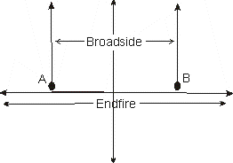
Antennas can be formed into arrays through use of elements or cells, each with a pattern. Those cells can be combined through a process called pattern multiplication, to form a larger cell or array of cells, increasing directivity or gain. The two basic combination methods are broadside and endfire, each having many subsets of categories or names. For example a collinear arrangement describes elements aligned in a single line end-to-end, but it actually forms a broadside radiator. A Yagi on the other hand is an end-fire system with elements excited via mutual coupling.
Looking at two small sources without regard to polarization or phase, they would be classified by the direction(s) of radiation compared to a line drawn through the elements (sources):

The farfield pattern is formed by the vector combination, or
addition, of radiation fields from two or more coherent radiation sources. This
is independent of the local induction or static energy storage fields.
The second (or higher order) EM source might be radiation from currents induced
in a "reflector" or "director" of some type, or it might be from another driven
element that shares power from a common point. The important thing to remember
is patterns are formed by vector addition of EM (radiation) fields from multiple
radiation sources, even if those sources are passive "reflections".
Near and Far Fields
Any system has a near-field area, where pattern has not fully formed. This area, depending on antenna size and characteristics, can be quite a distance from an antenna. Let's ignore the field impedance problem (ratio of electric to magnetic fields) and just look at electromagnetic radiation.
Physically close to antennas A and B, field strength levels change rapidly with small distance changes. This is because of wave spreading, which is related to field strength through the inverse square law. This law says if distance changes, field strength changes by the inverse of the distance change squared. If we double distance, field strength becomes 1/2^2 or 1/4 of initial value.
This can present a pattern problem close to elements when elements are phased. I run into this trying to cancel or null my 4-square signal out of my closer located Beverages. This type of problem occurs when the elements being phased are not insignificantly spaced compared to distance from the desired null point.
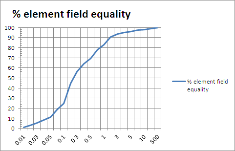
For example, my 160 four square has elements about 135 feet apart around the square, or 191 feet diagonal distance from end-to-end. The closest Beverage is only about 250 feet from the closest four-square element. The furthest 4 square element is 191+250=441 feet away, while the closest element is 250 feet away. One element is 1.76 times further away, so the furthest element (for equal applied power) would have just over 32% field energy at the Beverage's closest point. (Voltage and current are each reduced to about 60% of an element 191-feet closer.) The four square, no matter how well nulled at a distance, is not fully nulled in close because the reference point is too close to the four square compared to element spacings.
This is why, when using antenna patterns to null relatively close noise sources, a small-area array is often better. The inconsistency of pattern in close is also why reports of relative performance in real-world installations with significant local noise are meaningless as an overall rule in other installations.
If the antenna and noise are not in each other's Fraunhofer regions, patterns are not fully formed. Things may not work like we think. Unfortunately, on 160 meters, physically large antennas and arrays of antenna make it very difficult to be in the Fraunhofer region, or far field.
At some distant point, the signal arriving from A and B (above) will look like it has traveled the same distance and the same angle, no matter what the reference point. Let's say my Beverage was 1500 feet from my four square's closest element. In this case, the relative spacings are either 1500 feet to the closest element, or 1691 feet to the furthest element. Field energy at this greater distance is now within 22% and electric field strength within 12%.

For 0.1 wavelength spaced radiation sources (elements) distance to closest element.
You can actually verify this with an EZNEC model. EZNEC plots fields at a very large distance over flat ground. This does not actually represent the true patterns of antennas at groundwave distances, which means directivity as important to local noise is not accurately represented in patterns. While I warn that RDF (directivity for receiving or receiving directivity factor) is only accurate for uniformly distributed noises, EZNEC falsely nulls low angle and groundwave signals.
There are three ways to look at fields more accurately:
1.) Set ground conductivity to perfect. This only works when using vertical antennas, or antennas that do not depend on poor soil for operation
2.) Use the near field tab and set tabulated distances to desired distances
3.) Model an additional element with a load, set element length and load for agreement with electrical field strength in volts per meter (or some other reference)
Near Field Patterns