diversity receiver and transmission
|
diversity receiver and transmission |
|
Some Phase measurements of antennas Antenna DiversitySingle Antenna with Multiple Polarization for Diversity There are claims a quad antenna, by virtue of vertical side wires and horizontal top and bottom wires, provides polarization "diversity". This just isn't true at all! The quad is normally a single polarization antenna, although some very specialized feed systems can create a rotating (circular polarized) wave. If for example the feed system of the quad antenna was circularly polarized, feeding the sides and flats in phase-quadrature, the cubical quad would transmit and receive a rotating wave (circular polarization) of no particular polarization. A standard quad antenna, however, is just a single polarization antenna. Other antennas sometimes claimed to be non-fading by virtue of polarization diversity are not diversity either, and are certainly not "non-fading". An intentional mix of vertical and horizontal reception (or transmission) from one antenna, like a Windom antenna with a radiating vertical feed line, are generally linearly polarized antennas. Even two separate horizontal and vertical antennas, combined into one receiver or transmitter, are not normally polarization diversity. Such a mix of antennas are not non-fading, they offer no fade reduction. Polarization of antennas such as these are primarily a single polarization that is tilted at different angles in various directions. There can be a small portion of the radiated field that is rotating polarization with time (circular polarization), but is not helpful in reducing fading.
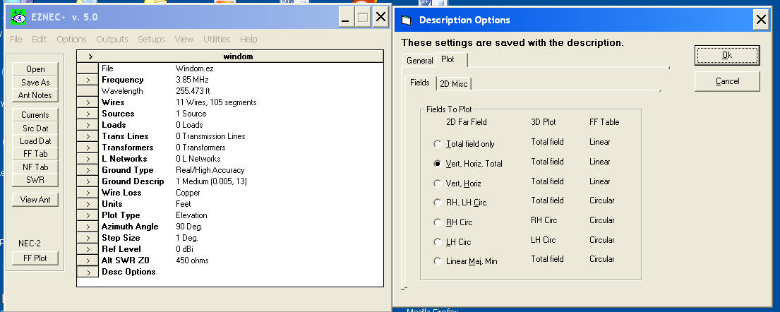
Because Eznec and other programs only plot two polarizations of patterns, perfectly vertical and perfectly horizontal, skewed or tilted patterns appear as a "mixture" of two polarizations. The radiated field is really a single uniform polarization that is tilted at an angle. This is the pattern at 90 degrees azimuth.
This is the same antenna at 135 degrees azimuth. Notice V and H are now approximately equal at some elevation points. This is because polarization is tilted at 45 degrees at those particular elevations and at this azimuth angle. If the display included phase, we could calculate the angle of the polarization tilt.
EZNEC does have a way to look at circular polarization content. Go to the Desc Options tab (at the bottom of the window list). When you open the "Description Options" window select one of the Circular "Fields to Plot". This will tell you the ratio of linear polarization to circular (rotating) polarization. Remember for skywave, circular polarization will generally at best not improve things...and more often make fading worse!
Summing or combining two different polarization antennas will not decrease fading on a skywave path. If we directly sum two sources, one vertical and one horizontal, the result is a single tilted polarization. The casual observer might think he has obtained isolated vertical and horizontal responses when he looks at a computer model, but the dual polarizations displayed are a necessary result of display limitations! Traditional modeling programs can only display polarization exclusively in V (vertical) and H (horizontal) without regard for phase. This means a tilted pattern of a single polarization displays as a mixture of V and H of differing levels. The antenna's radiation actually is a skew or tilt of a single polarization. If the pattern displayed had perfectly equal V and H fields at some directional angle and elevation on a plot or display, and if a receiving antenna was tilted 90 degrees from the maximum sensitivity, the result would be nearly zero response. Circular Polarization If we mix or combine a vertical with a dipole of equal field strength, and if we look at the true polarization from broadside to the dipole, we would see a single tilted wave of only one linear polarization. Any skywave signal would be just as likely to hit the null of that system as it would a pure vertical or a pure horizontal dipole. There is no reduction in fading, and fading can actually increase. This is because skywave normally has multiple paths of varying polarizations and phase delays, and these multiple signals are as likely to subtract as add at any given angle. Combining multiple polarizations, or multiple wide-spaced antennas, actually increases long term fading by increasing response to secondary paths. As a matter of fact, a perfectly horizontal dipole is only perfectly horizontally polarized directly broadside to the dipole. As we look at the dipole moving around towards the ends, the polarization tilts more and more vertical! There is a way to
have an infinite
number of
polarizations at
some angle and
direction, circular
polarization.
Circular
polarization is a
time-varying
polarization. At any
instant of time, we
have a single
polarization but the
polarization angle
actually rotates
over time. It passes
through vertical and
horizontal and
everything between,
rotating like a
spinning dipole. It
takes one millionth
of a second for a 1
MHz wave to rotate
360 degrees, because
the rotation time is
the reciprocal of
the operating
frequency. The lowest fading
transmitting antenna
(and receiving
antenna) actually is
one with a single
polarization
that is focused as
narrowly and cleanly
as possible at the
best wave angle and
compass heading, with the
fewest side lobes
that might respond
to unwanted
multipath. Circular
polarization
increases fading on
skywave paths, when
either receiving or
transmitting.
Diversity Receivers and Reception
True diversity
for skywave is just
as effective with
two same-polarization
antennas as with V and H antenna combinations. Using similar or same
polarizations, the
antennas must be spaced
a few wavelengths or further
apart. True
diversity always requires
some form of
intelligent summing
of the signals. To
be effective,
signals cannot just
be directly mixed
either at audio, IF,
or
radio frequencies.
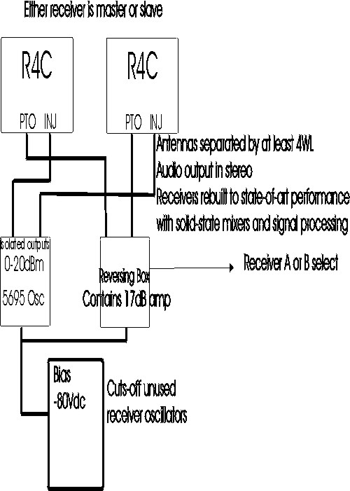
True vs. Stereo DiversityI use a loose form of diversity reception on 160, 80, and 40 meters I call "stereo diversity". This really isn't true diversity where the receivers vote and the best S/N ratio captures the audio output, it is a system that requires our "brains" manage signal summing and/or noise subtraction. I've found this technique good for substantial improvements in readability of noise-floor signals. The difference can be worth as much as a signal being nearly readability 5 (perfect) in stereo to readability 2 without. When signal-to-noise ratio is marginal, stereo diversity can be make all the difference in the world in readability. I implement stereo diversity by phase locking two separate receivers (heavily modified R4C's) together so audio outputs are exactly locked in phase. The receivers are virtually identical, even to the point where I hand select crystal filters for equal group delay change over the filter passband. Every oscillator in the receiver system is common to both receivers. I'm aware of only one commercially available amateur receiver that does true stereo diversity, the Elecraft K3. I currently use an Elecraft K3 since it is the only system that phase-locks two identical receivers, it interfaces a good transmitter with the receivers, and is a modern stable design with accurate frequency readout. The stereo method, used with the proper receivers, allows successful combining of two antennas or antenna arrays that are several wavelengths apart. Normally this would be impossible, since the phase of signals from two wide-spaced antennas continuously changes from one moment of time to the next. If we simply summed the signals in phase, in a matter of seconds or minutes the phase would rotate 180-degrees out and cancel. It is helpful to think of summing, even at audio, as system with both antennas directly combined into one very large array. There is actually no difference at all if we summed at RF before one receiver, or summed at audio after processing through two separate receivers! With the wide spacings useful for diversity, the resulting pattern would be very sharp. There would also be many deep nulls. With such a sharp pattern (from the wide spacing) that the desired signal would continually slip from a pattern peak to a deep pattern null. If antenna spacing is less than 1 wavelength and we directly sum the audio, the resulting pattern is just like phasing the antennas directly together! The only difference is we cannot control the phase very well unless both channels share common oscillators. This is not the same as using multiple VCO's with a common reference oscillator. The Elecraft K3 actually rotates phase as the VFO is tuned, so even if we (through some sort of luck) had a good pattern on one frequency the pattern would change as the VFO changed frequencies. I actually control the phase in my diversity R4C's by changing the phase in the 50 kHz BFO. Since the PTO and all other oscillators are common from the master receiver, the phase difference remains set by the BFO phase difference. The controlled predictable stable phase allows the R4C's to be used for direction finding as well as signal nulling when the audio channels are mixed into mono. By allowing our brains to process the signals, we can mentally extract coherent tones from random noise. Stereo reception using two very quiet wide-spaced antennas causes background noise to appear smoother and more "hollow sounding". The coherent signal appears to stand out from the noise, even as phase is rotating. Some of the recordings on my DX Sound Files page are in stereo. You can listen to this effect with stereo headphones by changing your computer's volume control settings to stereo or mono. Stereo Diversity As with many things, it's difficult to say who actually started stereo diversity. I had one of the earliest systems I'm aware of. After unsuccessfully attempting to build a voting system in the early 1970's, and after unsuccessfully attempting to directly combine various receiving antennas, I experimented with R4C's. I initially tried running one VFO to both receivers via the PTO jacks, by "tricking" one receiver into thinking it was feeding a T4XC PTO in transceive. Instead of feeding the PTO into a T4X transmitter, I fed it to a second R4C. This gave me one receiver as a master oscillator for both carrier the carrier oscillator, one tuning knob tuned both receivers. While each receiver sounded OK by itself in mono, in stereo this produced an odd sounding signal.
I discovered I also needed to use a common carrier oscillator. Once I shared the carrier oscillator, the receivers were phase locked. If I combined the audio outputs in mono, I could peak or null any tones by moving the passband tuning knobs. In stereo, with the identical R4C receivers, results were amazing. After some learning curve for my ears, I could copy signals that were buried in the noise in mono. After proper configuration, background noise took on a different hiss or "color". If I ran one common antenna into both receivers, it sounded just like one receiver. If I split antennas and used some loop arrays in one ear and the Beverages in another ear, the noise got a distinct hollow sound and signals stood out. Another interesting effect of combining channels using common oscillators is a signal can be peaked or nulled by varying phase shift between the two channels. This only works when common oscillators are used for each channel, and where a method of altering phase shift is available. In a similar manner, by watching phase error between independent channels fed from widely spaced antennas, direction of signal arrival can be determined. There has been some attempt to copy what I started years ago with two R4C receivers, stereo diversity. Despite what we are sometimes told, we can't simply adjust two unlocked or dissimilar receivers to the same basic frequency, pipe one output into each ear, and have effective diversity. This is especially true with unlocked receivers that are even a fraction of one hertz different in frequency. Our brains are unable to phase-lock or phase-compensate the signals unless the lock frequency is closer than a small fraction of a Hz, perhaps 1/25th Hz or less. The more rapid the phase rotation, the less effective the brain becomes when adding desired signals and subtracting noise. Phase rotation between receivers has to be significantly less than the natural atmospheric-caused phase rotation between the stereo antennas. There are articles describing how to electronically lock the receiver tuning of the FT1000D (and other receivers) so the sub-receiver tracks the main receiver. This does somewhat work in the FT1000, because the oscillators share a common time base. The main problem with the FT1000 is the second receiver isn't a very good receiver, the filters do not match, the AGC does not match, and phase shift through the receivers (especially as the signal moves off the filter center) is not at all similar. I had similar disappointment with the Orion system. To the best of my knowledge the K3 Elecraft is the only receiver that has absolutely identical receivers that share one common reference system. That is what I have switched to now. The K3, unfortunately, cannot be used to measure phase differences because the oscillators are not perfectly phase synced. It does work OK for diversity.
Testing For Diversity CapabilityYou can test your system for correct phase-lock by tuning in a carrier (like WWV) and mixing the two outputs together. When audio levels are equal, you should hear no warble or vibrato in the tone. You should hear something between a full null or peak in level, a steady tone that varies only in level. as the receivers are tuned across the signal. If your system fails this test, it will deduct greatly from possible stereo diversity advantages. Click here for a failed test. Click here for a passed test. Remember any warble or slow fade variation indicates the receiver is unacceptable.
Best diversity Receiving AntennasFor best performance, diversity antennas should be spaced more than 2 wavelengths apart. Both antennas should have similar directive patterns and similar signal-to-noise ratios. Polarization diversity generally only works on higher bands. It is not practical to have a low wave angle horizontally polarized antenna for 160 or 80 meters. Remember a Beverage antenna is vertically polarized, it is not horizontally polarized!
Diversity TransmittingOne common thought or advertising claim is by transmitting both vertical and horizontal via skywave, we have the best of two worlds. There is an idea or belief we can build antennas producing two independent polarizations, and the resulting "dual polarization" will provide the best of both worlds and reduce transmitted signal fading. Several obvious flaws with this concept are outlined below. Generating Two PolarizationsWhen speaking of polarization, we are talking about the direction of the imaginary flux lines in the electric field. When dealing with the far-field effect called EM radiation, the imaginary electric and magnetic flux lines are conveniently at right angles to each other. While either could have been used for the reference standard of polarization, the electric field became the polarization reference. The imaginary flux lines represent the force caused by any and all electric fields. They "exist" only at one angle in one small portion of space at any instant of time. We can not generate two polarizations at the same instant of time at any reference point in space when broadcasting our signals, not with any antenna! The idea we can have dual-polarization transmissions probably comes from misunderstanding what antenna modeling programs are showing us, or a flawed or limited imagination causing an incorrect mental picture of what actually occurs with antennas. Modeling programs generally show two perfectly "filtered" views of the actual field. They do this out of necessity, because the actual electric field tilt or angle is far too complex to display in its entirety on a flat screen. While we could see a slice of the field showing true polarization at any given angle and distance, I'm not aware of any commonly available programs that provide such useful information. A typical pattern display generally shows the response that would be observed through perfect vertical and horizontal filters. Modeling programs generally do not tell us the phase relationship between the intensities we see displayed, so we have no idea what the actual polarization is. The bottom line is this....we don't know, when looking at the display, what the actual polarization is unless it is 100% vertical or 100% horizontal. We know if patterns show both vertical and horizontal component the wave is tilted, but we don't know the tilt angle.
A Simple Tilted DipoleVisualizing an actual antenna might help us picture an antenna pattern correctly, and understand what we commonly perceive incorrectly. Imagine we have moved back a considerable distance from the center of an extremely high dipole that was installed tilted at 45-degrees. We move back from the dipole center without changing height, and observe the electric flux lines near us. To us, the distant antenna appears tilted at a 45-degree angle from our lower left to upper right. Each end of the antenna is exactly the same distance from us. In other words, this is a "side view" of a perfect sloping dipole. If we could actually see flux lines near us representing the electric field, the lines would appear to parallel the distant antenna. Yet a view on a modeling program would show the field intensity of the electric field to be an exactly equal mix of vertical and horizontal fields! Many of us would (incorrectly) describe this antenna as producing equal vertical and horizontal polarization in the direction where we view the antenna. The logical conclusion would probably be a vertical or a horizontal would respond equally well to that field, and that is correct for a perfect vertical or horizontal. What we probably would fail to understand or visualize is the actual polarization. The peak response would be to a dipole antenna tilted 45-degrees in the same slope direction as the radiator, from lower left to upper right. Most important and most often missed is the simple fact that another dipole tilted 45-degrees opposite, from lower right to upper left (even though broadside towards the distant source) would have no response! It would be cross polarized, and response would be minimal. This idea we have both polarizations is the root of the misunderstanding, and misunderstanding always seems to breed voodoo antenna claims and snake oil solutions. The most common false conclusion would be thinking sloped antennas reduce polarization related fading. The "equal-V-and-H-antenna" would be assumed to provide the best of two worlds, transmitting or receiving when either vertical or horizontal polarization or anything in between is required for an optimum signal.
Ionosphere Propagated SignalsAny distant signal arriving via the ionosphere is constantly changing in polarization. The ionosphere is a poorly aligned soup of ions, and that soup is constantly being stirred. It is not a flat perfectly aligned mirror. The ionosphere also provides multiple modes and paths for signals, particularly on frequencies well below the maximum usable frequency. The phase and level of the same signal arriving from each path constantly changes. Because of this, arriving signals tilt and rotate. While there are some statistical odds that more time will be spent centered around one effective polarization than another, the fact remains that very little time is spent at one distinct polarization. The same effect holds true when transmitting. Because of the random nature of polarization, the signal just as likely would be tilted 45-degrees left on sloper as 45-degrees right. It is just as likely to fall into a cross-polarization null with the sloper as with any other angle of radiator, except one centered at the optimum tilt. We can easily see the idea sloped wires, Inverted L's, and even Windom antennas with "leaky" baluns reduce fading by providing "diversity" is pure rubbish. The same holds true for intentionally mixing two polarizations from two separate antennas, even if each is fed from separate amplifiers. Statistically, we are actually MORE likely to have deep fades when we transmit with two very different systems than with one! The reason is simple, we excite the multiple paths better and increase multipath propagation. Since the phase delay is random and constantly changing, any attempt at circular or dual polarization would greatly increase fading when more than one path makes it to the receiver. This is actually the reason 5/8th wavelength verticals fell out of use in broadcast work. The small high-angle lobe of the 5/8th wavelength antenna created severe deep fading and phase distortion at receivers in the fringe areas. A mix of horizontal and vertical antennas, even if properly phased to provide a rotating wave, would be even worse. For minimal fading on transmitting, we want ONE path and polarization only! Multipath is not helpful, it is actually one of the the root causes of ionospheric short-term fading.
Reducing FadingThe best solution is to have two separate antennas, selecting the best antenna at any given instant of time for the path. This is true for both receiving and transmitting. Commercial sites do this by employing some form of voting, based either on signal-to-noise or absolute signal level. Dealing with weak signals provides special problems. Good CW operators can copy code that is actually below noise floor. Because S/N ratio is near zero, noise detectors in a voting system would become overly complex and unreliable. Perhaps someone can develop a DSP system that allows voting, but my attempts have been largely unsuccessful. My solution is to use a stereo system with phase-locked receivers, and process the audio in my head. With antenna separations over a few wavelengths, the background "white noise" takes on a distinct hollow sound. Signals are easier to pick out, and the ability to copy CW below the noise floor is greatly enhanced. The end effect of this is reduced fading. For transmitting, the only useful approach is having a variety of antennas available and picking the antenna generally more optimum for the particular distance, direction, and time of day. Without feedback from the receiver, it is all a guessing game. One thing I do know is that mixing my antennas directly never resulted in improved signal strengths or reduced fading in many dozens of blind tests.
|