Windom off center fed
|
Windom off center fed |
|
revised some wording 1/11/2010 The modern common Windom antenna is not an original single-wire fed Windom, but rather an off-center-fed or "OCF" two wire feed dipole. The normal Windom is described as having a 1/3 length leg, and a 2/3 length leg. In other words an 80-meter Windom 137 feet long would have one leg 45.667 feet long, and the other leg 91.333 feet long. After spending some time modeling OCF antennas, the closest antenna I could find to a true multi-band dipole with reasonable SWR on most bands had an 80%/20% leg length and 200-ohm feedpoint. This would be 109.6 feet for one leg, and only 27.4 feet for the other leg. The antenna could be scaled for other bands. There is one caution with this. The large offset means the balun must be particularly good current balun on the lowest frequency bands, and the terminal best able to stand the highest voltage to earth should be on the shortest antenna side. (Nearly all baluns are not symmetrical in voltage to ground capability for both terminals.) Windom AntennasLoren G. Windom, ex- W8GZ, was instrumental in the development of the Windom antenna. Loren lived in Reynoldsburg, Ohio. Loren was originally 8ZO from Columbus, Ohio in 1922. His call is now reissued. Windom's original idea was off-center feeding a horizontal antenna to present a feedpoint impedance of 600 ohms. This is close to the surge impedance of a single-wire feed line, allowing an inexpensive single conductor to be used as a feed line. In theory, with suitable selection of the feedpoint tap point and antenna length, a reasonable match should occur on multiple harmonically related bands. The Achilles heel of the original single wire Windom is the single-wire feeder. It has no "return conductor" or shield, so the single-wire feeder:
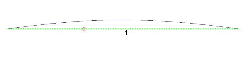
Later Generations of the WindomLater generation of the Windom are more correctly called off-center-fed dipoles (or in abbreviated form, OCF dipole antennas). Some people might take issue with using the word "dipole" because the antenna has more than two opposing polarities along the length, but in my opinion it is perfectly fine. Physics does have two-pole "dipoles" that are rigidly described as such, but not in the context of antennas. A dipole antenna is defined in many antenna engineering textbooks and dictionaries as an antenna that is insulated at some point forming two halves of no particular length. There can be short dipoles and long dipoles, sometimes well over 1/2 wavelength long. If it is good enough for people like Kraus, Jasik, and others to use the term dipole to describe a "two half" antenna of varying length, it is good enough for me. The problem with making a multiband OCF dipole is finding a sweet spot that presents a reasonable impedance on all amateur bands. As frequency increases the length of the antenna and offset of the feedpoint become critical. Along with critical length and feed line offset comes increased sensitivity to surroundings. Theory Behind The WindomEvery unterminated antenna has standing waves. In the context of standing waves, we actually are speaking of voltage and current distribution along the antenna. If we represent current levels with a line, a half-wave 3.5MHz dipole's current distribution looks like this:
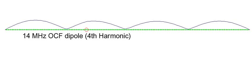
Notice the offset feedpoint does not distort the current distribution along the wire. Current is maximum at the center and minimum at the open ends. This means the feedpoint impedance is lowest at the center, with current increasing towards the ends. The impedance, if we break and feed the antenna with a two-wire source, is about 50-70 ohms at the center and very high (but not infinite) at the ends. By offsetting the feedpoint from the center we can increase the feedpoint impedance without upsetting current distribution or antenna pattern. The same "dipole" operated on 14 MHz (the 4th harmonic) shows four current peaks, or four "low impedance" areas along the antenna:
When there are multiple peaks in current, each current peak is less intense. Peak current at any point is less than with the same power applied to a half-wave. This of course means the impedance at each low impedance point (current maximum) is higher. The end-impedance is also lower! Notice in this case the dot representing the feedpoint was offset but very near the maximum.
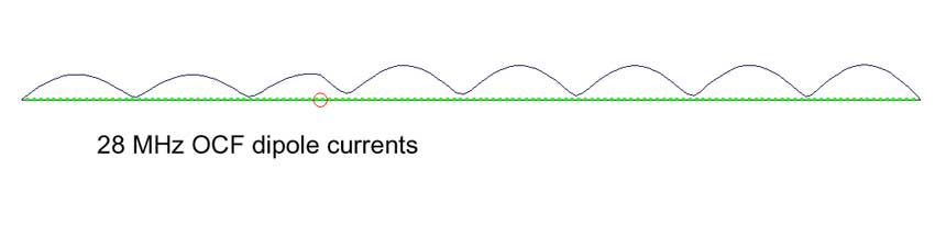
Finally at 28MHz we have this:
Notice once again the feedpoint falls very near a current maxima. Now there are 8 maximum current points. With a 137-foot long antenna we have eight maximums. This is one maximum every 17 feet. An 8-1/2 foot move in antenna length or feedpoint location takes us from a maximum to a minimum! This means we have to be very careful with antenna dimensions and feedpoint location or we could miss the maxima. The Windom or OCF dipole is a balancing act. We must position the feedpoint and select the antenna length to place the feedpoint at or near a current maximum at every desired operating frequency! The higher the frequency the closer the feedpoint must be to the center of the current maxima on that band. A large error or offset can be tolerated on the lowest band, but not on the highest band. This is because current changes very fast with physical position on the highest band, and because maximum current levels are lower than on the lower bands. Slight adjustments in antenna length and feedpoint location affect the highest bands severely.
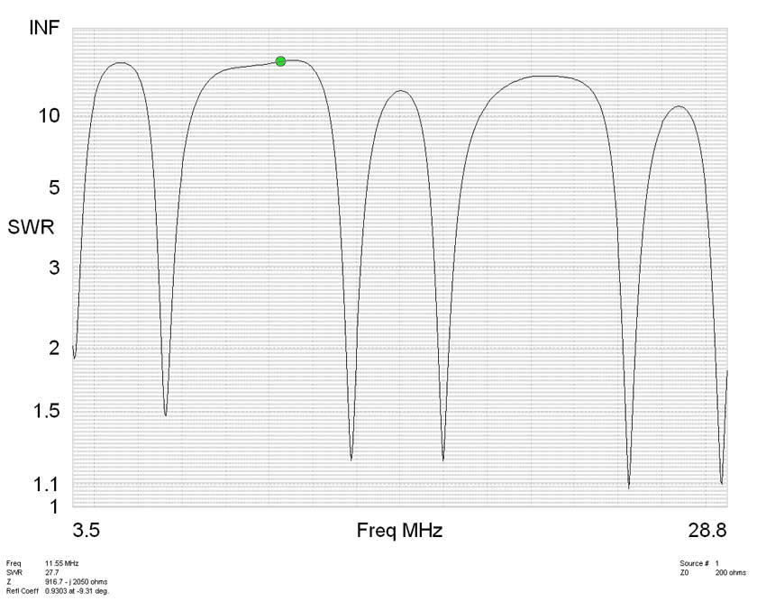
SWR Plot 80% Feedpoint OCF Dipole or WindomLike many people, I'd like to have one simple cheap antenna that handles 1500 watts, has a low SWR, and radiates efficiently on all primary HF bands. I spent a few hours of time modeling OCF dipole or two-wire feed line Windom antennas. This is the best combination I could find. Length: 137 feet of bare #14 to 16 AWG wire Height: As high and clear as possible Feedpoint: Located 80% from one end. 27.4 ft from one end. Here is an SWR sweep of this antenna:
As an alternative this antenna can be fed at the feedpoint with a good 4:1 current balun. Be careful doing this because many 4:1 current baluns are very poor designs. Some baluns advertised to be current baluns are not even current baluns! The following plot shows SWR using a good 4:1 current balun.
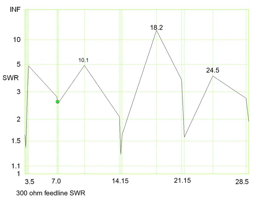
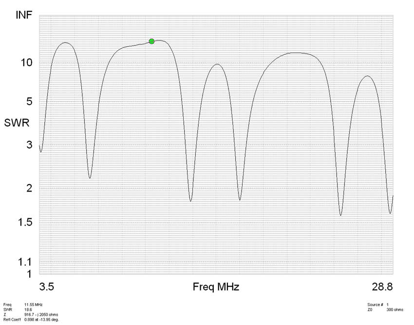
This provides a very useable antenna on 80,40,30,20,15,12, and 10 meters. The antenna is not particularly good where SWR exceeds 5:1. 60 and 17 meters are excluded from "good performance" bands. 66.7% Feedpoint WindomNote: This feedpoint offset gives up 30 meters. This is the primary reason I avoided the 1/3-2/3 feedpoint position and used the 80% feedpoint position. .The following 300 ohm plot shows 300 ohm feed line SWR. This is the SWR that would appear on a 300 twinlead feeder:
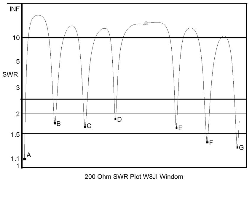
The 80% offset is better when using 300-450 ohm lines. The following 200 ohm SWR plot is for a Windom which is 1/3 and 2/3 offset, as shown in the ARRL Handbook. This is the SWR that would appear on a 200-ohm balun at the feedpoint:
c. W8JI 2006
.
|