Grid resonance
|
Grid resonance |
|
|
Also see
The single largest cause of VHF instability in amateur power tubes is grid-to-anode feedback. This even occurs in grounded grid amplifiers. Control grid construction, lead lengths inside the tube, sockets, and socket wiring to chassis ground dramatically affect grid impedance at higher frequencies.
One way to measure effectiveness of grid grounding is measuring S21 with the grid grounded. By applying a leveled source that sweeps frequency at the cathode and placing a sensitive detector at the anode, an isolation vs. frequency isolation level can be plotted. This plot will show the frequencies where the grid is not effectively grounded.
Directly grounded to chassis with shortest possible connection.
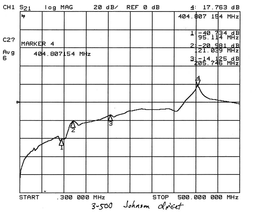
Notice low impedance dip at 95MHz, a peak at 121 MHz, and a reasonably broad increase in grid impedance all the way up to 404 MHz. Test have shown this tube/socket combination without suitable parasitic suppression can oscillate anywhere from 110 to 250MHz, depending on anode impedance and exact layout.
The Ameritron socket uses a ground plane to connect all grid pins. It has short wide socket connections. Here is the same tube with only a socket change.
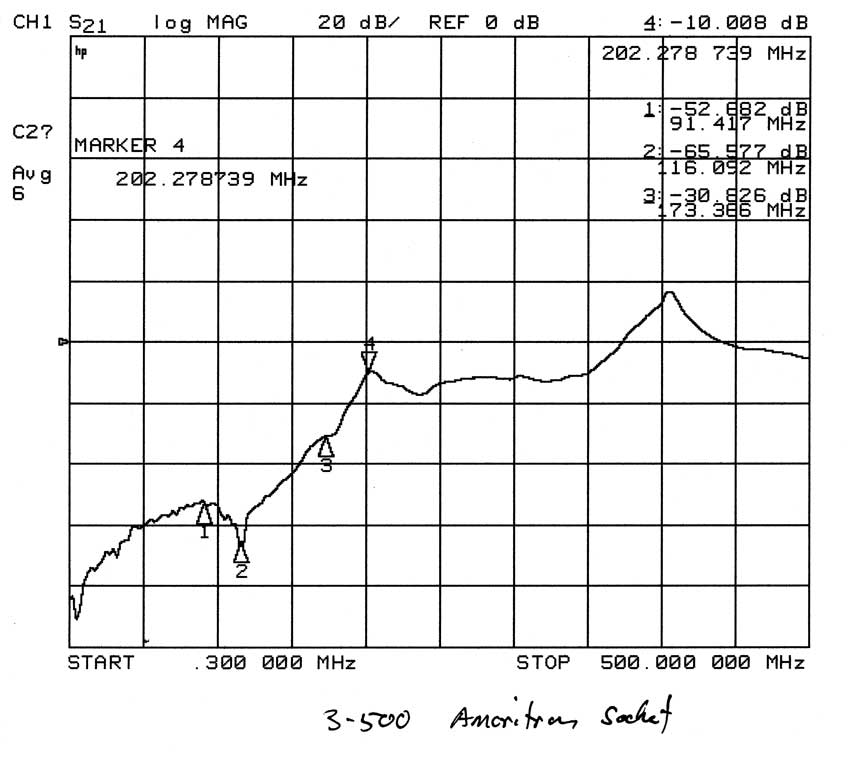
The grid is most ineffective ("parallel resonant") at 202 MHz. There is a series-resonance effect or low impedance at 116 MHz. Tests prove this socket and tube combination, without any anode parasitic suppressor, oscillates at about 200 MHz in the AL-80A or AL80B amplifier.
This arrangement is typical of amplifiers like the SB-220 and Kenwood TL-922 in that the grid is not directly grounded. The grid is grounded through 500pF capacitors with one inch of total lead length.
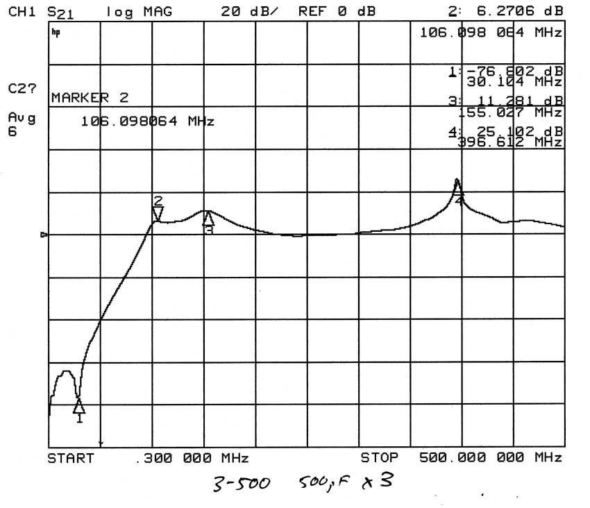
Notice the large increase in VHF feed through, indicating the grid is no longer effectively grounded at frequencies above 50MHz.
A suppressor with many more turns is required to stabilizing an amplifier with this grid arrangement. The grid is very well grounded at 30 MHz.
I attempted to use a grid dip meter to measure grid resonance. This In this only case where my GDO meter would dip.
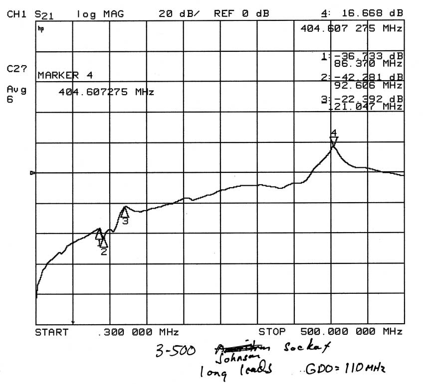
Again this is a poor grid connection arrangement, and the only one where I saw a reliable dip at the socket grid pins. In this case the amplifier could oscillate somewhere between 100 and 250MHz, depending on the anode system.
Reducing capacitor size to 33pF looks like this:

This creates a dip at 85MHz but at the cost of much poorer performance across the rest of the spectrum. This is not a good arrangement.
Of all these configurations the best is a direct connection from grid to ground with the shortest possible leads. This will make the least troublesome amplifier.
Here is the same test procedure with an 811A tube.
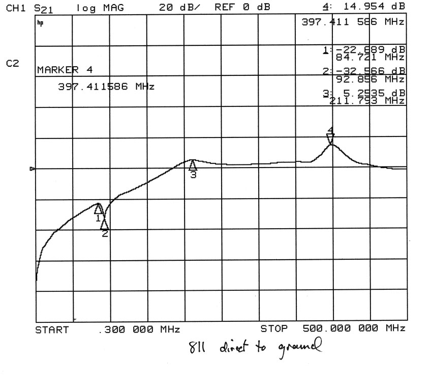
We can see the 811A has much higher feedthrough than a 3-500Z. The grid is poorly grounded through a long internal grid lead. The poor grid-to-ground connection makes the 811A tube much more difficult to stabilize. An 811A with long anode lead length tends to oscillate on 50-60 MHz. The 811A, with four tubes in parallel, is also unstable at HF without neutralization.
Here is an 811A with the grid grounded through a 500pF capacitor.
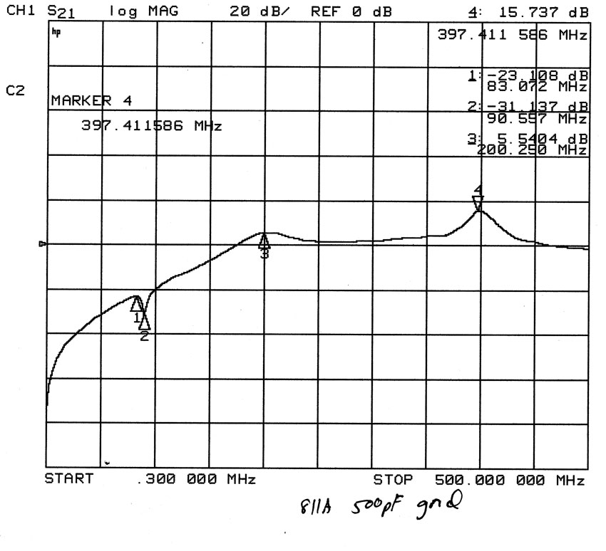
The 500pF capacitor doesn't make a great deal of difference because the grid is already poorly grounded.
Also see HF stability
©2006-2010 W8JI