rev AM April 15/12
rev PM Sept 23/11
While most areas of troubleshooting and engineering follow logical steps, a great deal of empirical or voodoo engineering surrounds amplifier instability. Few builders follow logical planned steps to understand, test for, and correct instability problems. Much of the problem surrounds the abstract nature of flaws causing instability, lack of visualization of component and layout VHF behavior, and the lack of good articles about causes of instability. The absence of readily available information creates a vacuum, and that vacuum causes builders to rely on some well-written but, regretfully, pathological science. When we couple the natural human desire to have a fast, simple, universal answer or simple instruction to solve every complex problem, we become targets for some very bad science.
The intelligent discussion of VHF systems requires a feel for VHF systems, and how VHF energy moves through a system. At VHF, wavelength is very short. Wavelength in feet is F/983.6, a typical 150 MHz system would have a quarter wavelength of 19.8 inches. This does not include velocity factor of dielectric, or unevenly distributed series inductances or shunt capacitances, which can make electrical distance along a conductor appear much longer than it is.
The general rule of thumb is two electrical degree length paths will have a negligible effect on system impedances. While that is 3 feet on 160 meters, two electrical degrees is roughly 1/2 inch on 150 MHz.
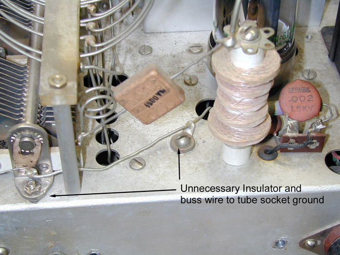
A 10-inch long conductor, in particular a thin conductor with a dielectric, is just like having no path at all for VHF, yet we see Internet suggestions of adding thin wires from grid pins up to tuning capacitors to beneficially alter the path from tuning capacitor to grid in some amplifier layouts! This is the same false notion Johnson engineers used in the Valiant and Ranger transmitters. In the image below, Johnson used a buss wire to ground tuning capacitors to the 6146 socket ground, which turns out to be a disaster for ground loops and VHF harmonic suppression.
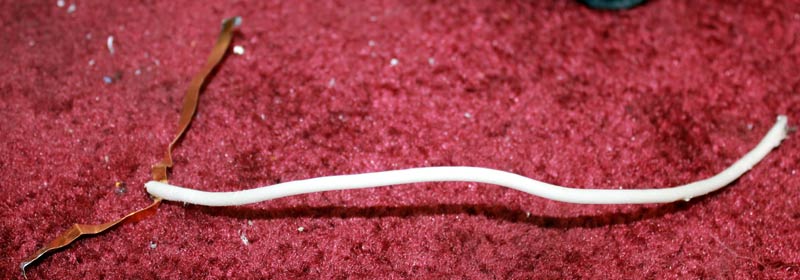
A similar fallacy exists in HF amplifiers, where people add an even thinner and longer wire from tuning capacitors to the grid pins of tube sockets. A Kenwood TL922 I worked on had just such a mod, clearly the installer had no idea about wavelengths and transmission line behavior. They used a thin wire several inches long, shown below, in an attempt to reduce tuning capacitor to grid path impedance!
VHF paths must be short and very wide, and ideally would be smooth surfaces. A wide path acts more like a groundplane, instead of a transmission line. For example, a 20-inch metal radius makes a very low impedance ground path at VHF, yet a 20-inch thin wire can look like no ground connection at all between two points! If we want reasonable results, we have to stop following unreasonable logic or junk science when making changes. If a tuning capacitor is poorly connected back to the grid at VHF, because the path through 10-inch wide sheet is too long, we are NOT going to improve it with an additional several inches length of .060 inch wide conductor in parallel. The notion something so thin in parallel with a wide ground plane helps reduce path impedance is silly.
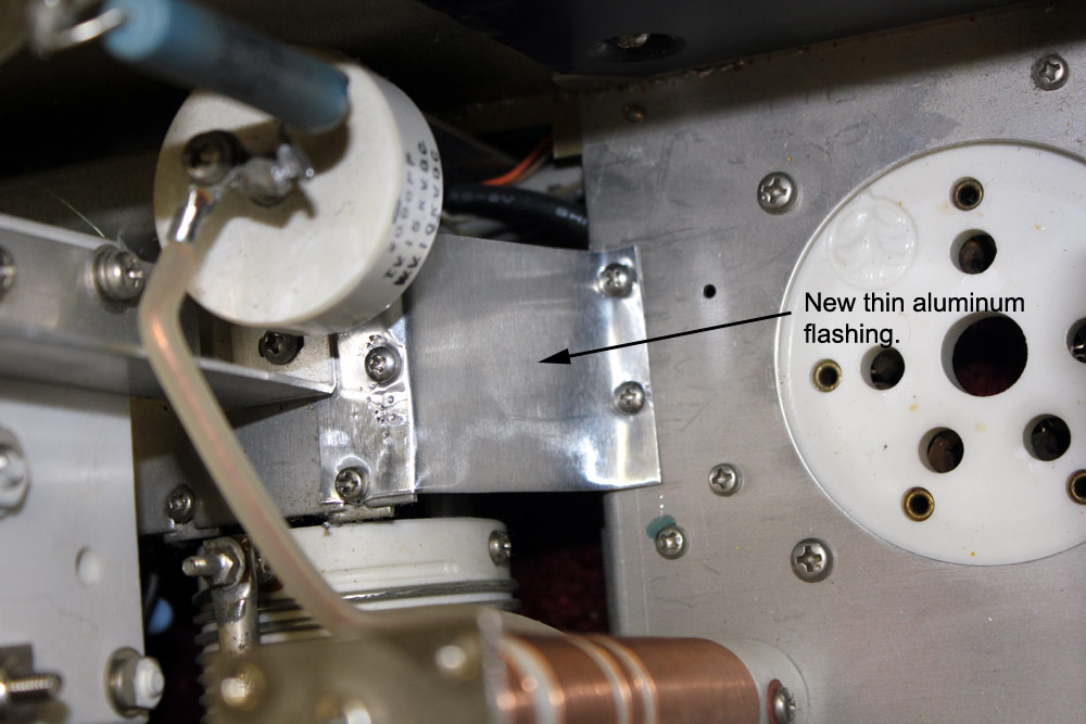
In the TL922, I used the chassis groundplane effect to advantage by adding a wide strap connection only a few inches long.
To actually improve things, we must stop treating VHF systems like they were DC systems, or HF systems.
A similar error occurs in a west coast amateur's discussions of VHF suppressors. He treats the VHF suppressor as an isolated component that solely determines anode system Q. The anode suppressor is actually one small section of a much longer path that behaves like a transmission line. The suppressor Q, in isolation, means very little to overall system behavior. We have to look at the suppressor in full context of how it modifies a much more complex system's overall impedance. This is why every suppressor, when optimized, must be optimized for a particular system. As we see when we look at commercial designs, one size does not fit all. In many cases no suppressor at all is required, and when required, depending on application and layout, a variety of styles are used. There is no single right way and wrong way.
We might assume, because of a certain circuit configuration or descriptive system name, the system behaves like that configuration on all frequencies. More often than not, there are exceptions to that assumption. Within a certain frequency range, things do behave as schematics and descriptions might indicate. Beyond those frequency limits things change. Let's consider the case of a grounded grid amplifier.
A grounded grid amplifier only acts as if the grid were grounded over a certain range. The range where the system behaves as expected is determined by how the grid is grounded, both with components and wiring the builder or designer can control, and by things inside the tube that only the tube manufacturer can control. Grounded grid amplifiers are theoretically unconditionally stable, because they have extremely high negative feedback from output-to-input. This negative feedback, determined by the ratio of output load impedance to input impedance, normally swaps out any regeneration. The grid or grids, in theory anyway, also shield the input from the output.
Unexpected problems occur when the system does not behave as the schematic implies. This is because the schematic does not show stray impedances. These stray impedances can reconfigure the amplifier stage on various frequencies, making it change modes anywhere from stable grounded-grid operation, to a mode where the grid floats.

These capacitance ratios are loosely typical for most transmitting tubes. The grid-to-chassis impedance is why the anode-grid path, not the plate-cathode path, dominates VHF stability.
At HF and lower, a different effect can occur. The plate-cathode feedthrough can allow regeneration from anode to cathode. At high frequencies with long thin grid leads, the might not appear grounded at all.
This mixture of effects varies with input and output networks, layout, tube, socket, and wiring.
For the 8877, published capacitances are:
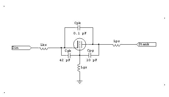
The large area grid, with very close spacing to the cathode, causes abnormally high cathode-to-grid capacitance. This capacitance actually helps stability, because it holds the grid closer to cathode potential.
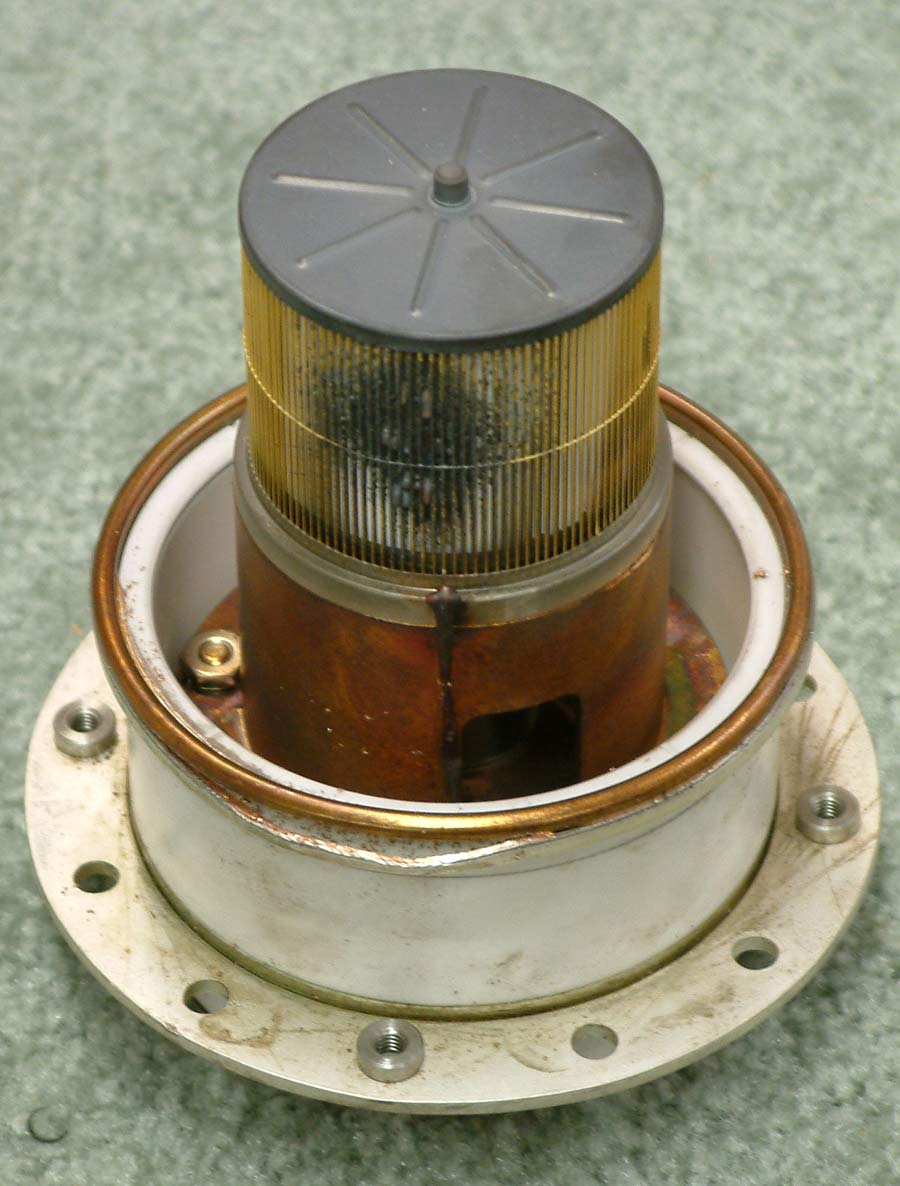
The dominant reason the 8877 is so stable is the cone-type grid support structure that exits the envelope through a large area flange. If the grid flange is directly grounded with a very short chassis ground, grid impedance is so low that the 8877 is unconditionally stable without any suppression at all.
The very same things that allow a tube to be a good amplifier tube on VHF and UHF make it a stable tube at HF. The least stable tubes are those with poorest VHF and UHF performance. If a tube is useful and stable at VHF or UHF, it will be even more stable in a properly laid-out HF amplifier system.
When the impedance of Lgs becomes large enough, either resistive, inductive, or capacitive, the tube is effectively no longer in grounded grid operation. We now have the makings of a TPTG oscillator, with feedback through Cpg.
This is why it is important to ground the grid as well as possible. Look at the changes I made in a TL922 grid system. The same applies to the SB220.
The most sensitive control element in the tube (the control grid) generally has the largest influence in determining oscillation frequency. The grid often controls if, when, and where the system oscillates. Small changes in control grid (and screen grid) voltage, with respect to cathode, dominant tube operation. This is why primary frequency control elements of VFO's or crystal oscillators are normally placed in the control grid's circuitry.
The anode system normally has the highest RF voltage swing in the system. The anode-cathode path through the tube has the largest time-varying current, the current being primarily regulated by the control grid. If the anode system presents a high impedance at radio frequencies, small changes in anode current will cause significant RF voltages to appear. With large anode voltage changes for relatively small anode current changes, a very small amount of anode-to-grid capacitance can be enough to form an oscillator. Logically, the grid-anode path and circuitry at the grid and anode by far are most likely to dominate an unwanted oscillator system.
An oscillator also must have enough gain to overcome feedback loss, and feedback has to be the correct additive phase. If positive or regenerative feedback does not exceed system losses, the system cannot oscillate. The control grid-to-anode path generally has the highest possible unwanted gain in the amplifier system, and that is why this part of the system is (by far) the most problematic area for unwanted VHF stability problems in lower frequency amplifiers. The normal mode of VHF oscillation in HF PA's is where the tube becomes a tuned-plate tuned-grid oscillator. The frequency of this oscillator is mostly determined by the grid system, from the grid inside the tube, out through the grid terminal, to whatever is outside the tube.
The control grid system has considerable stray capacitance to the cathode and other low VHF-impedance elements. The control grid also has a conductive path connecting the grid to the socket grid pin. The combination of grid-to-ground shunt capacitance and grid-to-ground series inductance through the grid lead-to-chassis path forms a parallel resonant circuit with fairly high Q. Since this circuit mostly exists inside the tube, there is very little we can do externally to reduce grid impedance at very high frequencies. Most of that impedance is inherent in tube construction. Every grid, deep inside the tube, behaves like it is connected to the grid pin or grid ring through a parallel-tuned circuit. At some frequency, internal grid stray-capacitance parallel-tunes the total inductance of the grid-to-ground conductor path.
L1 and C2 primary determine optimum frequency for unwanted oscillations. The parallel resonant combination of L1 and C2 "float" the grid off the chassis. Unfortunately we cannot greatly affect L1-C2, they are mostly inside the tube. Optimally, L1/C2 should be resonant as far above the highest desired working frequency as possible. L1 should have the lowest possible impedance below the operating frequency.
L3/C4 (including the C3+C6 path and C5 path) allows the anode to easily change anode voltage at VHF with small current changes inside the tube. We want L3/C4 to be resonant below the grid resonant frequency, with the lowest possible reactance. Ideally we would want the anode to see zero impedance at the frequency where the grid is resonant, but that is impossible. The next best choice is to load the anode with a perfect termination, like a dummy load, that has low-to-modest resistance to ground. For maximum operating efficiency we want L3 to have minimum series resistance at the desired operating frequency.
The unwanted VHF feedback path, creating an undesired oscillator is through C1.
Anode system path
The anode has stray capacitance to chassis and to grid
The long RF connection from anode-to-chassis has series inductance. This is the anode's "VHF tank coil"
Stray capacitance from anode-to-ground parallel-tunes the anode wiring's inductance
This forms a complex resonant circuit with the anode components and anode capacitance
Let's measure a typical amplifier and see what impedance the tube looks into when the tank is tuned and terminated in 50 ohms.
On twenty meters, the anode system of the above amplifier has at least 5 resonances between 500 kHz and 500 MHz! This is typical for almost any HF amplifier using a physically large tank system, especially with large air-variable capacitors. The highest impedances appear in the broadcast band, and at the operating frequency (right side of Smith chart). Lowest impedances are at low-order harmonics. This is necessary for harmonic suppression.
Some people claim they can put a grid dip meter near the anode lead and tell us everything about the Q and frequency of resonances. This is clearly untrue, because they also falsely claim the resonant frequencies never change as the band or tuning are changed.
The marker is set on the only frequency range where, when the parasitic suppressor is removed, this AL80B oscillates.
In the AL80B, on twenty meters, the anode looks into an impedance like this:
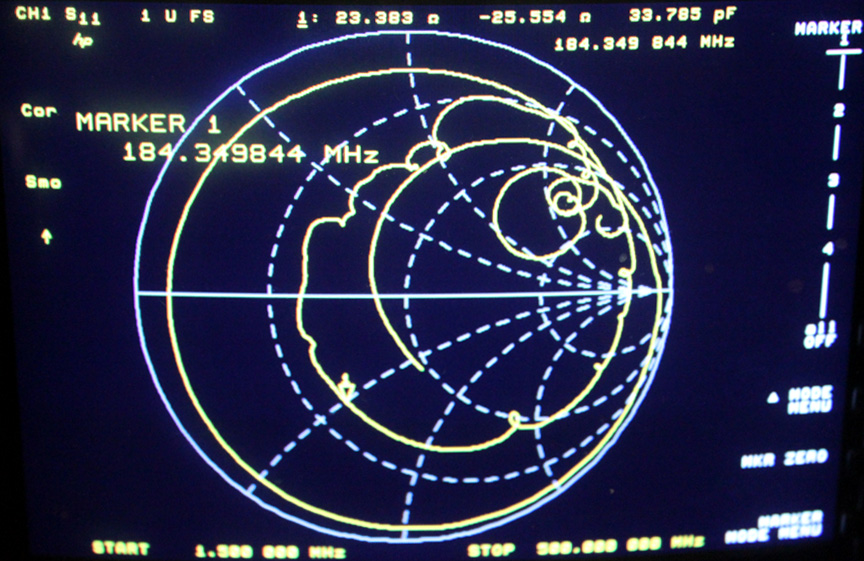
Note, at the frequency where a 3-500Z typically oscillates, impedance is 23.4 -j25.6 ohms. This is a Q of 0.9
Despite this low Q, some people suggest "low-Q" nichrome suppressors are the only fix for all problems. Adding a nichrome suppressor to the AL80B actually increases VHF Q, while decreasing desirable HF Q of the anode system.
Avoid magical gimmick systems, you are just likely to make things worse!
Neither Eimac, nor any large scale experienced amplifier component or equipment manufacturers in the world, suggest a reduction of HF Q is necessary or desirable.
On 15 meters, the impedance changes, even at VHF!
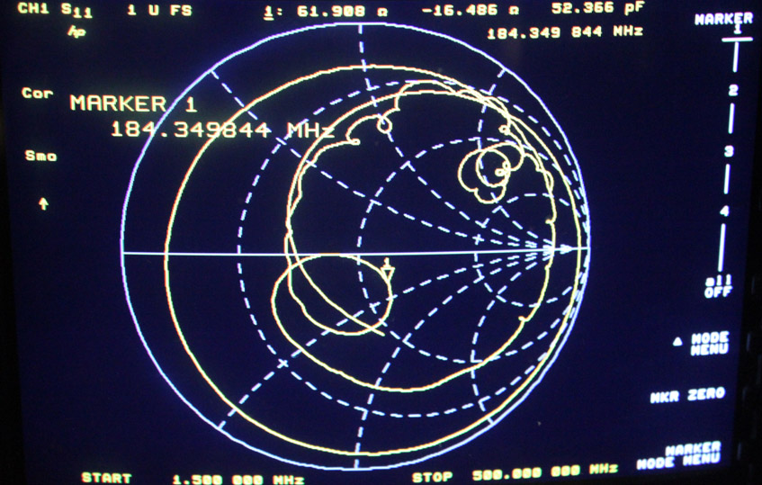
Notice how the trace near the 184 MHz marker, as well as all over the chart, has now changed. The AL80B now has six resonances.
Again, multiple variable resonances are typical for most HF amplifiers. They are not in the least harmful, and are actually unavoidable. They have little to no significance in operation. The only requirement is the amplifier have adequate harmonic suppression, and pass stability tests.
This is why the PLATE and LOAD, as well as the BAND switch, must be rotated through all positions to verify amplifier stability. My stability testing procedure does just that.
Grid system path
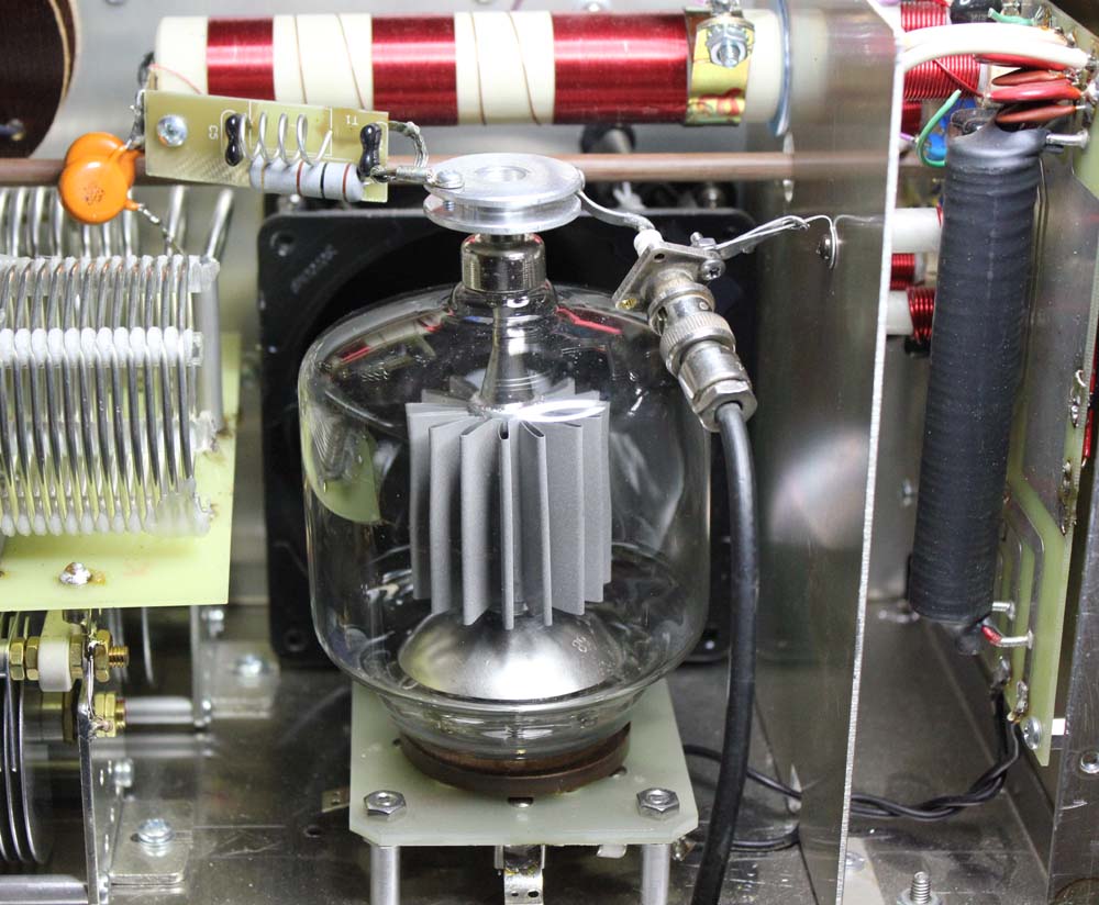
The 3-500Z control grid is a moderately good design. It has three grid pins (all three should be grounded), a wide grid support, and about 2" of total height above the glass base. The outer cage is the grid, and the inner spirals are the filament helices. The upper end of the filament helices weld to a vertical rigid support rod:
The grid has inductance in the connection path from grid-to-chassis. This is the grid circuit's "VHF tank coil"
The grid has stray capacitance to chassis and filament. This parallel tunes the grid's inductance
The grid also has significant internal capacitance to the anode which forms the unwanted oscillator's primary feedback path
With all of this, the circuit has everything needed to become a tuned-plate tuned-grid oscillator if tuning and feedback conditions are right.
If feedback loss (attenuation) from anode-to-grid capacitance is less than tube gain at some frequency, the tube may oscillate. The final requirement is the phase of unwanted feedback must be an angle value that produces regenerative or positive feedback. These requirements are the same in any oscillator.
The cathode drive system is normally not part of VHF instability. With a proper input system, the cathode system has low enough impedance to be considered "grounded".
The suppressor, Rs and L1, in combination with the existing anode path Z, becomes the anode-to-chassis path impedance. This forms the plate load resistance at every frequency. The impedance must be analyzed at every frequency.
The grid path impedance can also be varied, and again must be analyzed at every frequency of concern.
In a grounded-grid amplifier, grid Z should be as low as possible at every frequency.
For maximum stability we want the resonant frequency of the anode, at every frequency where there is significant internal tube gain, to be lower than the resonant frequency of the control grid.
Conditions for Instability
Once again, the conditions required for instability are:
If any one of the above four requirements are not met, the tube will not oscillate! This is true no matter how high Q is in any individual path, or if the tube has suppressors or not. What this means is, we cannot just look at "Q". The problem, while we would like it to be simple with only one possible cause and one universal solution, really involves four distinct but easily understood areas. This is the same with any oscillator, whether the oscillator is desired or unintentional!
The Myth of Parasitics Causing Bandswitch and Tube Failures
Claims have been made that tubes will remain stable for years, and a "sudden event" (like a photon striking a tube) will make the tube break into an uncontrolled oscillation. Oddly, these claims all come from one source with nothing but the fact "something bad happened" as evidence of parasitics. His evidence of a cure is someone installed his kit and was happy. This is like the tactic Gotham used for selling antennas.
We all know, or hopefully we understand, that oscillators are oscillators. Oscillations that start cannot stop unless one or more of the four important system parameters above significantly change. Also, an uncontrolled oscillation cannot suddenly start, especially one that has so much feedback it reaches catastrophic levels, unless all of the above conditions are met. These conditions are either met, or they are not met, unless we change something. The notion a healthy system can go along for hours, weeks, or years and suddenly break into an uncontrolled oscillation that damages components is highly unlikely unless a major component significantly changes characteristics.
Conversely, if the system is stable, one or more of the above parameters must change in a way that allows oscillation. If that happens the tube will oscillate continuously until operating voltages are removed. We can actually intentionally try to create optimum oscillation conditions. I do that to test for stability. Even creating intentional oscillations, nearly all of the time, oscillations are not damaging.
Exploding VFO's Anyone?
Consider the oscillator in a transmitter. The oscillator rapidly comes up to a state of equilibrium and stops increasing in amplitude. We never find an oscillator that can output more power than the same tube can provide operated as an amplifier, as a matter of fact power is always less!
Any claim an amplifier tube that saturates at a few amperes cathode current can provide 50 or more amperes of "big-bang" current from accidental oscillation is profoundly ridiculous. The cathode can't magically produce more current as an oscillator than the saturated emission would permit in any other service. Such big-bang claims might make good fictional theater, but they aren't factual.
The most common effect of unwanted VHF oscillations are creation of spurious signals and odd meter readings; not bangs, pops, or arced band switches. Bangs and pops are caused by gassy tubes or other problems, while arced bandswitches (if caused by an oscillation) are generally caused by oscillations at or near the desired operating frequency!
Most of our modern PA's are grounded grid (cathode driven). Cathode driven operation requires that one or more grids be directly grounded to the chassis (at least for RF) with the lowest impedance possible. This is necessary to shield the output from the input, and assure operating frequency stability and purity of emissions.
A VHF oscillation, if it happens to occur in an HF PA, is almost always rooted in the system behaving like a "tuned-plate/tuned-grid" oscillator. To be most effective, a VHF suppressor must be located between the tube element and a low-impedance path to ground at VHF. This allows the best loss-loading of the unwanted internal oscillator circuits. The actual working circuit causing a VHF oscillation is almost always entirely different than what appears on the actual component-based schematic. The cathode, an element commonly involved in low-frequency instability is rarely involved in VHF oscillations, other than supplying electrons and stray capacitance to ground.
Even though the anode is the second most problematic area, it is an area most easily altered and modified. This is because virtually every anode has much shorter and wider connection paths to outside tube terminals. Suppressors are normally found in anode systems, even though other locations can work to suppress oscillations. Locating the r suppression in the anode path generally works best because the grid or grids can remain well-grounded for RF, provided the best operating frequency performance, and because the anode connector is often the shortest access point to tube internals.
To be most effective, the suppressor has to dominate the anode path impedance to chassis. This means the suppressor inductance must be large compared to anode-chassis path impedance. Short and wide anode leads, a low VHF impedance plate tuning capacitor that is well-grounded to the main chassis, and compact layout, work in concert to minimize required suppressor inductance.
The most problematic tubes for VHF oscillation have relatively large elements and long thin leads. Tubes of this type have low gain or are unusable at VHF. This is because elements in the tube (shunt internal capacitance combined with series lead inductances) are actually resonant or connected to outside pins through high VHF impedances.
Internal connecting leads diameter and length are almost always the major concern for parasitic instability. Longer and thinner internal (and external) leads produce less stable and more difficult to use tubes. Long and thin leads move a tube element's natural self-resonance lower in frequency and increase element impedances. This causes unwanted self-oscillation even with tiny amounts of anode-grid feedback capacitance.
Looking at the above, tubes with thinnest and longest leads are most troublesome. These tubes also provide poorest intentional VHF performance.
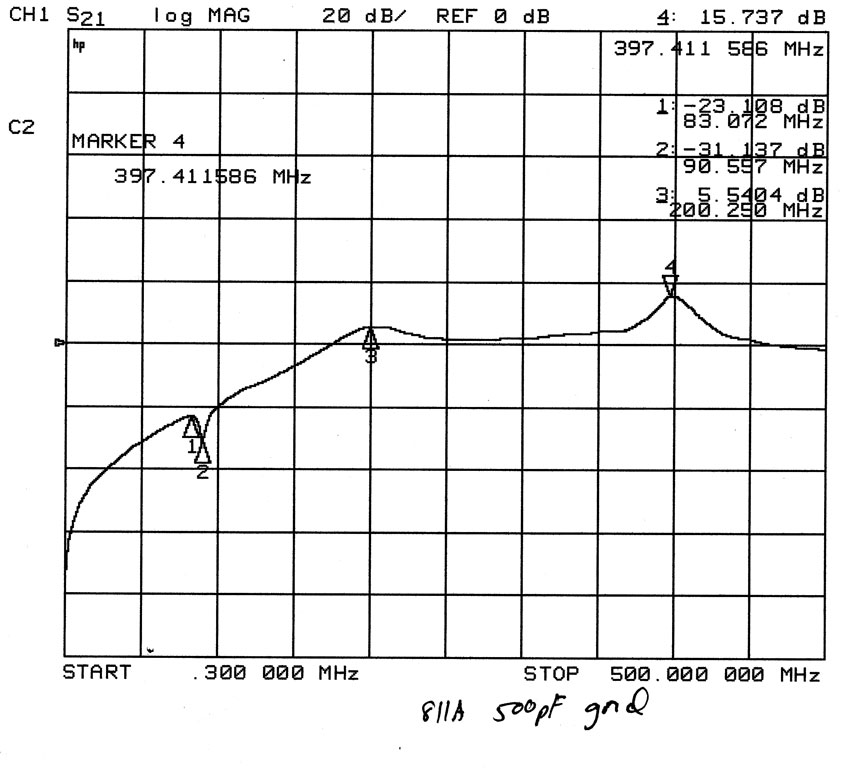
The most troublesome tubes listed above tend to oscillate in the lower-VHF range, between 40 and 120 MHz. The typical instability frequency of an 811A or 572B is around 80-100 MHz, assuming grid leads are short and direct to the chassis.
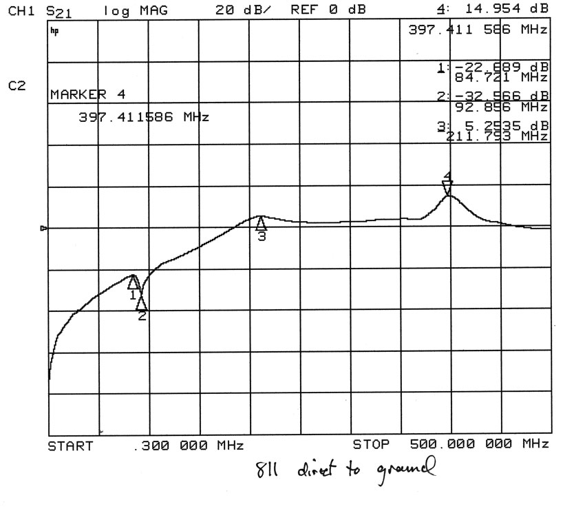
The plot on left is the feedthrough loss of an 811A tube in a shielded test fixture. The tube can oscillate on any frequency where loss is around -25 dB or less.
Adding series capacitors from the grid to ground does not help, the result is essentially no change. If the capacitor is too small, or the leads too long, things get worse:
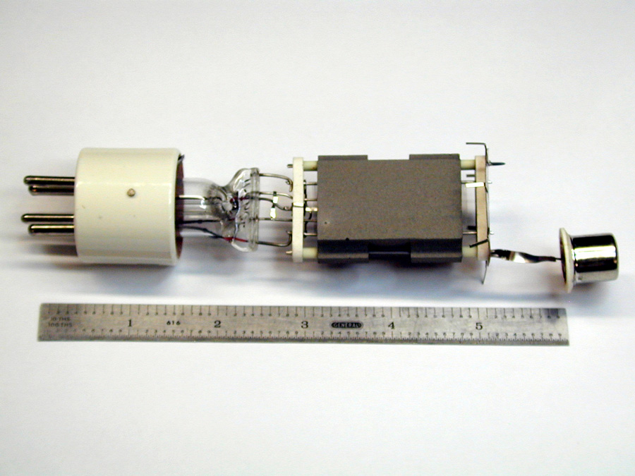
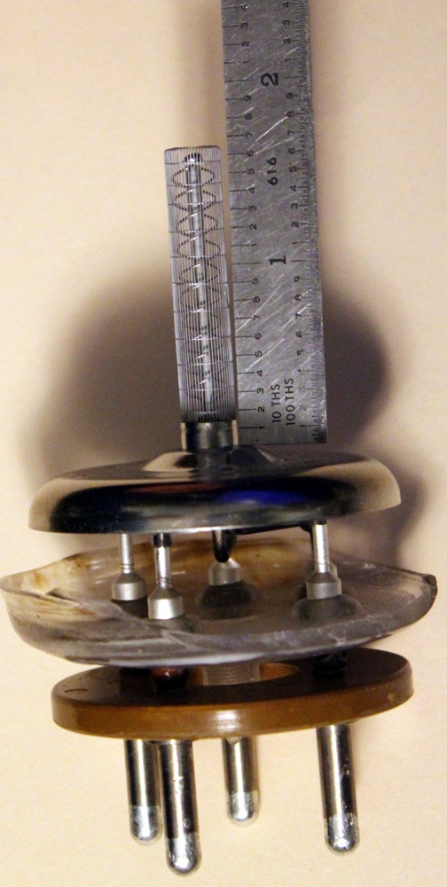
Note the 572B tube on left has very long, thin, grid leads. There are three inches of very thin wire to get a chassis ground connection to the control grid! This tube is typical of 572B and 811A triodes.
This tube was not designed with high frequencies in mind. For higher radio frequencies, the second thinner socket pin could have provided an additional parallel grid connection. The grid could have used much heavier and shorter internal leads.
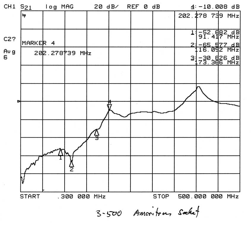
Moderately stable tubes tend to oscillate at 100-200MHz. 3-500Z's, for example, generally are most unstable from 150-200 MHz.
A very important thing to remember! The closer a tube's instability frequency is to the operating frequency, the more likely it is to have tank-damaging oscillations. This is because the tube might actually oscillate on or very near the tank circuit's resonant frequency. It also is much more difficult to stabilize a tube with a low grid-frequency resonance without severely impacting desired operating frequency efficiency and gain.
Anode circuit layout can contribute to VHF instability. Long thin leads from the tube anode connector to the chassis at VHF are a problem. Problems can occur when thin (and long) plate blocking capacitor leads, thin and/or long wiring, and poor mounting of the plate tuning capacitor are used. The anode path, from tube through blocking capacitor and through the plate tuning capacitor to the chassis, is also an important VHF path. This is true even if the amplifier only intentionally operates on HF.
To maximize stability:
The grid circuit layout is probably the single most important area for insuring a stable design. Long thin leads from the tube grid connector to chassis are a problem at VHF. Problems often occur from physically thin and long bodied grid capacitors or thin and/or needlessly long grid wires or wiring. The best idea is to ground grids directly to the chassis through ground lugs mounted directly on the chassis immediately adjacent to grid pins. Always think "zero length grid leads"!
To maximize stability:
The parasitic suppressor normally has two components in parallel, a resistor and an inductor. At low frequencies, the path through the inductor dominates the system. At very high frequencies, the resistor dominates the system (assuming it is a low-inductance resistor).
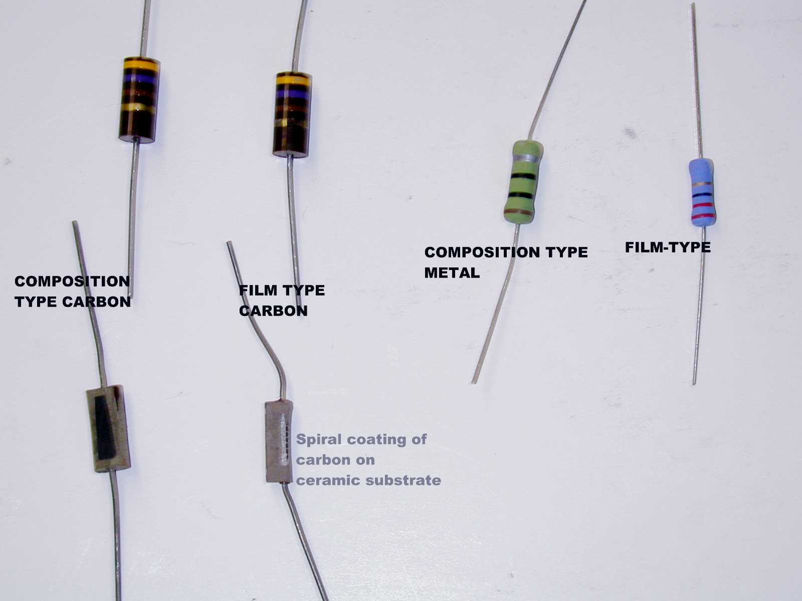
One common problem is people assume brown carbon resistors are non-inductive. That isn't the case. For an example, look at the following resistors:
I have non-inductive resistors suitable for VHF suppressors.
Old Parasitic System AL811H
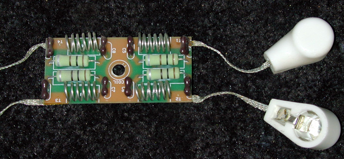
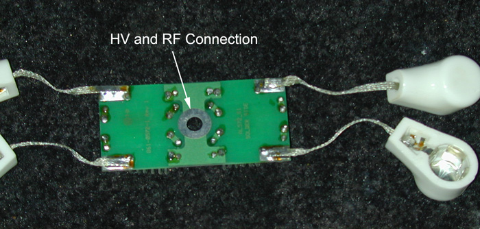
The photo below shows the original standard parasitic suppression system used in the AL811H amplifier:
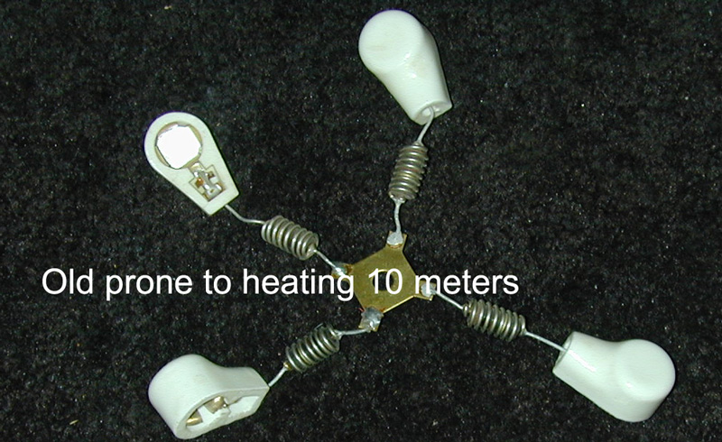
All of the spiral-conductor resistors above have significant inductance at VHF, and make very ineffective suppressors unless the reactance is cancelled. Only the true carbon composition resistors are useful in non-resonant standard suppressors.
This is a typical suppressor system, including inductance of the anode lead:
In this case V1 represents the tube. The following is a simulation of currents in the suppressor:
Starting at 30MHz, the ratio of current in the inductor to current in the resistor is:
Frequency -I(L1)
-I(R1)
30MHz
0.0047
0.0015
60
0.0041
0.0026
90
0.0034
0.0034
120
0.0029
0.0037
160
0.0024
0.0041
190
0.0021
0.0042
220
0.0018
0.0043
This tells us something very important. The INDUCTOR dominates only at low frequencies. At 30MHz, current in the inductor is three times current in the resistor.
At 190MHz, in the range of the instability frequency of a 3-500Z, the resistor has twice the current as the inductor.
This tells us any changes in INDUCTOR design or inductor Q (such as use of nichrome wire) mainly lowers low frequency Q. It would have virtually no effect on very high frequency Q of the system.
This has been my point all along with the Measure's nichrome suppressor. Measures claims, incorrectly, his suppressors provide lower VHF Q while, in fact, they do exactly the opposite! A typical Measures hairpin suppressor actually produced significantly higher system Q in the anode of a 3-500Z (nearly twice the VHF Q), because the equivalent Rp of the suppressor in series with the anode lead was lower!
The reasons HF PA's arc are explained at other pages of this site, and include incorrect relay sequencing, load faults, as well as improper tuning and exciter transients.
If we want a lower VHF Q, while maintaining high LF Q and efficiency, the system must shift current into the resistor faster as frequency increases. The suppressor must also have higher Rp, so it dominates the anode path inductance that is in series with the suppressor.
While Measures openly touts his "low-Rp suppressor", the fact is a low Rp suppressor results in higher anode system Q!
In order to improve VHF stability by reducing VHF Q and reduce VHF gain, we must have a series resistance dominate the anode system's impedance at VHF. This means, in a frequency sweep simulation, the ratio of currents in the resistance to current in the inductance must be as high as possible. Let's call that slope the rate of transfer.
The rate of transfer can be increased by adding a small value of capacitance in series with the resistor:
The old suppressor was:
Frequency -I(L1)
-I(R1)
Ratio
30MHz
0.0047
0.0015
3
60
0.0041
0.0026
1.6
90
0.0034
0.0034
1
120
0.0029
0.0037
.78
160
0.0024
0.0041
.58
190
0.0021
0.0042
.5
220
0.0018
0.0043
.42
The new one:
Frequency -I(L1)
-I(R1)
Ratio
30MHz
0.0069
0.0026
2.6
60
0.0050
0.0055
.9
90
0.0027
0.0052
.52
120
0.0019
0.0050
.38
160
0.0013
0.0048
.27
190
0.0011
0.0047
.23
220
0.0009
0.0047
.19
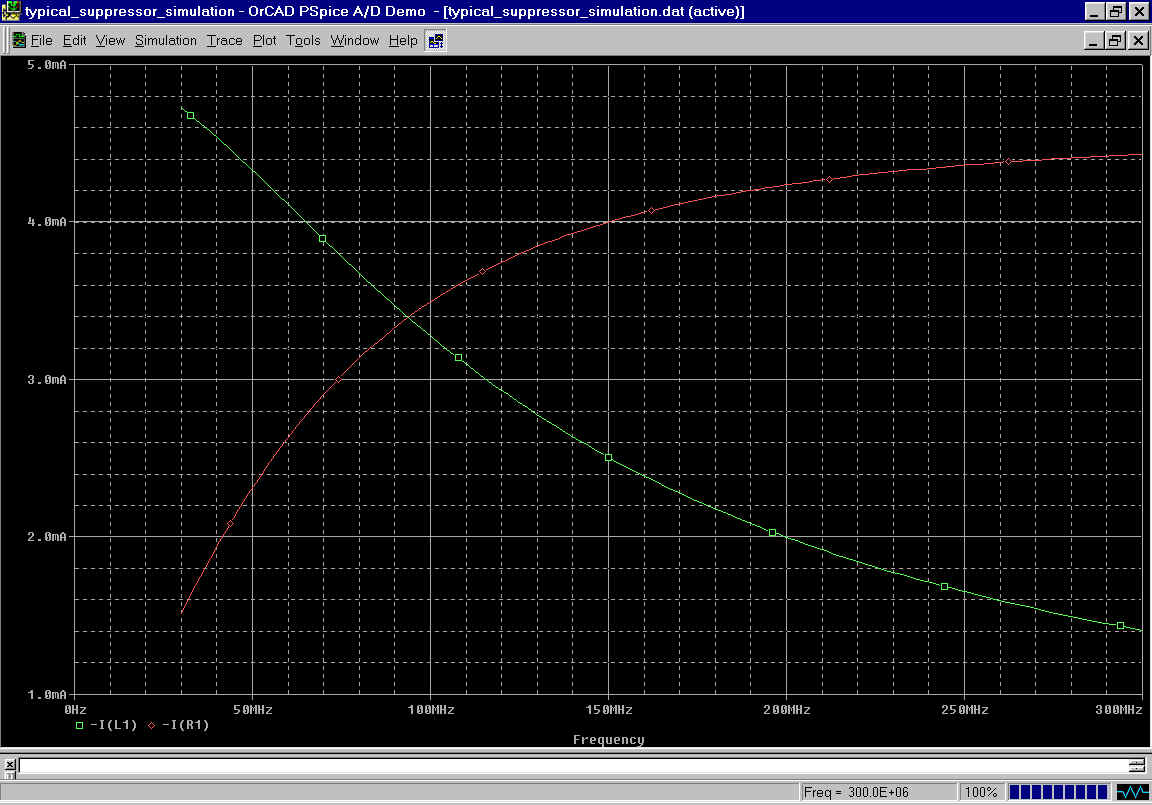
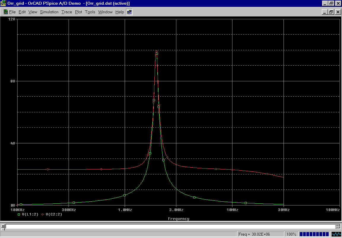
Graphically we see the currents are:
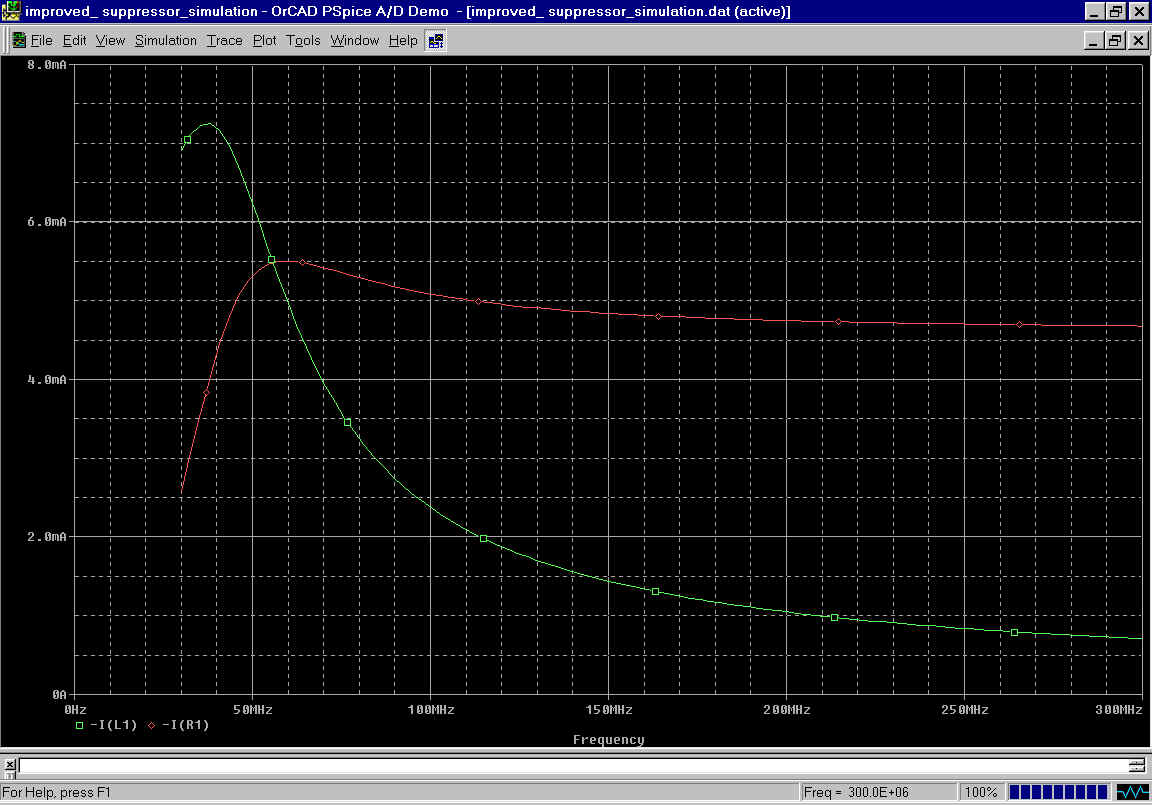
The green curve is current through the inductor, the red curve shows current through the resistor. Notice how flat current is in the resistor, and how sharp roll off of current in the inductor becomes.
This means we will have very low anode SYSTEM Q starting at a low VHF frequency of 50-60MHz, and continuing up to UHF. Dissipation in the resistor is still reasonable at HF, efficiency and tank Q at the operating frequency remain high, yet VHF suppression is greatly improved.
Optimum resistor value can be determined by network analyzer measurements, or determined empirically.
If the anode path to chassis is long and thin, the VHF impedance will be very high. A high anode path impedance (thin or long leads) requires higher values of resistance, because we want the resistor to dominate the anode system impedance. The best value for a resistor is generally one that is approximately equal to, or slightly higher than, the anode path reactance at the frequency of instability. This ensures an upper-VHF Q approaching 1, and a broad dampening bandwidth.
That impedance can be measured on an impedance test set, or through other methods by creative engineers or technicians. As a general rule in good HF tank systems, long, thin, anode leads (i.e. 811A's) require 100-150 ohms of resistance while shorter thicker anode leads (i.e. 3-500Z) require 30-100 ohms of resistance. Stable tubes with external anodes can often use natural anode lead resistance of brass or other materials, or even hairpins, to adequately dampen anode path reactance. Exceptionally stable tubes with short internal grid leads exiting on a grid ring often require no suppression at all, if the grid ring is grounded directly to the chassis.
At the frequency of instability, the suppressor inductor must present significantly higher reactance than suppression resistance values. The high inductive reactance causes the majority of current to flow through the suppressor resistor at very high frequencies, not through the inductor.
Looking at amplifier designs, we will find tubes like 811A's generally have higher resistor values and many turns in the suppressor inductor. Tubes like 3-500Z's have significantly fewer turns, especially when grid leads are kept very short and direct to the chassis, and can use lower value resistors.
One way to view this is to consider the frequency response of a Hi-fi amplifier. Larger values of plate load resistors in amplifier stages reduce higher-frequency gain. The same is true in RF power amplifiers. Lower frequencies of instability require larger inductors, so the RF path is shifted over to the resistor at a lower frequency.
Series-resonant suppressors are used with slightly inductive resistor paths, and larger-than- normal shunt inductors. A small capacitor is placed in series with the slightly inductive resistor path, and this capacitor series-tunes the resistor path to a very broad VHF resonance. This results in a very rapid shift of current into the resistor as frequency is increased. This works well with amplifiers operating at 1/3 to 1/2 the instability frequency. It minimizes resistor heat on upper HF while providing perfect lower or mid-VHF stability.
Typical amateur applications for shunt L series R-C suppressors are 3CX1200A7 and D7 tubes, 572B tubes, and 811A tubes.
Shunt suppressors with series-resonant tuning to ground are also sometimes used, the normal application is very high power stages with substantial anode-to-tank currents. These suppressors consist of a series R/L/C system, where the C is normally just stray capacitance to the tube anode. Sometimes these suppressors take the form of a ferrite block placed between the anode and chassis. The inductance of the block series-tunes stray capacitance, and the losses act like a damping resistance in series with the anode-to-chassis path. I've stabilized 50-100kW VHF transmitter designs using shunt suppression.
Some PA systems are prone to oscillation at low frequencies. Yaesu and Dentron amplifiers using 572B's, and the Collins amplifier using 811A's are good examples of production amplifiers with stability problems. These amplifiers tend to oscillate NEAR the operating frequency. All of these amplifiers, except the Yaesu, use tubes with high anode-to-grid feed-through capacitance and no neutralization. Worse, the Collins floats the grids for RF, reducing the already poor isolation of anode-to-cathode feedback path in the 811A.
Yaesu uses one of the poorest engineered feedback systems of all, with a capacitor from the output of the pi section back to the cathode! Phase shift in that path would vary wildly with tank circuit tuning and load impedance on the PA, as would the amount of feedback!
The Yaesu amplifier is a particular problem with Chinese 572B tubes, because grid mu is lower. Negative grid bias has LESS of an effect on cathode current, so the Chinese (and Russian) tubes draw extra quiescent current when the antenna relay is open. This additional current allows the tube to amplify while the amp is in standby. Since the antenna and input source are removed in standby, and the improperly designed feedback path to the tank output remains in place, the PA oscillates near the operating frequency with no load! Voltage in the tank builds up to many thousands of volts because energy is not extracted to a load. The fact the oscillation is at a low frequency allows the bandswitch to see the full voltage, and it often fails.
Amplifiers can create extremely large voltages when RF is applied and a load is not present!
All of the amplifiers discussed above would be greatly improved by:
Floating grids on capacitors to add "negative feedback" is one of the worse things every done in grounded-grid triode PA's . This bad idea appears in the Collins 30L1 811A amplifier, and Japanese manufacturers copied the bad idea into their power amplifiers. Heathkit was also a victim of this engineering gaff in the SB-220 and SB-221 amplifiers. Here is how it started and filtered through Ham gear:
When I was designing PA's in the late 70's and early 80's, an employee of Eimac (who was also an author of many articles and a popular Radio Handbook) put considerable pressure on me to float the grids of 3-500Z PA's through small mica capacitors. He called the circuit a "super-cathode driven" amplifier. He wrote letters and called frequently, asking why I would not float the grids through small mica capacitors.
This quite likable fellow creatively "borrowed" this idea from the Collins 30S1, which was actually a proper application for this type of system. This system works in the 30S1 because it is a cathode-driven class AB1 tetrode. The 30S1, unlike later "copy-cats" using the floating-grid circuit, has zero control grid current. The grid has very high impedance all through the RF cycle. The high grid-cathode impedance does not shunt the upper capacitor divider with the low drive-varying grid resistance of stages with control grid current. Essentially R1 (see the circuit below) is infinite in the Collins 30S1. The 30S1, unlike triode copy cats, has a directly grounded screen. The screen shields the RF input (cathode) from the RF output (anode).
The theory seems pretty simple on the surface. Floating control grids through small mica capacitors forms a capacitive voltage divider, with the small grid-to-ground bypass capacitors forming the grounded half of a capacitive voltage divider. The small internal cathode-to-grid internal tube capacitance forms the upper leg of this voltage divider. Driving power requirements are increased by this negative feedback (the grid partially follows the RF cathode voltage, reducing effective grid/cathode voltage and reducing effective driving power applied to the grid). In theory, the amplifier should be "cleaner" and, with reduced power gain, be a closer match to higher power exciters.
The typical circuit is as follows:
Super cathode drive theory is the cathode to grid capacitance forms a divider with the grid bypass capacitor. This somewhat works in a class AB1 tetrode or pentode, because the cathode to grid circuit never biases into conduction. The idea falls apart with grid current in any amplifier, as well as in any triode.
After some thought, experiments, and questioning other engineers, I found no one actually measured performance or calculated feedback over a wide range of operating frequencies and control grid currents. It was assumed since everyone did it and an Eimac staffer endorsed it, super-cathode was already confirmed technically sound.
Good Feedback Dividers
In a good capacitive divider, sampled feedback voltage would be constant in both amplitude and phase regardless of frequency, power levels, and tuning. To be a "good" capacitive divider, the reactance of capacitors C1 and C2 would have to totally dominate system impedances. This is where the wheels fall off "super cathode drive".
The basic circuit the Eimac marketing engineer and prominent handbook author promoted, and that Heath and others used, was similar to this circuit:
The grid connects at the junction of C1 and C2, while the cathode connects to the top of C2.
C2 is the internal stray G-K capacitance of the tube
R1 is the time-varying grid to cathode impedance
R2 is only added to allow us to see the input impedance change of the divider on the SPICE model.
Sweeping the system from 100KHz to 30MHz shows the following:
We find a huge spike in grid-to-ground impedance at 2MHz, and very uneven response above that range. By manipulating the value of L1 (the grid chokes) we can move the spike around, but we are ALWAYS left with some low frequency where the grid isn't grounded! The Heathkit SB220, for example, peaks below the 160-meter band.
This is a very serious violation of good engineering practices in any grounded-grid PA, and is actually at the root of VLF and HF stability problems in a few popular PA's. Collins, for example, had a series of field modifications to the 30L1 grid system. They kept moving the spike around, trying to stabilize the amplifier. The best idea for the 30L1 Collins would have been to abandon the silly notion this system adds stable controlled negative feedback, and change the amplifier back to a true grounded grid with neutralization. If Collins wanted negative feedback in the 30L1, the PROPER method would have been the addition of a resistor in series with the cathode feed point near the tubes! We never want to float the grids in a grounded-grid triode amplifier.
There are obviously several major flaws with the super-cathode drive concept. Grid current causes grid-to-cathode impedance to constantly vary with drive level. When grid current is absent, the grid-to-cathode impedance is nearly an open circuit. Grid-to-cathode capacitance dominates the upper half of the divider, and everything appears to work as planned. Unfortunately, a problem appears whenever the grid draws current. Even the tiniest amount of grid current causes grid-to-cathode impedance to decreases rapidly. With only a few dozen milliamperes of grid current, grid impedance drops to a few hundred ohms or less. As grid current is drawn, the decreasing grid impedance dominates the upper leg of the voltage division circuit!
There are also new potentially destabilizing resonances added in the grid path.
This system causes four major problems:
When I tested several amplifiers with this alleged "super-cathode" system added, IMD performance became significantly worse under some operating conditions. Stability also significantly decreased. Several amplifiers I tested using 572B, 3-1000Z, and 3-500Z tubes all had higher intermodulation distortion and required larger parasitic chokes when this super-cathode system was added!
Unless you have a class AB1 tetrode or pentode, ground the control grids directly with short heavy leads or use low-inductance high-value capacitors with very short leads to ground the control grids! The "super cathode drive" system system does not belong in any grounded grid triode amplifier. Get rid of it!
I hope this information is useful, and helps people understand what really goes on in a parasitic suppression system. As time permits, I add more articles about curing unique problems in amplifiers, and diagnosing amplifier failures. I hope these pages are a good start.
Please pass this web address along to others.
Back to Amplifiers
hits since 2004 ©W8JI 2004