Also see
HF instability, which is instability at or near the operating frequency of the amplifier, is the most damaging type of problem. This is because the primary energy storage system, the tank circuit, is resonant with high Q at or near the operating frequency.
If we look at network analyzer swept measurements of a tank circuit, we find the maximum voltage at any point in the tank circuit occurs at or near the operating frequency. Voltages at VHF are very low, because impedances are, by definition of it being a low-pass network, require high series impedances and low shunt impedances.
Some amplifiers have designed-in HF stability problems. The Yaesu FL2100 is one example of an amplifier with poor RF design. Un-neutralized amplifiers using tubes with high feedthrough capacitance are another source of problems. Any amplifier with high feedthrough (or feedback) capacitance is a candidate for HF instability if the load is removed while the amplifier tube or tubes are drawing quiescent current. Dentron amplifiers with four 811A and four 572B tubes, as well as the Collins 30L1 with four 811A's, are examples of relatively unstable amplifiers (along with the FL2100).
These are all amplifiers with low control-grid parallel-resonant frequencies. For example here is plot of tube feed-though:
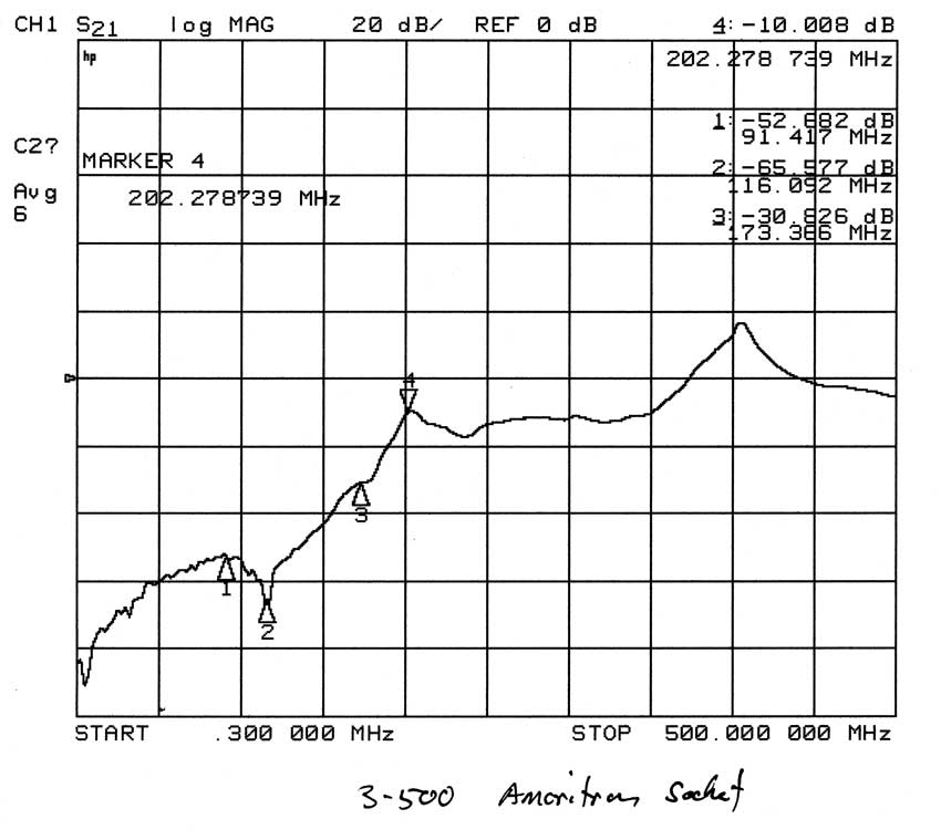
The lower the line the better the isolation and the better grounded the grid is.
Marker 2 at 116 MHz is the VHF peak in anode-cathode isolation. This is where the tube is most stable and least likely to oscillate. This socket has an exceptionally low grid inductance. Grid pins connect directly to a foil groundplane.
Marker 4 at 202 MHz is a minimum in isolation. Isolation is only 10 dB! This is the most common frequency range for a 3-500Z to oscillate at.
Note: The peak at 410 MHz is an artifact of the coupling system to the anode and cathode. 350 MHz is the highest usable frequency of the test fixture.
Look at the exceptional HF isolation of a 3-500Z with this socket. Feedthrough is in the order of -80db to -90dB. This is why a 3-500Z does not need neutralized.
In contrast, here is the 811A tube:
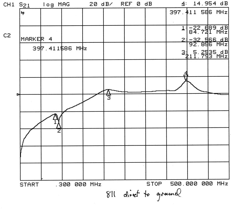
The 811A, even with a directly grounded grid, has only -22 dB isolation from input to output at 84 MHz. A single tube is open for oscillation at any frequency above 50 MHz.
Isolation below 30 MHz is only -40dB for a single tube. As tubes are parallel isolation decreases. This is why four parallel tubes need neutralized at HF.
The loss going less than zero dB is caused by impedance transformation (transmission line effect) in the test fixture and tube. The peak at 4 is from the same effect noticed in the 3-500Z trace. The peak at marker 4 is a test fixture artifact.
572B's have very similar isolation.
The following is a 3-500Z socket and tube in a Heathkit SB-220 amplifier. Note the change in HF isolation caused by floating the grids. Nothing gets better in the 3-500Z when the grids are grounded through capacitors. As a matter of fact everything gets much worse!
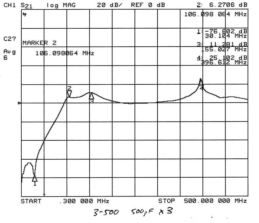
The cure for HF instability is to remove intentional undesired feedback. Ground the grids directly. If you have a particularly poor tube design, you will have to neutralize the PA!