Terminated loops have only recently become popular in Amateur radio, even though such systems were available commercially in the 1960's and earlier.
Elongated and Terminated Loops
In the early 1970's, the late W1BB, Stew Perry, forwarded an advertisement brochure for commercial loop arrays. The brochure described various arrays of receiving loop antennas. The antennas were manufactured and marketed by a Canadian manufacturer for commercial and military use. The brochure had pictures of diamond-shaped terminated loops, individual small loops, and loop arrays that looked like a number of Flag antennas strung end-to-end where each rectangular "loop cell" fed the next loop. The brochure gave array directional patterns over wide frequency ranges. Most patterns looked much better than patterns of other popular receiving antennas, such as Beverage antennas. The least expensive array's price, as I recall, was around ten thousand dollars! That early brochure started me thinking in terms of antennas other than Beverages.
Other things influenced me also, including a few antenna lectures by John (Jack) Kuecken and his book, "Antennas and Transmission lines".
Although detailed technical information was withheld, and even though this was before NEC modeling programs, it wasn't difficult to work out an acceptable electrical design for each array. I experimented with small loop antennas that would form each element or cell in a phased array, and eventually installed an array of eight in-line loop cells. That system allowed me to work Japan and other Asian countries through interference from multiple multi-KW LORAN transmitters. I was actually the first station in the eastern part of the USA to work Japan after WWII.
As the system was refined, I could work JA's on a regular basis. This was long before the broad LORAN pulse transmitters were removed from 1900 kHz, when the JA's transmitted between 1907.5 and 1912.5 kHz. (ZL's were also confined to LORAN frequencies, as were west coast stations.) Working DX through LORAN pulses was possible only because of the clean pattern and wide deep nulls of loop arrays.
Are they quiet because they are loops? Not at all!
One of the most damaging rumors to good antenna science are claims loop antennas have a mystical property that somehow rejects noise. Nothing is further from the truth, with one exception. Corona.
Any sharp point extended from the area of any structure, even from tall wooden ship's masts on old sailing vessels, is subject to corona in inclement weather. Sailors feared St. Elmo's Fire long before anyone knew what electricity was, and amateurs are burdened with it today when trying to receive in harsh or threatening weather. We often just don't know what causes the noise, and we can't see the fire in brighter skies, so we acknowledge this phenomena as "precipitation static".
The sharp point in a dipole, where the wire or tubing ends, not only promotes corona by virtue of the fact it is "out in space by itself", the open ends almost always have the disadvantage of being at a very high impedance point. The tiny random charge movements, with little current and very high voltage (high impedance source), inherent in conductors around the corona discharge, are driving a high impedance part of the system. This is an ideal situation to maximize transfer of tiny amounts of noise power into the receiving system. A dipole element is not only more subject to corona from sharp ends, corona is also impedance matched to the receiver system.
Loops do not have sharp points sticking out into air at high impedance points, and that can be an advantage in antennas exposed to high electric fields in storms or inclement weather. This is almost certainly where the rumor loops "reject" noise comes from. We overlook the fact corona noise is a function of the high impedance in the area where the antenna is sharply shaped. We fixate on the fact it is a "quiet loop" because of electromagnetic radiation voodoo, where the time-varying electric field is somehow independent of the magnetic field in a radio wave. A second effect occurs in full wave loops or very small loops, where the antenna has higher common mode impedance than a dipole, which can reduce common mode currents.
Are terminated loops actually loops?
Terminated loops do not behave like conventional small loop antennas. Terminated loops do not carry uniform in-phase currents over the entire antenna perimeter. They don't behave like directional couplers either. Small terminated elongated loops are antennas...not nearfield coupling devices coupled to other conductors (we hope).
Terminated loops are really just short verticals, with a phasing system inherent in the longer horizontal component of antenna wires. The loop's vertical areas receive the desired signals, while the horizontal conductors merely serve to act as transmission/phasing lines for the vertical (or sloping vertical) ends. A small elongated terminated loop acts like a simple two-element vertical array. Elongated terminated loops, and arrays of elongated terminated loops, are a special form of short phased verticals where phasing and feed systems are an integral part of the antenna. These antennas "want to" be verticals because the earth below them and somewhat closer spacing prevents the horizontal components from being efficiently coupled to space while the earth simultaneously enhanced the vertical radiation component of the gradually sloped conductors making up the antenna. The horizontal sections act as a wide-spaced air dielectric transmission line. This integrated system of elements, feed system, and phasing solves construction problems associated with arrays using more recognizable vertical elements.
This is true even in the K9AY Loop and Pennant antennas, which have sloped conductors. The sloped conductor behaves as a vertical (think about this when people follow the mistaken advice that sloping the last few feet of a Beverage "stops noise pickup of vertically polarized signals"), ten feet of vertical drop is still ten feet of vertical conductor exposed to vertically polarized signals. The fact sloped wire antennas work so well as verticals is testimony to how sensitive a sloped wire is to vertical polarization. If sloped wires weren't sensitive to vertical signals, the Pennant and K9AY Loop wouldn't work!
With any system there are tradeoffs, elongated loop antennas only allow very limited control of phase and unwanted high-angle response. We can't obtain optimum patterns (although a properly placed series capacitance will help) because the integrated phasing and feed system allows very limited control of current distribution and phase shift.
These antennas work best when propagation time of signals along the horizontal wires matches propagation time of the wave in space around the antenna, and when the earth or a ground system below the antenna is good. Suppression of high-angle horizontally polarized radiation, and maintaining velocity of propagation near unity, are why EWE antennas (and other forms of this family of antennas) thrive on good ground systems or good earth below the antenna. The desired earth effects are opposite those desired with Beverage antennas, an ideal situation for highly conductive soil!
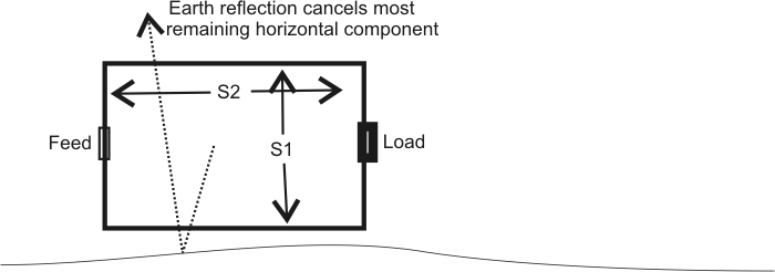
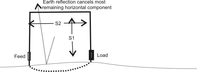
For best performance:
S1 is smaller than S2
S2 is as large as possible, but smaller than 1/4λ
Currents are equal at all points
Phase is approximately 180 - S2 between feed and load
The antenna is the equivalent of two small crossfire verticals, with horizontal component of wires forming a transmission line (radiation cancelled by earth) and vertical component of wires forming antennas (which are supported by earth reflections). A loop like this fires toward the feedpoint, away from termination.
Eznec file courtesy of Roy Lewallen. K9AY_Lewallen
| Wire | Segment | Magnitude (A.) | Phase (Deg.) |
| 1 feedpoint | 2 | 1.0069 | -1.27 |
| 1 | 4 | 1.0217 | -3.88 |
| 6 | 1.0356 | -6.23 | |
| 8 | 1.0486 | -8.38 | |
| 2 (at wire 1) | 2 | 1.0679 | -11.55 |
| 4 | 1.0809 | -13.68 | |
| 6 | 1.093 | -15.72 | |
| 8 | 1.1043 | -17.68 | |
| 10 | 1.1144 | -19.58 | |
| 12 | 1.1234 | -21.40 | |
| 3 (at wire 2) | 2 | 1.1347 | -24.06 |
| 4 | 1.1408 | -25.83 | |
| 6 | 1.1459 | -27.61 | |
| 8 | 1.1499 | -29.40 | |
| 10 | 1.1529 | -31.22 | |
| 12 | 1.1549 | -33.07 | |
| 4 (at wire 3) | 2 | 1.1561 | -35.72 |
| 4 | 1.1558 | -37.47 | |
| 6 | 1.1546 | -39.33 | |
| 4 (at load) | 8 | 1.1526 | -41.34 |
Looking at outer points highlighted above, we find a phase difference of about 22 degrees. Since one wire is fed from the top, and the other from the bottom (they run in a circle), there is also 180 degrees phase inversion. This is cross-fire phasing. The resulting phase is 180+ -22 = 158 degrees phase shift with the junction of 1 and 2 lagging phase from the junction of 3 and 4. This lagging phase causes the unidirectional pattern, firing in the direction of 1 and 2.
This K9AY is about 30-feet long, and about 25-feet high to the apex, but the effective height is a bit lower. This is because wires 2 and 3, being folded back on themselves at the apex, carry 180-degree out-of-phase currents.
160 meters is about 1.5 feet per electrical degree, so the array is about 20 electrical degrees spacing between front and rear elements. Ideal phasing would be about 22 degrees from 180, which closely matches what the horizontal component of wires adds! On 80 meters, the array is around 40 degrees long. In this case phase shift prior to counting the 180-degree inversion should be 40-degrees, which it is!
Pattern on 160 is:
Two short sloped verticals, at the same effective spacing, height, and phasing, show:
The K9AY behaves just like two short sloped verticals with the same phase shift.
The EWE
While outwardly appearing different, the Ewe operating mechanism is no different than a Flag, Pennant, or K9AY. It behaves as two small crossfire verticals. Instead of a wire return to complete a transmission line path, the EWE relies on earth. As such, it requires a good soil path, or help from grounded conductors.
| Wire | Segment | Magnitude (A.) | Phase (Deg.) |
| 1 feedpoint | 2 | .99947 | -1.51 |
| 4 | .99899 | -4.56 | |
| 6 | .99886 | -7.37 | |
| 1 (at top wire 2) | 8 | .99881 | -10.06 |
| 2 (at wire 1) | 2 | .99839 | -16.21 |
| 4 | .99794 | -20.10 | |
| 6 | .99735 | -23.99 | |
| 8 | .99662 | -27.89 | |
| 3 (at wire 2) | 2 | .99503 | -34.68 |
| 4 | .99433 | -37.34 | |
| 6 | .99368 | -40.09 | |
| Termination | 8 | .99324 | -42.99 |
Again we have crossfire phasing. One vertical is fed from the top end, and the other at the bottom. The phase difference is about 30 degrees or so, making the feed end lag the termination end by 180+ -30 = 150 degrees. Again, because of crossed feed and electrical distance of S2, we have proper phasing for the vertical ends. The feedpoint, because of the phase flip associated with the current path, lags the termination end. All close spaced end-fire arrays fire toward lagging current elements.
Flags, Pennants, and Ewes all behave in a similar fashion, because they all work on the same principle. There is no magical to them, and they are easily analyzed. They are all effectively phased verticals with acceptable, although less than perfect, phasing systems. While we might stumble on a shape that works by modeling or experimenting, we could also create a new shape just by following the guidelines of creating properly connected hidden feed lines. However they appear by eye, they do not function as loops. They do not carry uniform in-phase currents over the perimeter.
Why use terminated elongated loops?
It is easy to understand why "loop" systems, even very small loop systems, have become popular. Arrays of terminated loops vertical elements produce effective low-angle receiving performance along with a somewhat clean pattern. EWE's, Flags, Pennants, and K9AY loops are effective methods of building two-element broadband vertical arrays. They are easy, small, and inexpensive, even if noticeably less directive than two optimally phased driven verticals.
They cannot be fully optimized because horizontal components are not totally cancelled by ground effects and the opposing wire, and because we cannot vary phase and current level independently (electromagnetic radiation comes from current, not voltage). The inherent limitation of a "leaky" radiating phasing section that cannot be adjusted for phase and level independently distorts pattern a bit from ideal.
On the positive side, elongated loops are easier to construct than phased verticals. Phased verticals require more complex loading systems, grounds, and interconnecting coaxial cable feed systems. We have the standard old antenna tradeoff we just can't seem to get away from. We always must balance complexity and cost against performance.
Many people are working with various arrays of elongated loop antennas, so there are few contributions I can make other than describing how or why they work. I would like to suggest it is possible to extend the arrays end-to-end for some distance without external feed systems, and well-placed reactances can be used to modify patterns. Very little amateur radio work, other than my systems in the 1970's and 80's, has been done in that area. I'd suggest experimenting with series capacitors, perhaps placed mid-way in phasing (the horizontal wires) areas, can increase velocity of propagation through elongated loop arrays and increase directivity. But it all remains a compromise of phase and current distribution, and minimizing "leakage" from the required horizontally distributed physical component in wires, when feed systems are integrated into structure.
Are small loops hyper-sensitive to vertical masts?
There is no compelling evidence that any of these antennas are more sensitive to vertical metal masts than any other antenna would be. As a matter of fact, the only basis for such claims appears to come from models that fail to pass simple recommended tests for model accuracy and stability. If we build a model that is flawed and oversensitive to changes in things, like the number of segments used in the model, we can expect it to be hypersensitive to nearly any wire change!
Other than keeping a short mast a few feet away from vertical wires and NOT connecting that mast directly to the antenna or feed line, I wouldn't hesitate for a second using metal supports. My large arrays of loops in the early 70's used metal masts, my arrays in the 80's did, and as have commercial arrays.
Feedpoint Matching
Great care must be taken in decoupling the feed line from the antenna in the balanced versions of these antennas, although the EWE (being unbalanced) is relatively immune to such problems. Keep in mind the antenna generally looks capacitive as a common-mode structure, so inductive decoupling (i.e. a choke coil of coax) can actually increase system problems. The best common-mode isolation system would be an isolated winding transformer designed with minimal capacitance between the antenna winding and the rest of the system. I use a small transformer with stacked 73 material binocular cores in feeding some of my high impedance "log-Beverage" arrays, and similar transformers should work with ~1000 ohm impedance elongated loop antennas.
Because this transformer only has a single turn primary (two turns with the balancing pass), I'm able to reduce stray capacitance to a dozen pF or less. It has excellent balance, low SWR over a wide bandwidth, and very low loss. The reasonably low transformer capacitance, when used in concert with proper feed line grounding and routing, should make the system relatively immune to common mode problems. I'd route the feed line horizontally directly away from the end of the antenna for a few dozen feet (but never a distance approaching 1/10th wavelength or longer), and then drop the feed line to ground earthing the feed line shield at that point. Decoupling beads or sleeves belong on the receiver side of the shield grounding point, not between the ground and the antenna!
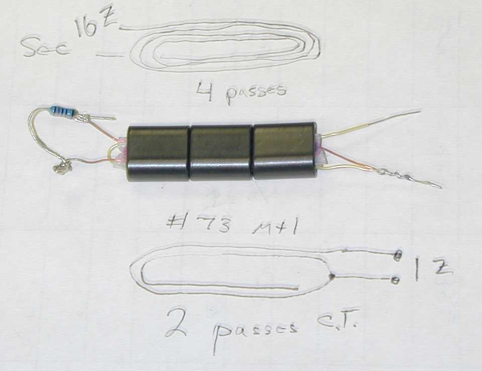
I wind this transformer on three Fair Rite Products 2873000202 cores (about 1/2 inch square and 1/3 inch thick 73 material). The high impedance (secondary) winding is #26 enameled wire through Teflon tubing, while the primary is Teflon coated wire-wrap wire wound outside the tubing. The small extra pass that "dangles" on the low-Z primary winding helps balance the system, even though it adds a few pF of capacitance.
By the way, a Faraday shield will only make things worse. It will increase unwanted stray capacitance and might deteriorate the high impedance winding's balance if the shield is not properly grounded. The proper grounding point for a Faraday shielded primary is opposite the exit point of the primary winding, or on the secondary winding's exit side of the transformer. Most Faraday shields described for Beverage and other transformers are not only useless, they are often incorrectly grounded and actually increase unwanted coupling!
©2003 W8JI