Related Pages
The following is a description of a few basic safe metering systems. These systems are designed to be safe for the equipment and safe for the operator. See page on power supply design.
Block Diagram
This is a block diagram of a typical metering circuit. The tube's control grid to grid-meter path is normally through the chassis. This lets the control grid be directly grounded to the chassis. In the event of a tube arc, grounding the grid directly is safer for everything.
Note that ALL plate current must flow through the plate meter, and all grid current must flow through the grid meter. Provided something is not either accidentally or intentionally improperly wired, bias voltage or bias system will not affect meter accuracy.
Equivalent Circuit For Amplifiers
Most high voltage power supplies, to allow high voltage current measurements (plate current) without having dangerously high voltages on the meter, and to also allow grid current measurements in grounded grid amplifiers, are constructed with the negative power supply lead floating from chassis ground.
The typical current metering circuits for plate and grid, used in a floating-negative-rail power supplies, is shown here. The entire high voltage power supply section, which includes all rectifiers, bleeder resistors, and filter capacitors is fully contained inside block PS1. The power supply block (PS1) negative rail floats from ground, allowing metering of negative supply rail current and (if required) grid current. The meter shunts, or current meters, are inserted in the negative lead path to tube cathode and chassis. This keeps the metering system near ground potential when under normal operating conditions.
Floating the negative supply lead for metering, while not nearly as hazardous as inserting meters in the HV positive lead, is not entirely worry-free. If the positive HV terminal shorts to ground, perhaps from a tube arc, wiring, or component failure, the negative rail will try to rise negative to full supply voltage. Because of this, a negative rail voltage-limiting clamp should be added. The clamp should be something that fails safe, presenting a low resistance to chassis ground. (The ARRL Handbook and many other sources use a high-wattage 10 or 20 ohm resistor, but such methods are not safe. A negative rail safety resistor is not a good idea for a few reasons, as we will see in the text below. The clamp should be a hard clamp, like a semiconductor diode.)
Grid current path
The blue dashed line shows the grid current path. Voltage drop across R3 includes only grid current, or any current from chassis up to the negative HV supply rail. The grid current path does NOT include any power supply or anode current.
When the grid meter system is properly wired, grid or cathode bias voltages will not cause an error in grid current reading.
Plate current path
The entire plate current path is this red loop. R2 fully samples plate current and nothing else. Bias voltage or circuitry cannot cause false readings of plate or anode current.
Cathode bias voltage does subtract from anode voltage, but normally bias is less than 0.5% of high voltage, so any errors are negligible.
In a grounded grid amplifier, drive voltage adds to high voltage. This actually increases the effective high voltage beyond what HV metering indicates. While some articles tell us driver power is not measured and feeds through, that is not factual. The additional current supplied by the drive power is fully accounted for, only the additional voltage is not measured.
The cathode shares the anode and grid paths. Any meter or shunt inserted in the cathode will indicate cathode current, which is a combination of anode and grid currents. Similarly, bias diode D1 sees the full cathode current, which is the sum of grid and anode currents. The value of D1 will not affect current reading accuracy, D1only affects the cathode to ground voltage (bias). The bias system (D1) must be isolated from chassis and power supply negative.
Grounded Grid Amplifier Metering with Grid Meter
We really should have a dedicated grid current meter in every medium power or high power amplifier. The single most important meter in a grounded grid amplifier, other than an accurate peak-reading power output meter, is the grid meter. If we watch any single current or voltage in the amplifier to tell us how an amplifier is driven, tuned, and loaded, the grid meter is by far the most important thing to watch!! Grid current tells us when the plate circuit is resonant, when the loading control is properly adjusted, and when the amplifier has lost plate voltage or the load. Grid current tells us when an amplifier is being overdriven, and when tank voltages are excessive.
Grid current will also tell us if an amplifier is oscillating. If we watch grid current with the amplifier "keyed" and no drive power, and if grid current varies with setting of the plate tuning capacitor, a parasitic oscillation is likely.
The plate current meter (in conjunction with a HV meter) only tells us plate input power. Plate current does not obviously indicate improper loading control settings, or if the amp is being overdriven. The plate current meter generally won't tell us if the amp is oscillating, give us any idea about linearity, or indicate excessive or the potential for excessive tank voltages.
Let's look at a typical circuit for a grounded grid amplifier external power supply.
Note D2 and C2. Both are critical safety components. When properly sized D2 and C2 will protect the meters, both meter shunts, and the operator under any condition of HV fault.
D2 threshold voltage must exceed the larger voltage of meter full scale R1 or R2 voltage.
Voltages in R2 and R1 subtract, so far as D2 is concerned. If grid meter voltage drop is 1 volt, and if plate meter voltage drop is .5 volts, D2's conduction threshold (breakdown voltage) must exceed 1 volt (the higher of the two) by a reasonable margin. This would require two silicon power rectifiers connected in series (~1.3 volts conduction threshold).
C2 Selection Considerations
This is one of the rare cases where too much headroom is bad. Use the lowest voltage C2 available in a small disc capacitor, but try to select a component with reasonable physical size. I typically use 50 volts for C2. The value generally is around .05 to 0.1 µF. This capacitor serves multiple functions. C2 bypasses D2 for RF and very short transients. C2 also provides an additional clamp at 100 volts or so if D2 should ever open. This clamping action, as an additional failsafe to hold the negative rail to the chassis, is why C2 should be a low voltage but reasonable physical size component.
D2 Selection Considerations
D2 can be any diode that can survive maximum fault current (HV over R4 plus worse-case path fault resistance) without destroying the case and blowing the diode path open. Fault path resistance would generally be the sum of filter capacitor ESR and R4's physical resistance.
R4 typically should be chosen to limit fault current to non-destructive values. Typically, in small amplifiers (below 5 kilowatts output), R4 should be about 5 ohms for every 1000 volts. A 4,000 volt supply would typically require around 20 ohms fault path resistance. Typically that path resistance would be comprised of 2.5 ohms ESR in the capacitor bank and 2.5 ohms total in wiring, RF chokes, and other resistors. In this case R4 would be 15 ohms, which adds to the other wiring and component resistances for a total fault path resistance of 20 ohms.
With 4000 volts the system would have 4000/20 = 200 amperes fault current. A 1N4007 would only handle 30 amperes before becoming unreliable and shorting, but that does not mean it would burn open. We really have to test diodes to see how much pulse current blows the case open. Better quality 1N4007's will handle 100 amperes for 30-50 milliseconds, and 1N5408's over 200 amperes for the same time period. If you are unsure, use a 1N540X series diode, like a 1N5408.
D2 may require more than one diode in series. If the grid or plate shunt resistance drops more than 0.5 volts at maximum current, additional diodes are connected in series to form D2. It is best to consider each silicon power rectifier diode about 0.5 volts per diode.
Shunts and Multipliers calculating or selecting metering resistance values
In the 1980's, I managed a precision D'Arsonval meter manufacturing group at a major meter and aftermarket automotive meter supplier. This provided a valuable lesson in meter calibration and manufacturing.
- For best current measurement accuracy using external meter shunts, meters should be calibrated with voltage
This is because a meter across a shunt actually measures the voltage drop across the shunt. This is why we see things like "30mV 10A shunt" in precision shunts
- For best voltage measurement accuracy, meters using external multipliers should be calibrated with current
This is because meters used with multipliers to measure voltage really are measuring current through a multiplier resistance
There are two resistances important to current metering, the meter series resistance and the shunting resistance. These two resistances control the current division, and along with the meter FS current, determine the meter scaling. The meter series resistance and current determine the meter full scale voltage, and that full scale voltage reads across the shunt. By adding external resistance we can find combinations that allow use of standard resistor values. Resistor values are available in many standard sizes, but certain values are more commonly available. Normally resistors have prefix numbers like 10, 12, 15, 18, 22, 27, 33, 39, 47, 56, 68, 82, and starting over at 100, that are multiplied by a decade multiplier.
To make things easy, I use Excel spreadsheet for picking resistances
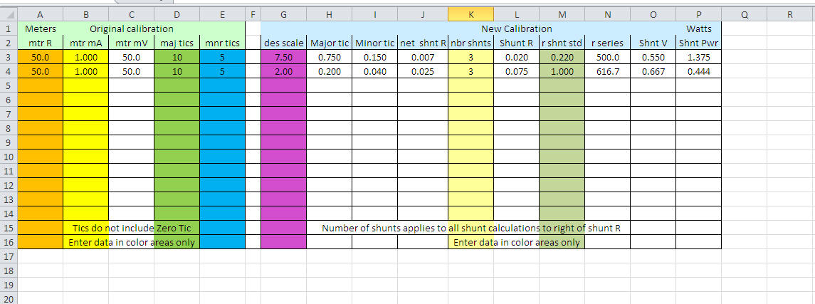
You can download it here:
Spreadsheets/meter calculator.xlsx
Meters in amplifiers or transmitters are the same. Plate or grid current meters almost always read voltage developed across a shunt resistance, while high voltage is measured by measuring current flowing though a series-connected multiplier resistance.
In
the circuit to the left, shunt resistor R1 sets the voltage applied to the meter
for a given current.
R5 is sometimes necessary to dial the meter in when meter voltage sensitivity does not lend itself to a common off-the- shelf value for shunt R1.
By selecting the proper combination of R5 and R1, we can use almost any meter to accurately measure power supply DC output current flowing through PA tube anodes. This applies to transmitters and all other systems, not just external amplifiers.
The same idea applies to grid current shunt R2 and meter multiplier R6. By selecting the proper multiplier resistance for R6, and the proper current-shunt for R2, we can almost always find standard values. The R2/R6 combination is for measuring grid current (shown above for typical grounded grid amplifiers).
Picking The Correct Resistance Values
Here's how to determine resistors for full-scale current:
What is the FS voltage of the meter?
Full-scale meter voltage sensitivity, important in any current meter used with an external shunt, is meter current times meter resistance. If the meter is 1 mA and has 50 ohms resistance, full-scale sensitivity is .001 amperes*50 ohms = .050 volts, or 50 millivolts FS. 50 millivolts is a very common meter movement value.
Another case might be a meter like Ameritron uses in the AL80A. The AL80A used a 1 mA 450-ohm meter. Full scale sensitivity is thus .001 * 450 = .45 volts, or 450 mV. This was not a common meter movement; when we manufactured the meter a 200-ohm resistor replaced each wire meter lead inside the meter. This allowed use of a standard 1mA 50mV movement. For home builders the resistors could be placed outside the meter housing, but at Prime Instruments we placed multipliers inside the meter housings.
I generally do not like to use 50 mV meters, or other very sensitive meters, directly with shunts unless there is no other choice. 50 mV meters, or low voltage sensitivity meters, are more sensitive to ground loop and wiring errors, and they are more prone to catastrophic damage if a shunt opens. Consequentially, I almost always use a multiplier resistance combined into current measurement systems using shunts. A case where a multiplier could not be used would be a high current shunt in a low voltage supply. We would not want a 200 mV shunt in a 5 volt supply line, because it would reduce voltage to 4.8 volts. We also would not want a high voltage drop with high current, because of shunt heating. A 200 mV shunt with 20 amps would dissipate .2*20 = 4 watts.
What do we want to measure?
Let's work through a few problems.
We need to pick a current-shunt that matches the meter's FS (full scale) voltage. We also must remember a portion of shunt current flows through the meter.
The correct formula for the shunt is meter voltage-sensitivity divided by desired current minus meter current. Where E = meter sensitivity in volts, I=current being measured, and i=meter FS current, we have: E / I - i = shunt resistance
Let's say we want 750 mA full scale and a standard 50 mV 1 mA meter. We want 750-1 = 749 mA through the shunt to produce 50 mV across the shunt. The "missing" 1 mA from the shunt flows through the meter, for a total of 750 mA. The shunt resistance is .05 divided by .749 = .0668 ohms. That's a problem for a few reasons:
- First, people cannot go out and buy .0668 ohm resistors from inventory, they would be custom manufactured
- Second, tiny resistances in foil traces, wires, or solder joints can be a large percentage of .06 ohms, and significantly change the effective shunt resistance
- Third, any ground loop voltages or switch contact imperfections can upset the 50 mV meter voltage. 50 mV is not very much voltage
- Fourth, if the shunt opens, we don't have much current limiting in the meter
What can we do to make things less critical? We can increase meter voltage!
What if we made the meter 450 mV by making total meter resistance 450 ohms?
Adding R5, a multiplier of 400-ohms, in series with a 50-ohm meter solves the problem. Meter current sensitivity is still 1 mA, but meter resistance increased from 50 to 450 ohms. Now meter FS (full scale) sensitivity is 450 mV (.45 volts).
In this case, with the meter resistance increased by a multiplier, the meter shunt must develop .45 volts. The shunt becomes .45 volts divided by .749 amperes = .6 ohms. This is a standard precision resistance. This is why Ameritron used a 450-ohm, 1 mA, 450 mV meter. Ameritron could purchase standard .6-ohm shunts, rather than special custom wound shunts, and save time and money. Additionally, customers could find standard replacement resistors from many suppliers.
Grid current, or any other current, is handled in a similar manner. To read 400 mA grid current with a 1.5 ohm shunt, the meter must have a sensitivity of 1.5*.4 = .6 or 600 millivolts.
Conversely if we have a 450-millivolt meter, the shunt would be .45/.400 = 1.125 ohms. Closest standard values are 1 or 1.2 ohms. This is the beauty of using R5 or R6. We can use almost any shunt handy, just by adjusting R5! If we use a very common 1.5 ohm resistor, we would have 1.5 ohms *.4 amps = .6 volts. By using 600-millivolts FS, a standard shunt resistor of 1.5 ohms, along with a suitable R6 multiplier of 150 ohms in series with a 450-ohm 1 mA meter, still reads 400 mA.
The AL1500 uses a single 1.5 ohm grid resistor. To read full scale 200 mA, the AL1500 grid meter is .2 * 1.5 = 300 mV full scale. This allows the op-amp that limits grid current to be set to trigger around 225 mV or so, taking the amp off-line with 150 mA grid current. The AL1200 has a 400 mA grid meter, so it uses two 1.5 ohms in parallel for .75 ohms. Once again FS voltage is 300 mV, the same movement is used for both amps, but the scale is changed and one extra 1.5 ohm resistor is paralleled in the AL1200.
Shunt dissipation is FS (full scale) shunt millivolts times measured FS current. With a 400mA FS meter and 300 mV, the shunt dissipation is .12 watts total. Overkill that dissipation when selecting the part to ensure reliability and stability.
Meters in Old Tube Transmitters
Meters in old transmitters generally read grid current and grid voltage of the PA stage. This always involves switching both meter leads.
Let's look at a sample transmitter circuit from a Heathkit transmitter:
Notice both leads of the meter float, and the meter is a 1 mA 47 ohm meter.
This is a .001 A * 47 ohm = .047 V or 47 millivolt movement. Most likely it is actually a standard 50 mV movement, and there was a simple tolerance error in manufacturer measurements. Perhaps they measured the meter in circuit.
For the purpose of this discussion, the numbers will be taken literally.
This meter is then two things:
For voltage measurements in the transmitter, the meter is a CURRENT meter. As long as the measured voltage is more than ~100 times the millivolt FS sensitivity of the meter, we can just consider it a pure current meter for voltage measurement functions.
For current measurements in the transmitter, the meter is a VOLTAGE meter. As long as the measured current is more than ~100 times the FS current sensitivity of the meter, we can just consider the meter a pure voltage meter for current measurement functions.
This is the grid current function. The 5.55 ohm shunt resistor at B and C is in the grid path. The grid becomes more negative than the grid bias supply, and forces current through the shunt back into the bias supply.
5.55 ohms will develop 5.55*.001 = .00555 volts, or 5.55 millivolts, per milliampere of grid current through the resistor.
With 47 mV full scale and no meter current, this will be around 47/5.55 = 8.46 mA full scale. We have to be careful, because 8.46 mA is close to the 1 mA meter current. We can just add the meter current back in, so current is 9.46 mA full scale.
The meter is 47 ohms, the shunt is 5.55 ohms. This actually makes true shunt resistance 4.96 ohms. That's 4.96 * .001 = .005 volts or about 5 millivolts per milliampere. 47/5 = 9.4 milliamperes full scale.
Why is is calibrated at 10 mA full scale? Because Heathkit used a low meter voltage (low meter resistance). Switch and wire resistances will make the meter read lower, and it probably is about 10 mA full scale!
A higher resistance meter would have reduced the effects of hidden switch contact and wiring resistance, which would make metering more repeatable and accurate. Although Heathkit did not do that, this is why we should really use a multiplier resistor on the meter or a higher resistance meter, if possible.
Tube Transmitter Plate Current
This transmitter used a safe plate current system. Like most amplifiers, they floated the negative rail of the power supply.
The .1 ohm resistor by D (lower left corner) is the plate current meter.
Plate current is measured between the chassis and center tap of the plate transformer, with the filter caps and bleeders floated back to the center tap.
Modulator cathode current, that includes plate and grid current from all four modulator grids, is through the .1 shunt at F and G.
The sensitivity across .1 ohms is .1*.001 = .0001 volts or .1 mV per milliampere.
With a 47 mV meter, we have 47/.1 = 470 mA full scale. We can see how unimportant meter current now is, because who cares if we are 1 mA off from 470?
We also can see, 47 ohms must not be the true meter resistance. Most likely, as mentioned at the start, this is a standard 50 mV meter system when switch and wiring resistances are all accounted for.
I hope this helps people learn how to use any meter they have with minimal fuss and bother. Now you see why meter manufacturers, at least internally, work with millivolts and current for all meters, and why commercial shunts are defined as mV per ampere. When a meter reads voltage with an external multiplier, it is normally worked with and calibrated using current. When a meter reads current with and external shunt, it is normally worked with and calibrated by using voltage.
Again shunt heat is FS (full scale) meter voltage times maximum scale current, or I^2*R through the shunt resistor.
Adapting a Junk Box Meter
A recent e-Ham thread had a person replacing a 200 ohm, 10 mA Johnson Navigator meter with a higher quality D'Arsonval meter. This resulted in a pinning meter, it was out of calibration even though he used a 10 mA meter.
The problem was the new meter had a FS sensitivity of someplace around 30 mV sensitivity. He measured 3 ohms across the meter terminal (out of circuit) , so it was around 3*.01 = 30 mV FS.
The Johnson had a 10-ohm meter shunt, and had a 10 mA meter that was scaled to read 200 mA full scale. This means the shunt developed .2*10 = 2 volts to drive the original meter. To be perfectly accurate we should deduct the 10 mA from the shunt current, so the actual meter shunt voltage was .19*10 = 190 mV with a 10 mA meter. He needed a 190 mV FS meter at 10 mA.
The most simple solution was to add a ~200 ohms in series with his 10 mA meter. He had a 180 resistor handy. This gave 183 ohms or so total, and made the meter 1.83 volts FS. This was close enough to the required ideal 190 ohms, about 5% error.
With just two resistors, and often just one resistor, any equal or more sensitive meter will generally work with existing shunts.
Metering Without Grid Meter
Since the grid meter is the single most important meter for properly tuning or operating a class AB2 or class C grounded grid amplifier, it really should always be included.
A generally proper system, but less grid meter, is shown below. The supply doesn't need to be this complex, but I included inrush limiting and critical safety components. In my opinion, it is better to spend an extra dollar and be safe by adding C2, D2. C2 and D2 protect the meter, and they protect the operator. It might also be wise to spend an extra $20 or so and have inrush limiting (RLY1, R7). R4 should always be included if you use oil filled capacitors. R4 protects the tubes in the event of an arc. Unless you included enough resistance in the RF deck plate choke and in the filter capacitors, R4 is required to protect PA tubes!!
Filter caps are isolated from chassis ground
Current for bleeders is in a closed path across the bridge rectifier
Filtered DC output from the negative capacitor and rectifier terminal goes through the meter shunt
Meter Wiring and Layout
Wiring meters to shunts can be critical. Most external shunt current meters operate between 50 mV and 500 mV full scale. As a general rule higher currents demand lower the meter full scale voltage. Shunt dissipation is directly proportional to voltage drop across the shunt for a given current. Where a 500 mV 50 amp shunt would generate 25 watts of heat, and require a shunt stable with resistance over wide temperature ranges, a 50 mV 50 amp shunt dissipates only 2.5 watts.
Proper shunt connections require thought and common sense, and a feel for what the meter and shunt are doing. Here is a correct shunt wiring method:
A and B are shunt termination points. This is where the main current flows through the shunt.
M1 and M2 are the meter terminals. This is the rule even if one end of the shunt is grounded!!! In other words if we have a shunt going to ground, the ground connection would be at A or B. The meter would have two wires returning to M1 and M2, even if one meter terminal eventually goes to the chassis. NEVER depend on a chassis path, a shared foil path, or a shared wire path from a meter terminal to the grounded end of a grounded shunt.
Let's consider the large strip or bar shunt (?). If the meter was bolted across the shunt at terminals A and B, full load current would flow though the bolted terminals. If the bolts loosened or developed a high resistance, current readings would go up. If the shunt unbolted or lost connections (or even had a slight resistance in connections), the meter itself would burn out!! When we connect properly to M1 and M2, any bad connection simply causes the meter to read low or have no reading. There is nearly zero risk of damaging the meter, plus connection resistance doesn't change meter accuracy!
The same connection problem occurs inside an amplifier or transmitter, except the problem is exaggerated because the shunt is normally a two-wire standard resistor. With a standard shunt, none of the connections cause ground loops or excessively high readings. A properly wired meter floats across the shunt tap points; loose shunt connections never cause a high reading or damage the shunt.
In an amplifier or transmitter, wiring can have multiple problems. If the meter is grounded to the chassis, or to some other ground point independent of the shunt, a loose screw, broken wire, or cold joint could throw readings way off. Many connection failures take the shunt out-of-circuit while the meter remains connected. This can cause a high reading, or destroy the meter.
Nearly all meter failures from overload, or oddly behaving meters, are caused by equipment wiring or design errors.
In the resistor shunt shown above, meter leads must be returned to the shunt connection pads at M1 and M2.
Capture of circuit layout area for shunt resistor.
The meter is connected across the resistor, not to the current-path traces to the resistor. Foil trace resistance cannot affect shunt resistance.
Notice both meter leads float.
Circuits to the left show proper and improper meter wiring techniques. Electrically they appear identical in function, but the lower circuit has needless safety, reliability, and ground loop problems. Lack of one cheap diode puts the meters and operator at risk if HV faults to ground or a connection fails, and lack of one single additional wire from the meter to shunt allows voltage potential differences along the ground path to affect the meter. With a 50 mV meter, just one millivolt of ground loop bias can produce 2% error!
It doesn't matter if the meter and shunt are on the same chassis unit or not, so long as BOTH meter wires travel directly to the shunt. With proper wiring, the shunt can be located near the meter or remote from the meter on another chassis.
Be sure to RF and transient bypass the protect diode, a .1 uF 50-100 volt large disc capacitor is ideal. Remember to use more than one diode in series if shunt voltage is over 0.5 volts.
The protect diode must always be located at or very near the filter capacitor bank. It is permissible to have an extra clamp or protection diode near or in the RF deck, but the primary protection diode must always be located at the B- end of the filter capacitor stack.
Power Supply Design soon