 This window can tighten or expand in time, but the order has to
remain the same sequence.
This window can tighten or expand in time, but the order has to
remain the same sequence.
Related pages at
The text below covers electronic circuit to sequence and speed separate relays (like dual vacuum relays) and describes how to sequence mechanically ganged contacts like those in open frame relays.
This page deals with the actual amplifier relay transfer.
All energy available from the operating output device in an RF power amplifier has to go somewhere!
Amplifiers must have a load connected to the output anytime drive is applied to the input. Without a load, the amplifier can be damaged by arcing or excessive internal voltages or currents. If there is no antenna connected, the energy builds up in the tank circuit or other energy storage system in the amplifier until something absorbs the excess energy that would have made it to the antenna.
In cases of unstable amplifiers, such as those using non-neutralized tubes with high internal feed-through capacitance (i.e. 572B's or 811A's), the output relay must be closed before any idling current is applied. (See stability) To ensure safe operation, the amplifier has to be brought "on line" in a specific sequence in comparison to RF and bias.
The normal safe timeline of engagement (turn on) relay system sequencing is:
This entire sequence can take up to 15mS with large open-frame relays.
The release sequence must be:
The time sequence looks like this:
This window can tighten or expand in time, but the order has to
remain the same sequence.
If this process is not followed the relay, bandswitch, capacitors, or other tank components can be damaged from intermittent arcing!
Even though all radios should have a transmitter inhibit delay, many radio designs do not include such delays. The radio output delay primarily prevents shutting down of the radio during leading edges while relays transfer, and annoying broadband clicks or spits at the start of VOX closure or each transmitting cycle.
Some radios have incorporated delays, but incorrectly applied the delays. For example, some early Kenwood radios actually delayed the turn-on and turn-off of amplifier relays, forcing amplifiers to "hot-switch". Such radios are often disastrous to amplifier component life.
Relays can be made faster by operating them from a higher-than-normal supply voltage, and using external current limiting to provide a constant current at the relay's rating. For a single relay, omit everything associated with RL2. R3 becomes a jumper.
A two-relay circuit would look like this:
figure 1
R1 1k 1-watt
R2 1k 1/4-watt
R3 100-ohm 1/4-watt
R4 found by the following, where Irl1 is the antenna relay current:

For example:
Power rating of R4 is:
![]() where I is RL1 current and R
is R4 resistance.
where I is RL1 current and R
is R4 resistance.
C2 input time delay cap, normally 10-50uFd 10v
D1 1N4001-1N4007
D2 3-4V small zener (.25w-1w)
Q1,Q2 NPN power transistor. Vceo rating must exceed Vcc supply voltage, plus safety margin. Imax must exceed relay current ten times or more. Watch dissipation! Use hfe above 40 for best current stability.
Power Source:
R2 sets current through RL1 (antenna relay). The adjustment range of R2 is from zero current to a maximum where only RL1 resistance limits relay current. R2 must be adjusted for rated current through RL1.
R3 should be set for proper delay of RL2 (input relay).
D1 adds delay to release of RL1 (antenna relay). If release of antenna is too slow, add small value of series resistance until RL1 opens just after RL2 opens.
The above circuit has the following features:
Relay pull-in is always slowed by the inductance of the armature coils. Since RL1 is fed by a voltage higher than normal, current will reach pull-in strength much sooner than with normal supply voltages. Q1 is a constant current source, adjusted by R2. This circuit prevents RL1 from being overheated, or having excessive steady-state operating current. Q1 also limits the voltage appearing at Control_TX.
After RL1 (antenna relay) current reaches a value that allows contact transfer, Q2 will conduct. This applies current to RL2, the input relay. It pulls in last, time delay is set by R4, R3, and C2.
Upon release of Control_TX, RL2 releases with only internal relay delays. RL1 is held on by the current loop through D1 as the field tries to collapse. This causes RL1 to have a longer release time than RL2, so the antenna remains connected longer.
No back-pulse voltages make it to the exciter, because of the circuit configuration.
This is a simple, safe, adjustable relay system.
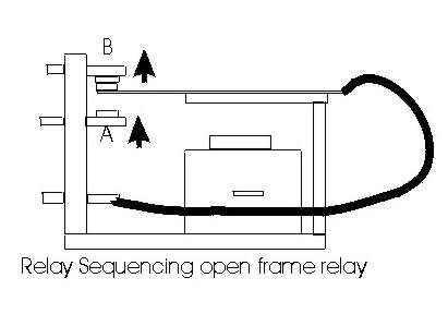
Large multiple-contact open-frame relays using a common armature can be mechanically sequenced by slightly bending each contact carrier, the associated normally open contact, or both.
By carefully pushing on the armature center:
1.) Reference the pictorial above, use needle nose pliers to bend the unused normally OPEN contact at the amplifier tank circuit connection UPWARDS. Do this by positioning one jaw on the top of the bakelite frame and the other under the outer tip of "A" and squeezing until "A" is just slightly bent upwards towards the moving contact. DO THIS ONLY ON THE OUTPUT CONTACT! This will force the TANK CIRCUIT of the amplifier to connect to the antenna BEFORE the input circuit connects. This change prevents arcs in tank components caused by improper relay timing.
2.) Locate the unused normally closed contact for bias switching. Using the same technique above, bend "B" (the normally closed contact) upwards until B no longer contacts the moving contact. This change puts 1/3 more contact pressure on the amplifier bypass contacts, and decreases receiver dropout when the amplifier is on bypass.
When properly modified, you should see the output contact make slightly before any other contact on the relay when the armature is manually closed. You should see the UNUSED bias or cathode switching normally closed contact have a slight gap when the relay is NOT energized.
Separate relays offer a unique problem. First, some relays can actually be dangerous to use.
|
NEVER USE REED RELAYS, UNLESS YOU ARE ABSOLUTELY SURE EACH RELAY HAS A SINGLE REED THAT MOVES BETWEEN THE NORMALLY OPEN AND CLOSED STATIONARY CONTACTS. MANY REED RELAYS HAVE A NO and NC REED IN A SINGLE COIL. THEY WILL RUIN EXPENSIVE RADIOS IF A REED WELDS SHUT! NEVER USE COMBINATIONS OF SINGLE THROW RELAYS TO MAKE A DOUBLE THROW RELAY!! DUAL REED RELAYS OR SEPARATE SINGLE-THROW RELAYS (like a SP NO and SP NC combined to make a SPDT section) CAN CAUSE SEVERE DAMAGE TO YOUR AMPLIFIER OR RADIO. |
Relays must have an absolutely fail-proof positive transfer between open and closed poles. The normally closed poles should also be series-connected so the path is through both normally-closed contacts. This will prevent any possibility of accidental connection between amplifier output and input in the event of a relay or component failure.