related external G5RV analysis
88 ft or 44 ft Dipole
Recently I've been fielding service problems from people using 88-foot long dipoles. I also see people recommending this antenna when there is limited antenna space, even when there is sufficient room for a normal dipole. The problems I hear of generally center around tuner damage, balun damage, or failure of a tuner to match the antenna. An analysis of various installations has shown that an 88-foot dipole is too short to be a reliable antenna on 80 meters (or a 44 foot dipole on 40 meters) without some form of low-loss reactance compensation at the antenna feedpoint or very near the antenna.
While pattern looks excellent on higher bands, lowest band performance of a short dipole (in this case 88 feet long on 80 meters or 44 feet long on 40) certainly leaves a great deal to be desired. feed line VSWR is over 100:1 with an 88 ft long dipole 30 feet high using typical ladder line feeders (400 ohm nominal impedance) on the bottom of 80 meters.
Looking at an 88 foot long dipole of #16 wire in EZnec 4:
EZnec4 predicts:
(I used 400 ohms in the model because most 450 ohm ladder line is really around 400 ohms.)
This means the balun and antenna tuner see an impedance somewhere between 3 ohms to 50k ohms depending on feed line length. This is in stark contrast to 22:1 maximum possible VSWR and 18 to 8800 ohms impedance range (depending on feed line length) when a dipole or doublet is full length!
Let's look at a Smith Chart of that antenna on 80 meters as feed line length is varied:
Minimum Z to tuner shown above.
Maximum Z to tuner shown above.
It isn't the efficiency of the antenna that is in question. The problem is feed line efficiency, balun requirements, and high VAR power levels in the tuner system. When balun, feed line and tuner losses are included, losses can be terrible. In many cases 80-meter efficiency of an 88 ft dipole, or 40-meter efficiency of a 44 ft dipole, can be 10% or less. Of course you can get lucky and make as high as 75% efficiency with a sweet length of feed line. The main point is system like this are very tough on components.
The text below actually applies to any short dipole. If you don't like the dB or so loss of a G5RV system (including tuner and feed line losses), you really won't like the performance of an antenna significantly shorter than a 102 ft long G5RV.
Loss in a Short Dipole
Power loss in short dipoles primarily comes from compensating reactances and matching to 50 ohms. This is because VAR (volt-amperes reactive) power is very high.
In a system with reactance, current and voltage are not in phase or in step. Because maximum current does not occur at the same time as maximum voltage, the simple product of current times voltage (I*E=P) can be much higher than the actual useful power. The higher reactive current causes increased current squared times resistance (I^2*R=P) heating and loss. The higher reactive voltage, in a similar fashion, causes increased dielectric losses.
In the worse case, power loss caused by increased voltage and current in reactive systems can actually cause component failure.
Short dipoles and verticals (like a 44-ft vertical) will almost always model with very good efficiency. The is because the losses associated with a short antenna have little to do with the antenna itself. Nearly all losses in very short antennas are in the feed line and matching system. Modeling programs have a perfect lossless feed and matching system unless they include the real mismatched feed line losses and matching system losses.
Let's look at an example by looking at the suggestion of shorting a dipole to approximately .33 wavelengths, or 44 feet, on 40 meters.
Dipole Impedance
The analysis in the following text is not a worse case analysis, but rather a typical best case analysis. In the real world VSWR could exceed 100:1 when the antenna is closer to earth if losses are low or modest.
The Eznec 40 meter model of a 44 ft dipole is shown here:
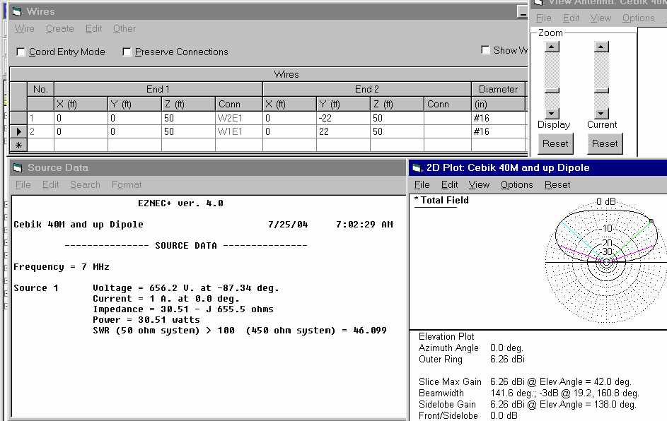
From this we see the feedpoint impedance is 30 ohms resistive, which we should all agree is not too bad. The problem is the feedpoint reactance of -j655 ohms. This reactance results in a VSWR of over 48:1 on a typical "window ladder line", or 46:1 on a real open wire 450 ohm line.
I've verified the results of the older TLA (supplied with older ARRL Antenna Handbooks) for dry new transmission lines, and the older versions of TLA closely agree with actual measurements using network analyzers. Unfortunately some later versions of TLA and some other ARRL publications or articles are not so good, and greatly underestimate ladder line losses. Real 450-ohm window line loss is about double from TLA predictions, probably because copper losses and effects of reduced impedance from the dielectric were underestimated. Real line impedance of 450-ohm ladder line is generally much lower than 450 ohms. We can consider TLA to be a very optimistic result, keeping in mind real-world 450 ohm ladder lines can be quite a bit worse.
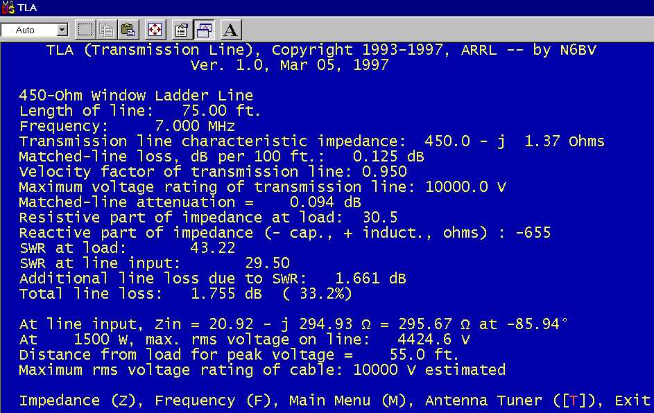
Using TLA we find the following feed line losses for a 75-foot feed line:
Note the following from the above:
- Line loss is now just under 2dB for TLA's estimate of a perfectly dry brand-new feed line (it's actually just over 2 dB if we use real measured losses on aged dry line rather than TLA's values). This does not include tuner losses, balun losses, or additional losses from less-than-perfect installation.
- Maximum RMS voltage on the transmission line is a staggering 4424 volts with 1500 watts. This is over 6250 volts peak voltage. (Even with 100 watts peak voltage would be 1600 volts!)
- Line input impedance is 21 -j295, this is what the tuner must match.
Suppose we add a well-designed "3KW" tuner to this system. Typical better tuners have the following component values and Q's:
- Capacitors: 4.5kV, 250 pF, Q=5000 at mid-setting
- Inductors: maximum inductance 38uH with Q=200
We will assume a perfect balun without any loss. (It makes very little difference by the way if the balun is on the tuner input. Don't think moving a current or choke balun to the input of a tuner is a solution. The balun is under the same common mode stress at ether end of the tuner.)
With 250pF maximum capacitance, matching the odd impedance of this short dipole requires a tuner with the above component limitations to operate with a Q of 30.4. The resulting loss is 233.6 watts or 15% of applied power, and maximum voltage across a capacitor is 4250 volts! You are almost at the voltage rating of 4.5kV, so any small imperfections will cause a capacitor to arc. The inductor in the tuner would also dissipate 192 watts, which would damage most inductors unless duty-cycle was very low.
Some tuners (like MFJ Tuners) would be worse than the above values, Dentron tuners would be close to the above values, and many tuners would not even be able to match the load impedances. Automatic tuners and pi-network tuners would have a difficult time matching an impedance like this.
A More Accurate Transmission Line Calculator
While the older version of TLA shown above is acceptable, newer versions are not. VK1OD has a much more accurate transmission line calculator at this link. It is a little tricky to enter data in the VK1OD calculator, so enter impedance exactly as I did below in the format used with 30.51-655 (no spaces):
|
|
With new dry heavy duty transmission line, we would lose about 2dB of our power in the feed line alone, and another 1.6 dB in a big well-designed manual tuner! This is 3.6 dB loss, more than half our power, and we have not included balun losses which could amount to another 1-3 dB loss with this load impedance. It is quite possible to have in excess of 6 dB loss on the lowest band using good heavy ladder line and a good tuner with an 88ft or 44ft dipole.
Conclusion
The lower limit in size of a multiband dipole before feed system and matching losses move to the edge of severe problems is about 200 feet on 160 meters, 100 feet on 80 meters, 50 feet on 40 meters, and so on.
A good rule of thumb is length in feet must equal 1.25 times the band in meters. The result is the minimum dipole length you can use without using a good matching system in, at, or near the antenna!
160 meters= minimum efficient length 160*1.25=200 feet
80 meters= minimum efficient length 80*1.25=100 feet
The G5RV length of feed line and antenna is the lower limit in size. A normal G5RV system, including tuner, typically has about 1dB of loss on 80 meters and less than 2dB system loss (including loss from coax and matching) on 80,40, and 20 meters. People seem to hate G5RV's, yet they now seem to be willing to further shorten the G5RV and recommend others do the same!
As an antenna is shortened from that length, losses in the feed system (even what Hams consider a good one) climb rapidly. 88 feet is just too short for an 80 meters antenna, because as you see above it is at the limit of what most tuners will match. It also places most tuners at their power limit at a few hundred watts of applied power.
The optimum length for a multiband dipole is near 1/2 wl on the LOWEST band, and the optimum open-wire feed line length is any odd multiple of 1/8th wavelength on the lowest band. This means an optimum 80-meter dipole would be about 125ft long, and the feed line would be 25-30ft, 75-90ft, or 125-150ft long. The longer the feeder, the more likely you are to having to trim it for optimum tuner performance.
Most tuners like to see impedances HIGHER than 50 ohms, and inductive loads at low impedances. Pi's and L's are NOT a solution to matching problems. They actually are significantly more restricted in matching range than a conventional T-network using the same general style and quality components!
feed line voltage is also a good way to estimate wet-weather performance of "window" ladder line. If voltages are more than 1000 volts RMS at 100 watts, operation in wet weather will certainly cause tuning or loss problems. Use TLA and other tools as a way to plan antennas. Remember, there are more important things than pattern! A good pattern is useless if we cannot efficiently feed power to the antenna.
©2004 W8JI
This
page has been viewed
times since creation
on July 25, 2004.
This entire web site
now averages over
1.5 million hits per
year, and the entire
web site now
averages about 500 different
visitors each
day.