Related Pages:
I became infatuated with Valiant when I first heard W8YAT on 160 meters in 1962. Bob was using a Valiant with a D-104. The big thump when that carrier came on and such audio!
I bought my first Valiant in 1970.
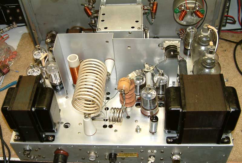
Chassis View
There are a lot of Internet modifications to the Valiant. My take on the mods is people are getting a little too carried away. The Valiant isn't all that bad. As time permits I'll add my mods here. All of my mods are verified with test gear, including spectrum and distortion analyzers.
HV Power Supply
Some people claim the power supply is weak. Factually, the supply is pretty well engineered unless you plan on tearing the Valiant all up and making it into a totally different transmitter.
I tested the supply on CW and AM. CW is easy. On CW, strings of dots at various speeds would show power supply defects. CW is also the worse case loading for the supply, since the dynamic power supply load varies quite abruptly and to extreme amounts as the tubes go into and out of conduction between dots and dashes. The unkeyed power supply load current is a few dozen mA, and the full load current is around 500mA.
AM is a little tricky to test, since there are both syllabic and tone variations. The supply has to be reasonably stable for slow dynamic variations and not have excessive ripple induced at audio frequencies by the peak load caused by peak modulator current. Let's look at just how good or bad a Valiant is.
CW Test
Running 475mA (ouch) and adjusting dot duty cycle and speed for maximum ripple, here is what my stock Valiant does:
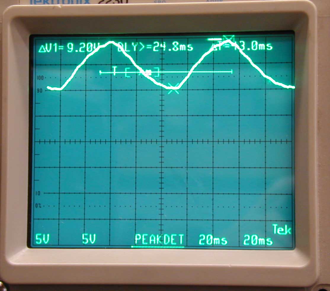
The scope is scaled for 100v/div, or 20x scale reading. 800 volts is the top line. The scope trace says ΔV1=9.20V on the top left. Multiply 9.2*20 = 184
The power supply has 184 volts p-p dc fluctuation with load. This fluctuation occurs because the power supply choke cannot recover fast enough to impede current when load suddenly stops, and likewise impedance cannot fall fast enough to hold voltage steady when load starts.
The mean supply voltage in my Valiant is 760 volts with no load. It is 620 volts under normal CW load. Most of that sag is because the filter choke is marginal on inductance for the bleeder current. This allows the supply to move higher than the .9*RMS of a perfect choke input supply.
We should not interpret a no-load supply voltage increase from lack of bleeder current or critical inductance as "weak supply". Well-designed unregulated single phase supplies typically sag 10-15% from no-load to full-load. The Valiant sag is less than 20%, and that could easily be improved to 12% or better with an increase in bleeder current or filter choke reactance.
As for the voltage bounce, almost any choke input supply behaves this way. Even a commercial BC transmitter will do this when the carrier is keyed at the right rate. This is not a sign of a weak supply. It is typical of choke input supply behavior under CW keying loads. If we CW key a 900-pound kilowatt AM BC transmitter with a choke input single phase power supply, it will behave the same way!
While I have not addressed this issue because it doesn't mean much to me or the signal, the first thing I'd try is resonating the choke with a non-polarized capacitor. It is often possible to find a "sweet value" of capacitor that takes much of the no-load voltage increase out. The capacitor-choke combination should be made resonant slightly above 120 Hz. There should be about 400 volts or so peak AC across the filter choke. From appearances and my experiences with other choke input supplies, I would say the addition of a single component (a capacitor across the choke) would pull no-load voltage down to 700 volts or less without changing full-load voltage.
A second option would be to load the supply heavier with a lower resistance bleeder resistor, but that would waste power and make extra heat. The no-load to full-load bounce would be greatly reduced.
Maybe someday I'll try tuning the Valiant supply choke to reduce the no-load voltage peak. For now, it does not appear to be that big of a deal. Remember the scope capture above shows the WORSE CASE dynamic load variation I could find.
We can see the effect of the power supply sag and overshoot on the CW envelope. Look at the hump in the leading edge of the CW envelope in the following picture:
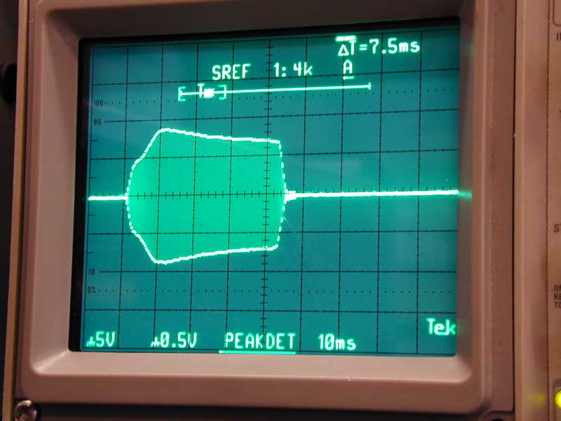
Notice the leading edge overshoot. The envelope overshoot at the leading edge is created by HV supply dynamics. Since the envelope is rounded and occupies 7.5 ms, it does not affect bandwidth. I opted to not do anything about it. (By the way, I reshaped the CW waveform from stock, more on that later.)
AM Dynamics
To test AM, I used a pulsed tone. I set the tone for maximum ripple and maximum dynamic variation. This wound up being about 300 Hz AF, and a pulse rate of 5 Hz. This test was running 350 mA and slamming the modulator current against the pin. you will never have it this bad in real life. Here is the worse case power supply error on AM:
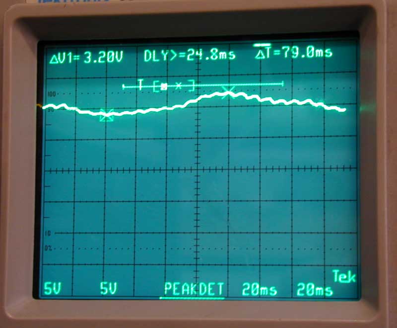
The 300 Hz audio ripple is down in the noise of power supply hum, and the total pulsed-audio dynamic voltage variation is only 64 volts p-p, or 10%. This pulsed variation is at a syllabic rate, and is only this bad under worse-case pulse audio conditions.
Supply voltage variation is not measurable as audio distortion on the output. Without any question, the Valiant does not need power supply work for AM operation. (By the way, this is with old original electrolytics!)
Modifications
Audio
Here is the 3kHz envelope of my Valiant after minor modification at 100% modulation:
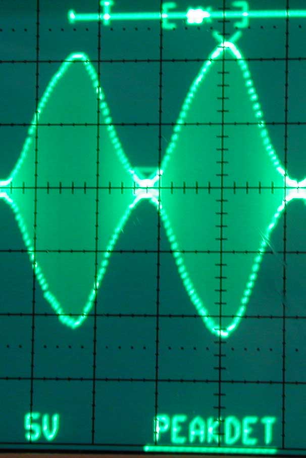
The photo below shows modulation at 350Hz. Notice the rolling off after the peak. The Valiant is running out of iron in the modulation transformer (the grids of the 6146's are fine) at low frequencies.
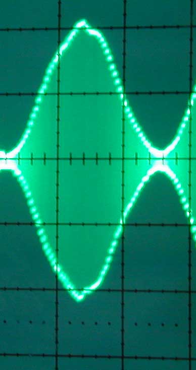
Comparing both envelopes, there is very little amplitude change. For a fixed generator input, my Valiant audio response is almost flat from about 300 Hz to 3500 Hz. The addition of a few capacitors flattened the audio response. I did not remove or change the value of power amplifier RF bypass capacitors. I did not remove the low-pass audio filter that follows the audio clipper.
As a matter of fact removing the audio lowpass filter is detrimental. Removing the low-pass caused the response to sag above 2500Hz! The audio filter, besides starting rolloff at 3500Hz or so, adds a slight upward modulation gain increase as an audio frequency of 3500 Hz is approached. This upward slope is just right to compensate downward slope caused by bypass capacitors. Take that filter out, and you'll also have to remove bypass caps. Removing the bypass caps is bad for RF, and allows harmonic and intermodulation distortion products generated in the modulator driver and output stages to modulate the PA for 10kHz and further away. No need to do that!
related pages: