Tuner Baluns on Input
|
Tuner Baluns on Input |
|
Sleeve baluns Balun and Transformer Core Selection 4:1 Balun Analysis Verticals and Baluns Common mode current Common-Mode Noise toroid balun winding Steel wool balun
10/2/2012 added data differential loss
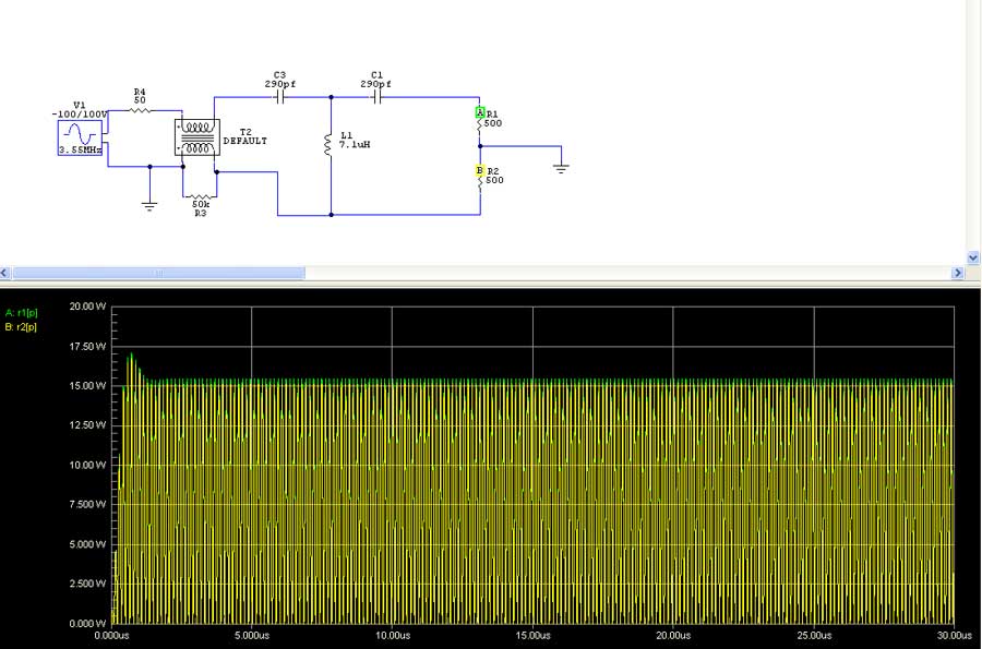
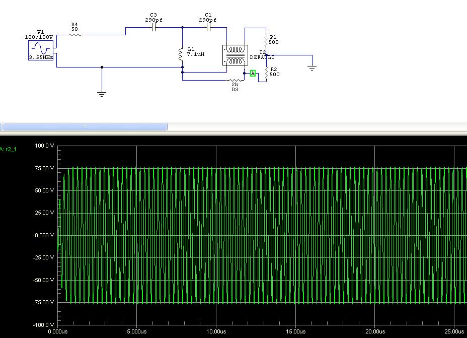
A common misconception is placing a balun on the input of a tuner causes the balun to work better. The thought or claim is the balun operates with a matched impedance, and that reduces balun losses. It also is thought or claimed moving the balun to the tuner input improves balance. Any article that claims placing a current balun at an unbalanced tuner input helps balance, or generally helps the balun work better, unfortunately is mistaken. Moving the current or choke balun to the input of an unbalanced network makes balance much worse on higher bands, and does not help lower bands. Let's take a close look at what actually happens when we move the balun to the tuner input. Spice ModelsIdeal Case Tuner with Balun on Input The following model has a near perfect balun on the input of a perfect unbalanced network. In the perfect case below ill-effects caused by floating the network, such as unbalanced coupling to ground from the network components, is ignored. Virtual components lack stay coupling to the chassis and cabinet. This is a much better tuner than any of us can build. The load is perfectly balanced with 1000 ohms total impedance. In this example, balun common-mode impedance is purely dissipative. 50K ohms would be a VERY good balun, with an impedance nearly impossible to obtain on any frequency. A practical balun would be much worse, but let's look at an extremely good case. In the circuit below, at point "A" (R1), power dissipation is indicated by the green trace. Point "B" or R2's power dissipation is represented by the yellow trace. All voltages and power levels are instantaneous peaks. The capacitors and inductors are assumed lossless. Applied "power" can be considered to be about 30 watts. Note: Resistor R3 represents represents the common mode impedance of the balun. The windings in T2 have unity mutual coupling, similar to a real bifilar balun. This is a simple but reasonably accurate way to represent the common mode losses of our ideal 1:1 current balun.
In the above case we see the load is very well balanced. The green and yellow peaks are nearly identical. The load receives well balanced power. Balun heating is 1% of R2's power.
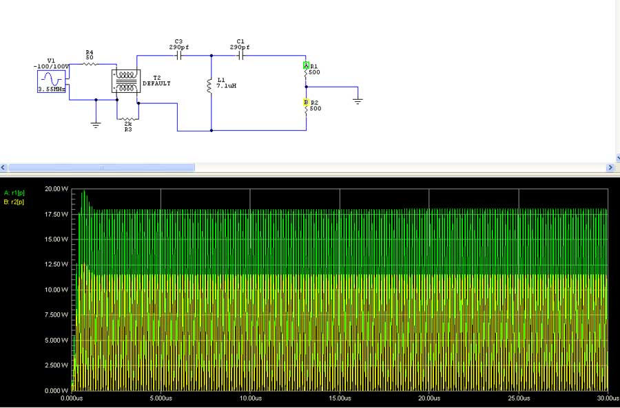
String of Beads Balun on Tuner Input Let's see what happens when a more typical "very long string of beads balun" is used. In this case we will ignore balun flaws and assume ideal resistance, with zero stray or shunt capacitance:
In this case power in the upper side of the balanced load, represented by R1, increases. There is also a shortfall of power in the lower side of the load. Power input slightly increases (I didn't readjust the network for the changed impedance) to 32.5 watts R1 = 18 watts R2 = 11.5 watts We have 6.5 watts of load unbalance. The balun dissipates about 3 watts.
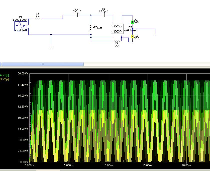
Balun on Tuner Output Now let's compare the system above with a system having the same string-of-beads balun on the tuner output:
Notice all power levels are unchanged!
We lost absolutely nothing by moving the balun to the output!
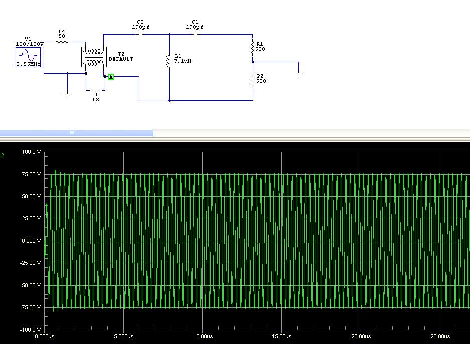
With the balun on the input we have the following peak common mode voltage:
We have about 75 volts peak across the 2K ohms of balun common-mode impedance, or about 3 watts dissipation. This is about 10% of applied power. With 1500 watts the balun would be dissipating 150 watts. The beads would be too hot to touch in a matter of seconds.
Now let's examine heating caused by common mode voltage with the balun on the output.
Notice we have exactly the same balun heating power. Nothing changed. The balun core is under exactly the same electrical stress. Nothing was gained by relocating the balun to the input. Nothing was lost by moving it to the output! The same core size is required, balance is the same, and heating is the same. In the real world, we would find balance WORSE with the balun on the tuner input. This is because a typical group of medium sized matching components would have about 50 PF or more capacitance to the chassis on forty meters, with a very large portion of capacitance on the stator side of the tuning capacitor and the "ground" side of any inductor. In every tuner I have tested with an unbalanced network and a balun on the input, balance has been very poor on higher frequencies.
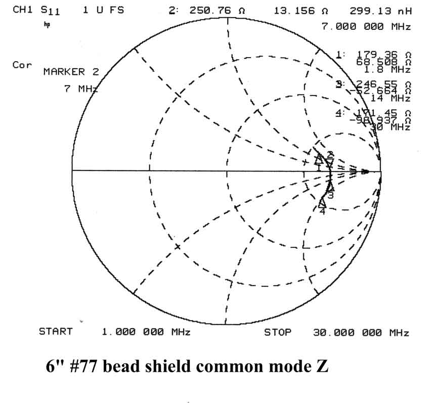
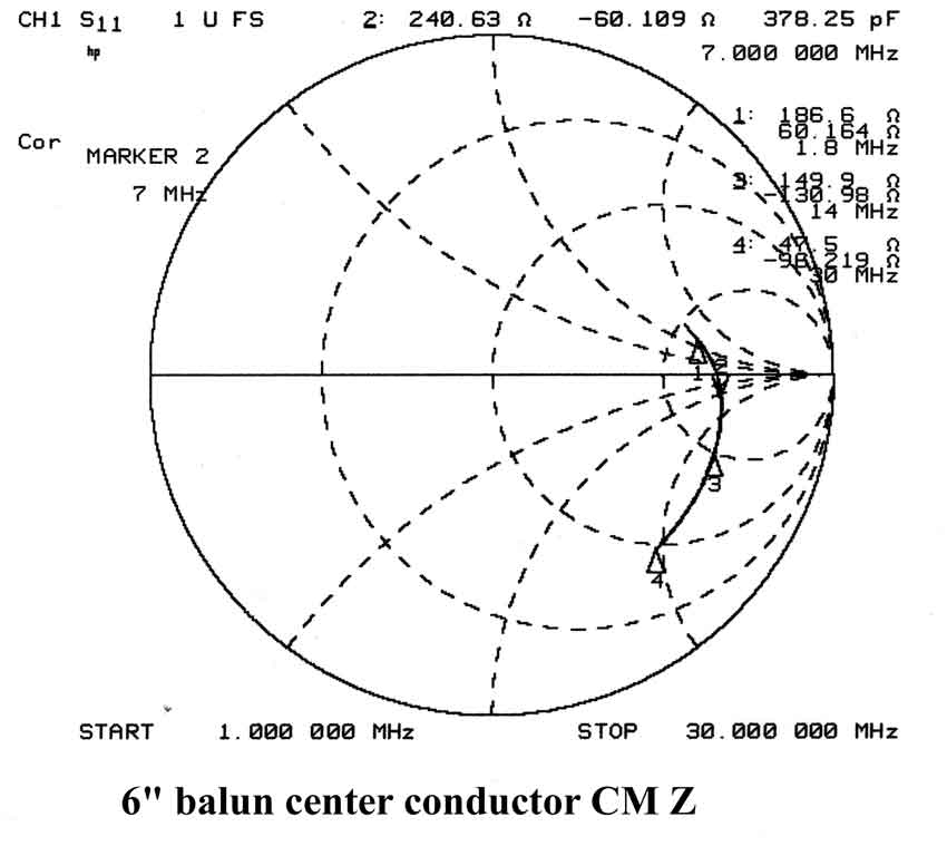
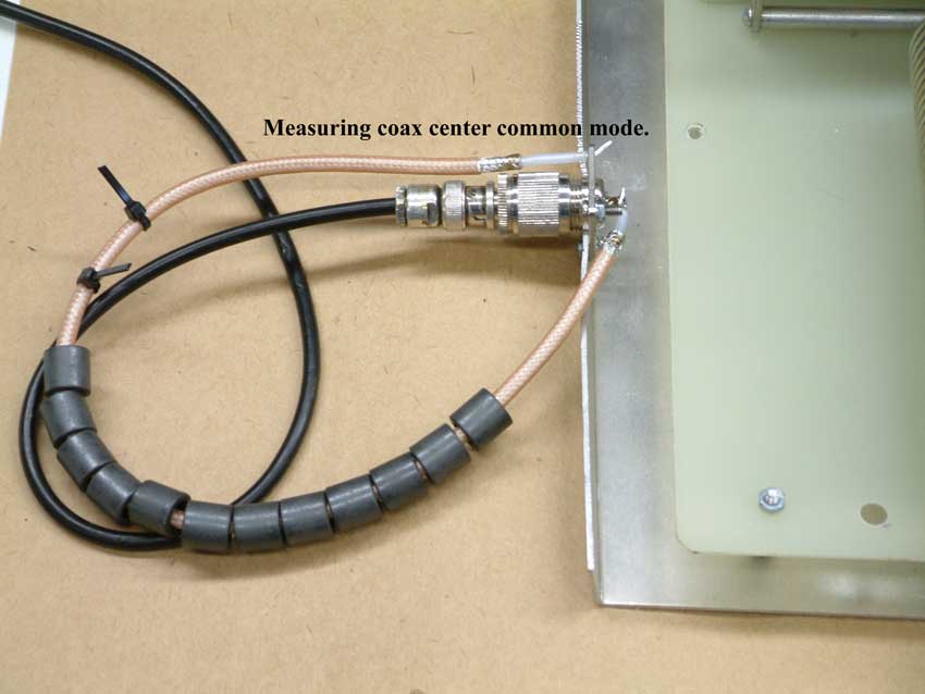
Real Component TestLet's look at real components and see how they work. First let's measure the common mode impedance of the bead balun I'm going to use:
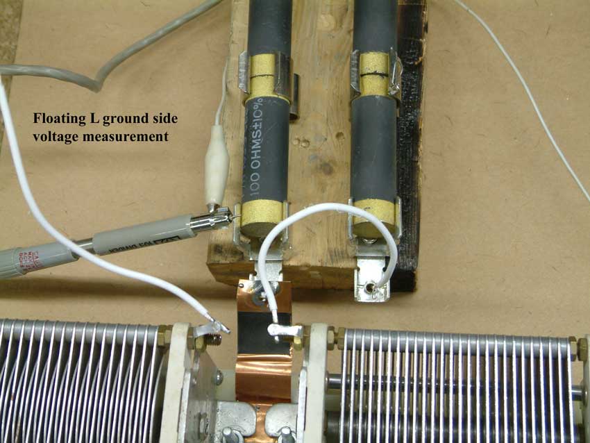
This is the tuner configuration. In this case it was setup for a floating-L network with balun on the input:
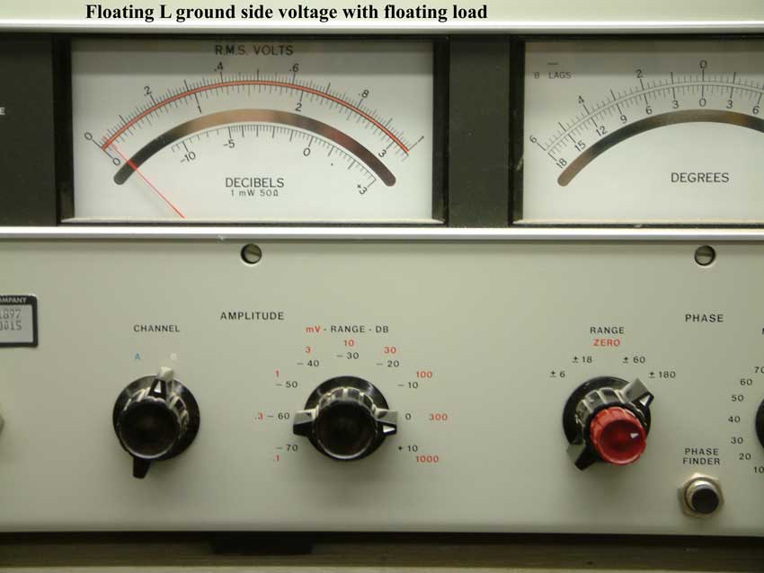
The ground side of the floating L measured 10mV at the load:
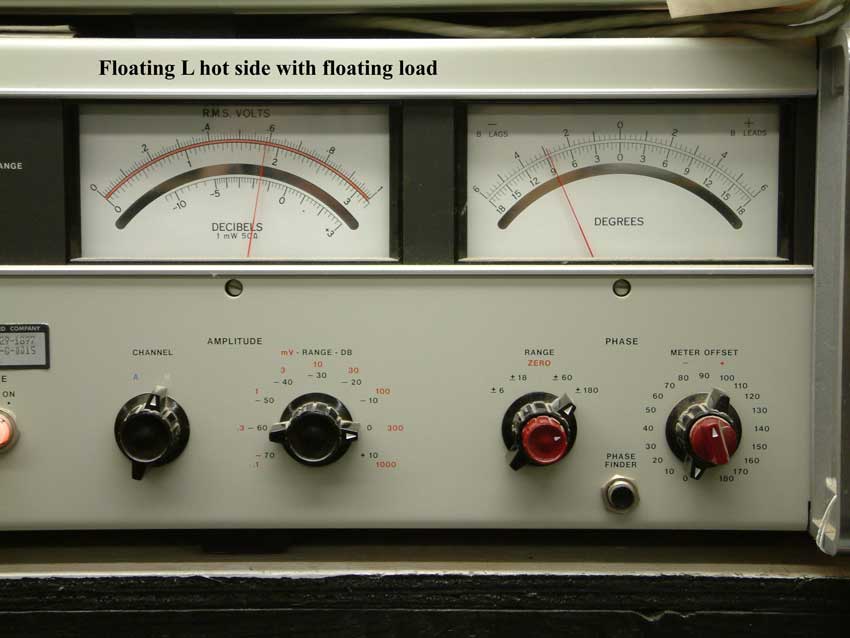
The "hot side" of the floating L measured 185mV: This is worse than the model because the beads do not have the 2000 ohms impedance the model assumed. The beads only have a few hundred ohms impedance. The model also does not include significant network-to-chassis stray impedances that are present, which unbalance the output terminals. The large amount of unbalanced coupling from network components to chassis is commonly overlooked. Components are not physically or electrically identical when viewed from each balanced load terminal to "ground". Impedance to ground is not nearly as high as we might expect, and impedance to ground varies greatly with actual component settings and operating frequency. More Accurate Model RepresentationIn a real device with real components, stray impedances distributed through the system create significant problems. For example, above 40 meters there is significant change in balun impedance from the addition of ceramic-insulated feedthrough terminals, wire connections, metal cases, and even dielectrics. We might eliminate the metal case to reduce capacitance, but without a metal enclosure everything around the balun affects common mode isolation and balance. Many devices test very well on a bench, but do not hold the expected performance in the real environment. Based on my considerable experience, which includes thousands of hours evaluating baluns and tuners, it is foolish to go overboard with impedance. Also, some of the poorest systems appear to offer the best performance. A balun operating at high power and remaining perfectly cold often indicates a balun inadequate for the job. The circuit below, while still incomplete, more closely represents a real tuner.
CS1 through LS1 are shunt impedances. They are capacitive at root, but combine with series inductive reactances and losses. Overall, they will always be partly resistive, and may be capacitive through inductive in actual net effect on the system. Making matters worse, values of everything significantly change with operating frequency, setting of L1, and capacitor C1 and C2 settings. L1 is a single inductor. Since parasitic inductive and capacitive reactances are in series, the net reactance is reduced and can sometimes reach very low values!
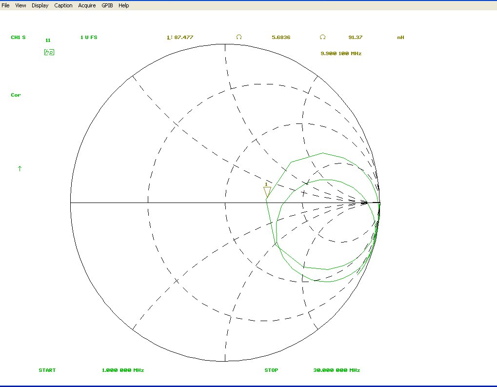
Looking at L1, we find various areas of L1 are in series to balanced output terminals B1 and B2. The reactance of these areas varies as L1 is adjusted. The effect of this is the stray path through LS1 to the tuner enclosure varies in series L, C, and R as the roller is adjusted. If we watch terminals B1 or B2 to ground, looking at common mode impedance, we find both the ratio and absolute impedances vary. Lower inductance settings push the lowest impedance frequency of B2 lower, because L1b and c get larger. L1a is always in series with B1, so the circuit is asymmetrical as viewed from antenna terminals B1 and B2. Further complicating matters and aggravating symmetry problems, C1 and C2 have varying CS1 and CS2 as the capacitors are rotated. Since the stray of CS1 and CS2 to chassis is normally capacitive across HF into VHF, it parallel or series tunes L1's sections in varying amounts. The direction and amount varies with frequency, and is never symmetrical at B1 and B2. When viewed on a Smith Chart, terminals B1 and B2 are typically a series of circles spiraling from reasonable values of expected shunt capacitance on 160 meters, circling through inductive and capacitive swings, down to a fairly low and unequal shunt impedance on 30 MHz. Casual designers look at the tuner and assume B1 and B2 (balanced terminals) represent some impedance equal or higher than BALz, but that is never the case unless through chance the equivalent effect of all strays parallel tunes BALz to a high parallel resonant impedance. There probably isn't a worse system for consistency and reliability in common mode suppression as obtained when a balun is moved to the input of an unbalanced network, especially with physically large components.
The Roller AloneShunt capacitance to ground is problematic with baluns, and large components in networks are much worse. This problem is aggravated by series inductive reactance in the network. For example, here is the roller inductor frame-to-chassis impedance of a relatively small roller inductor. This roller has adequate inductance to cover 160-meters, and is spaced 2 inches above a large flat copper sheet. The roller is set near a typical position for 40 meter operation:
At 10 MHz and 25 MHz, roller frame to chassis impedance goes through a minimum. Inductor terminal impedance, and terminal impedance variations with frequency, are not symmetrical on the "cold" (roller wheel and frame terminal) and "hot" (capacitor junction terminal) side of the inductor. Resonant points and terminal impedances to the chassis vary greatly with roller wheel position, making it impossible to balance matching network terminal impedance to chassis. A balun on the input of a floating unbalanced network is a waste of time. The system models this way, and the system also measures this way. It is just a very bad idea for system balance. The Balun (Common Mode Choke) Loss Argument
Some have proposed balun conductor heating due to SWR on the balun's transmission line is a major concern. Several important things are missed in the linked analysis. The idea differential-mode (transmission line mode) heat is the dominant problem is, at best, incomplete. Most people with real-world balun experience would disagree with claims differential mode heating is a dominant design issue. Unless operated at very low load impedances, the dominant heat mechanism in any normal current balun is from common-mode (choking) core excitation. Differential mode, or transmission line mode heating problems pale in comparison to common mode heating problems. The example linked uses a terrible balun design for many reasons. Let's look at the 50-ohm transmission line used in the above linked analysis. When we place a balun or common mode choke directly at a matching network's input or output terminals, the balun or choke's differential mode impedance (transmission line impedance used inside the balun) does not need to match the system. Provided we do not transform to difficult impedances at higher frequencies where the transmission line might be of electrically significant length, standing waves in the balun can be compensated though simple matching network readjustment. As a matter of fact, 50 ohms is a very poor choice of balun transmission line impedance for this application. We ideally want differential impedance (transmission line impedance) of a tuner output balun to be the geometric mean of the highest and lowest expected impedances seen on the highest bands. Designing at the geometric mean results in minimal differential mode impedance mismatches and minimizes unwanted impedance transformations. Let's assume a practical matching network has a useful ten meter impedance range of 15-2000 ohms. Further, let's assume antenna systems fall with equal likelihood anywhere in a 15-2000 ohm range. In this case, the designer should choose the geometric mean of the highest and lowest impedance. This would be (sqrt of 15*2000) a ~173 ohm balun differential mode (transmission line) impedance. A well-planned design would use the smallest physical size twisted pair that safely handles maximum expected differential mode average current and highest instantaneous peak voltage. At 15-2000 ohm impedance range at 1500 watts, current limits would dictate conductors sized to carry over 10-amperes intermittent current without overheating failure, and 2450 peak volts of dielectric strength. Since dielectric failures are generally instantaneous, it is important to include extra margin. Because of transmission line effects, peak voltage can exceed maximum rated network component voltages, so we want to allow for a certain maximum load impedance and peak power plus headroom. Voltage requirements are easy to meet, most E or EE Teflon wire withstands several thousand volts. Once we determine impedance, we should consider standing waves inside the balun transmission line on higher bands. With ten feet of 150 ohm twisted pair, and with an SWR as high as 13.4 : 1 (2000/150) at the high voltage end, we could have 11.25 ohms at the network. This would be 11.55 amperes RMS current. This would call for a fairly heavy wire. Using EE Teflon insulated stranded wire, #16 gauge would handle 1500 watts in normal ICAS service. Note this also keeps impedance inside the network's range. With proper balun design, standing wave ratios inside the balun are reasonable. SWR will not come close to 60:1. By far, the largest balun heating effect would be from core excitation due to common mode current flowing through the balun windings (I^2*R core heat), or if we prefer, heat from voltage impressed across the windings from end-to-end (E^2/R core heat). With a typically obtainable internal 2500 ohm j0 CM impedance at optimum frequency in a very good balun or CM choke, core heat from 1500 watts into a 2000 ohm balanced load would be about 300 watts. This does not get any better if the balun is relocated to the network input. Looking more than superficially, the "lower loss justification" quickly goes away. We have not considered balance. If we want the tuner's output terminals to be balanced as closely as practical (it is almost impossible to closely balance a high impedance line at upper HF), we would quickly discard any notion of placing a balun at the network input. When does moving the balun help?Moving the balun helps performance only under very specific conditions. 1.) When the network is a double-balanced FLOATING network that is perfectly symmetricalIn this case, it works because we almost don't need the balun. Absent any common mode current fed back from the antenna, the move will reduce excitation of the balun core almost completely. In this case, the balun actually has very little use at all! It can be eliminated in most cases with very little effect on system balance. With the balun on the input of a balanced tuner, the tuner becomes a balanced voltage source. 2.) When the network is a double-balanced network that is perfectly symmetrical and grounded in the centerIn this case a modest balun is required, but the tuner becomes a very "stiff" split voltage source. It's actually just as difficult to build the best kind of tuner, a tuner that provides a balanced current source with high common mode isolation, by using a double network. If we spent only a fraction of the additional component expense required to build a "balanced tuner" and used the money to build a good current balun, we could have a better-balanced tuner in much smaller space! Instead of working towards a good current balun, some designers have thrown money into a system that creates more new problems then it cures old problems. Balanced tuners are great when the load is closely balanced. They are not so good feeding Windom, Zepp, or other antennas operating in the nether world between perfectly balanced and perfectly unbalanced. They also generally, for the same dollar investment, will not outperform a conventional unbalanced network with a properly designed balun on the output. You can see actual load balance measurements, including phase, on this page. Ironically, moving the balun to the input only works when the balun is not needed!
|